News:

Forum may be experiencing issues.

Main Menu
Menu

Show posts

This section allows you to view all posts made by this member. Note that you can only see posts made in areas you currently have access to.

Show posts Menu

Messages - solderfumes

#1
I've been known to perform surgery on 16mm Alpha potentiometers -- taking them apart and modifying them to make no-load tone pots for guitars, changing the resistive elements to make push-pull pots with unusual values, etc -- and I'm wondering if it's possible to do the same to the 9mm Alpha potentiometers, as I've never actually seen one in person before:

https://www.taydaelectronics.com/1m-ohm-logarithmic-taper-potentiometer-round-shaft-pcb-9mm.html

In particular, right now what I'd like to do is to pop it open and cut the resistive element to make a no-load tone pot.

I know that some (or maybe a lot) of you use these extensively in 1590A builds; have any of you ever tried this?
#2
I've bought NOS J201 and 2n5457s from my local electronics shop -- of questionable quality, mind you -- but moving forward I intend to use still-produced SMT components with the little adaptor boards.  I wish I'd done this already, as I'm working on a compressor that relies on 2n5457s and it appears mine might be fakes.
#3
General Questions / Re: Input Capacitor Theory
May 10, 2017, 11:10:57 PM
I think you hit the nail on the head.  I imagine reactance plays into it only insofar as the capacitor forms a voltage divider with the input impedance of the next stage.
#4
General Questions / Re: Sunking (2010 version)
May 03, 2017, 06:21:17 PM
You're talking about the one in "Sunking_Etchable.pdf" in the .zip file linked here, right?

http://www.madbeanpedals.com/projects/ARCHIVE/OD_Dist_Boost/Sunking.zip

Haven't used either etchable layout, but the schematic looks about the same as the newest one that's currently linked on the Etcher's Paradise page, at least (save for the new features).
#5
Open Discussion / Re: Amp Emulators
August 09, 2016, 06:40:55 PM
Are you averse to smartphone/tablet apps?  I quite like Amplitube on my iPhone, and use an iRig Pro to connect my guitar.
#6
Quote from: samhay on June 21, 2016, 10:41:58 AM
>the pickup was actually wired wrong internally: the coils were wired out of phase!

This is one way to wind a humbucker and may have been intentional.

That did occur to me, that maybe wiring it out of phase by default would make it seem less overwhelming to the uninitiated, and the volume would balance better with other pickups.  But some other forum posts on TalkBass indicated that this is probably just a manufacturing defect.

Quote from: GermanCdn on June 21, 2016, 03:30:03 PM
Needs more switches.

Time to install a preamp and onboard compressor....

I did a little more fiddling last night and found that putting the middle pickup in series with the neck-side coil of the ThunderBlade gives a real good satisfying tone, which I would use as a substitute for a split-coil P in a pinch.
#7
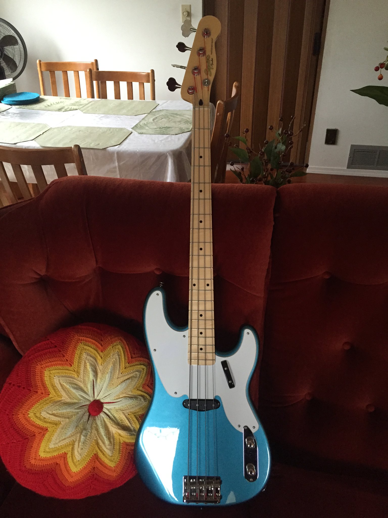
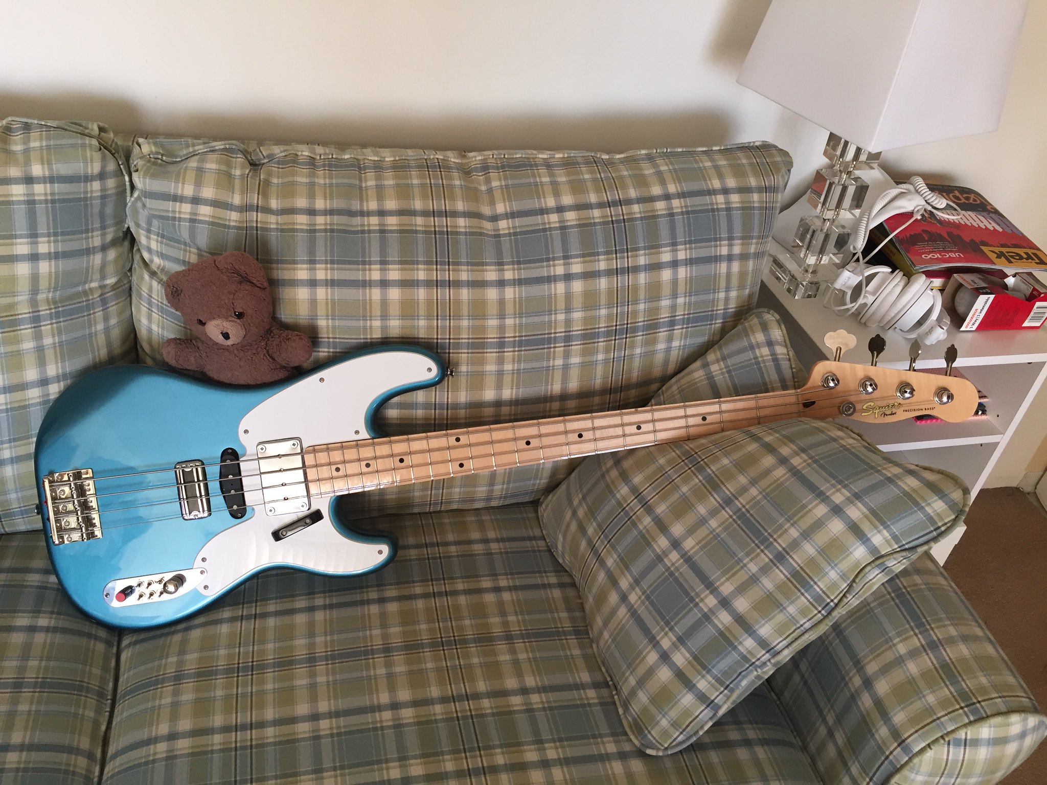
New bass day!  Well, "day" being used loosely, as the entire process has taken half a year.  I spotted this beauty on Boxing Day for $99:

IMG_2565 by dickolaswang, on Flickr

Single-coil Precision basses have never really been my thing, even though they look so cool, but I love the Squier Classic Vibe stuff so even with a few dings and dents $99 is an absolute no-brainer, if only just to flip on Craigslist.  I didn't buy it to flip, though, I bought it because I've had a two-year-long obsession with this bass:


So, I immediately started looking for a TV Jones ThunderBlade pickup.  Getting one was a slow process, because there weren't any TV Jones dealers in Vancouver.  One local shop was going to become one, but they had a lot of trouble properly closing the deal with TV Jones.  In the end it took three months to get the pickup.

I thought I'd also try and add a mudbucker in the neck position like the 70s Telecaster Basses because I've always liked that big deep sound, especially when playing with a pick.  I opted for an Artec mudbucker instead of a Fender Wide-Range humbucker, because when you think mudbucker, you think Gibson, not Fender.  They're dirt cheap on eBay -- I think this one goes for under $50USD (which unfortunately translated to something like $80CDN -- the Canadian dollar sucks right now).  There are two varieties, one with ceramic magnets and one with alnico magnets.  I opted for the alnico version, because I thought the ceramic one might be overwhelming.

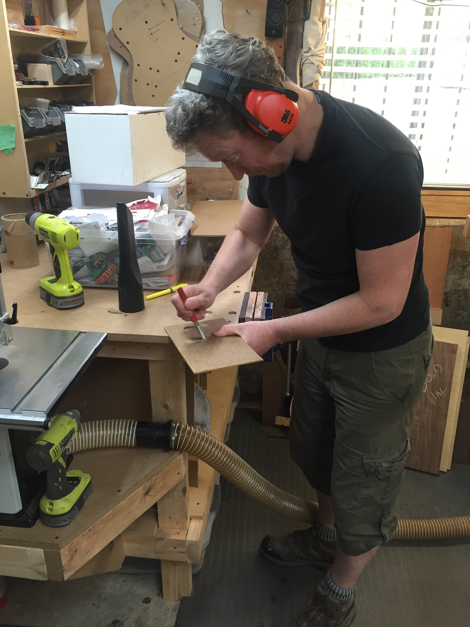
Once I finally got both pickups, I needed some woodwork done, so I called on my friend Ed Bond, of Halcyon Guitars (http://www.halcyonguitars.com/).  He's a busy guy, but eventually he was able to squeeze me into his schedule.

IMG_2733 by dickolaswang, on Flickr

Ed was the production manager of the Vancouver Larrivee factory for something like 14 years, and he makes stripped-down but amazing sounding acoustics under the Halcyon brand.  I have two of his acoustics.  He's a great guy to work with and makes an awesome product.  Unshown here: Ed filled a big distracting dent on the neck with some Crazy Glue so it's no longer a distraction while you're playing.

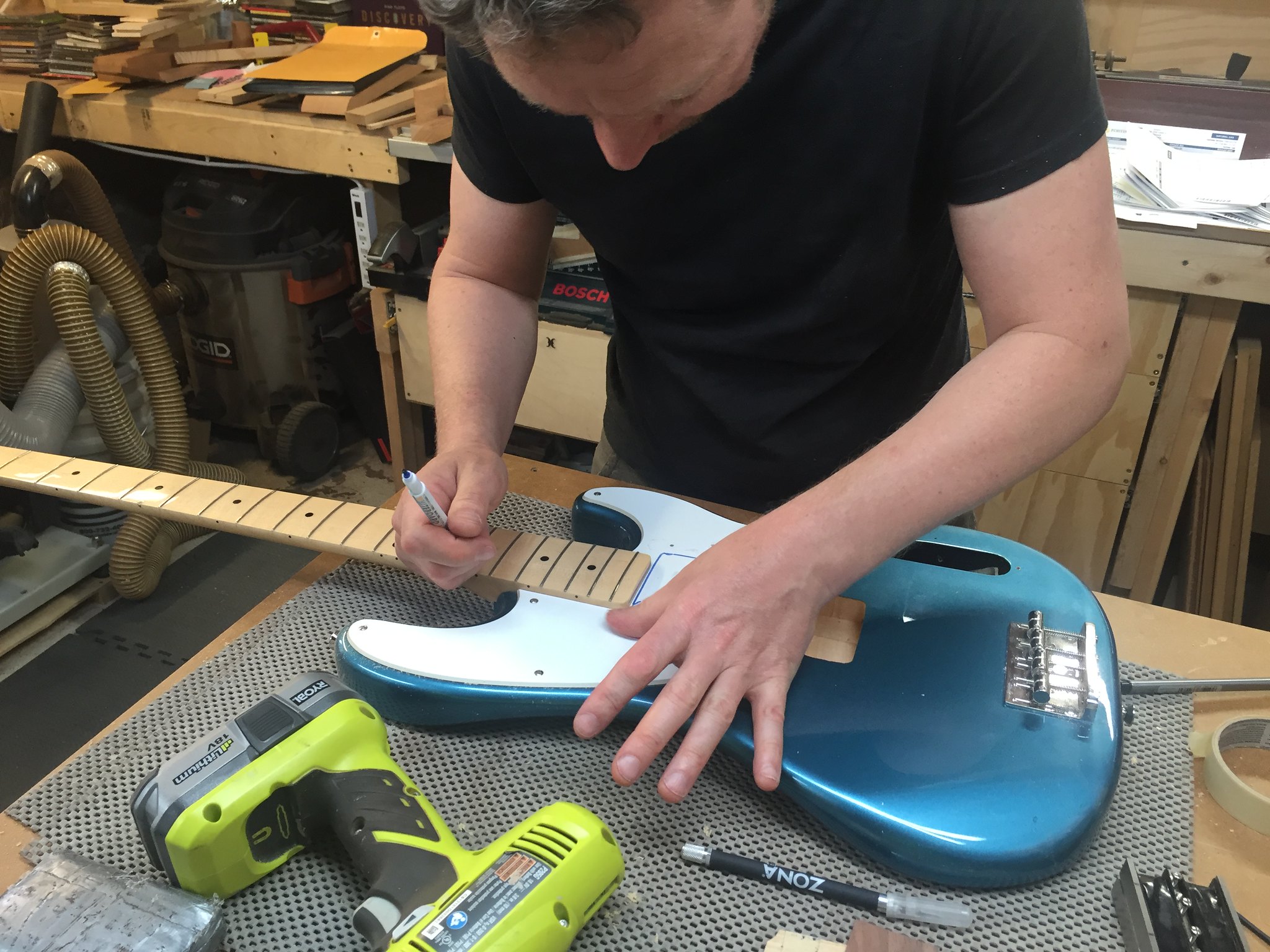
IMG_2734 by dickolaswang, on Flickr

There's one of his Halcyon headstock faceplates, here being used as a thickness gauge.

IMG_2735 by dickolaswang, on Flickr

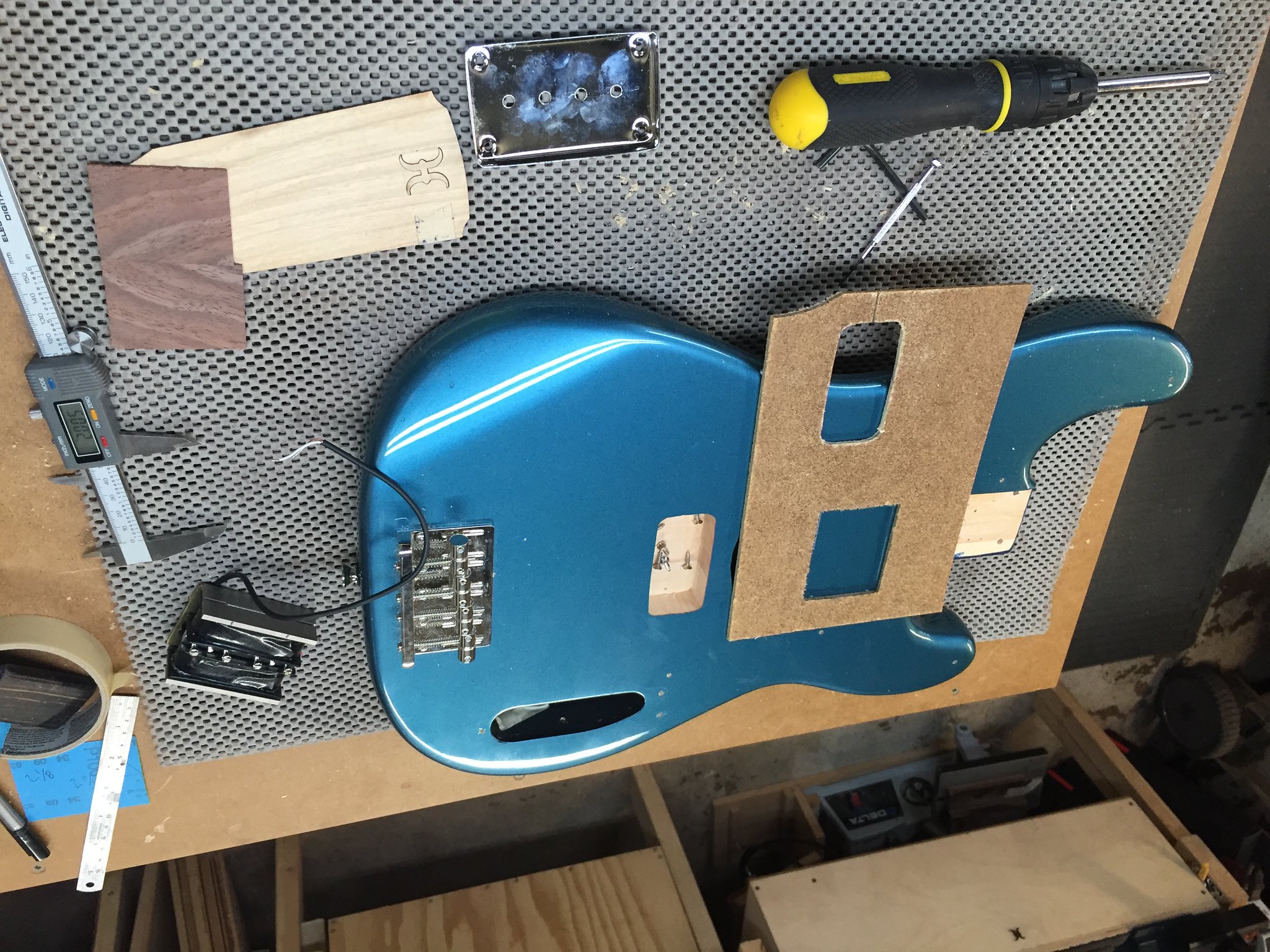
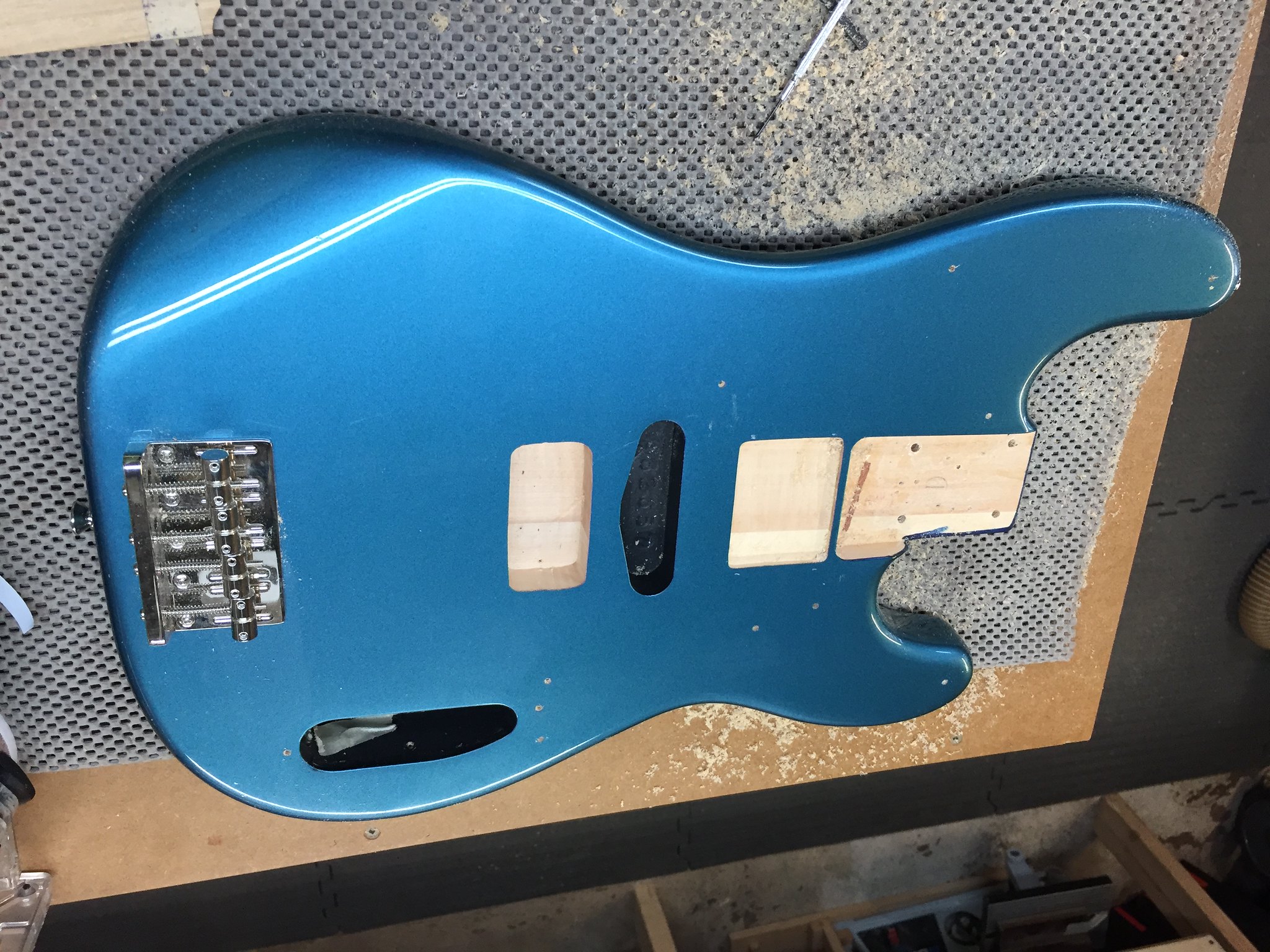
Mudbucker mounting is weird: the pickup itself doesn't screw into the body, it just sits in the cavity, held in place by the cover.  Height adjustment is generally done with shims.  The cover is quite tall, so we had to mount the cover flush to the body to keep it from interfering with the strings.

IMG_2736 by dickolaswang, on Flickr

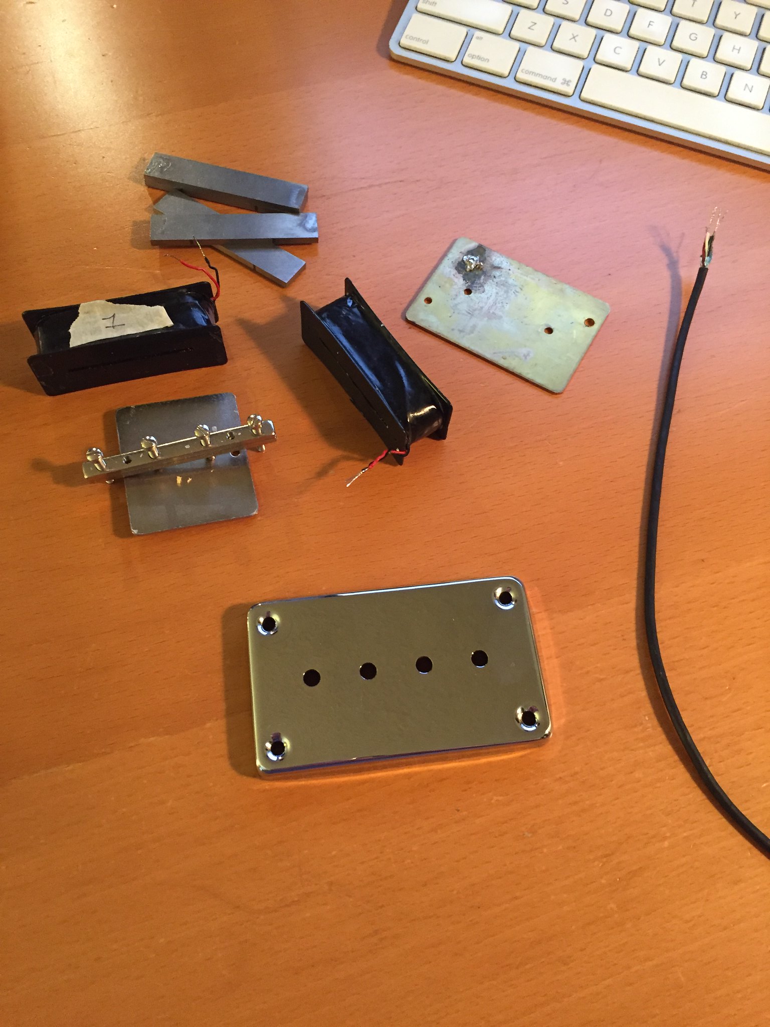
With the body all done, it was time for the wiring.  I wanted to be able to coil tap the mudbucker and/or wire it in parallel, but it comes stock with one-conductor cable, so I disassembled it and modded it with four-conductor cable.  Good thing I did, too, because the pickup was actually wired wrong internally: the coils were wired out of phase!  You get what you pay for, I guess.

IMG_2747 by dickolaswang, on Flickr

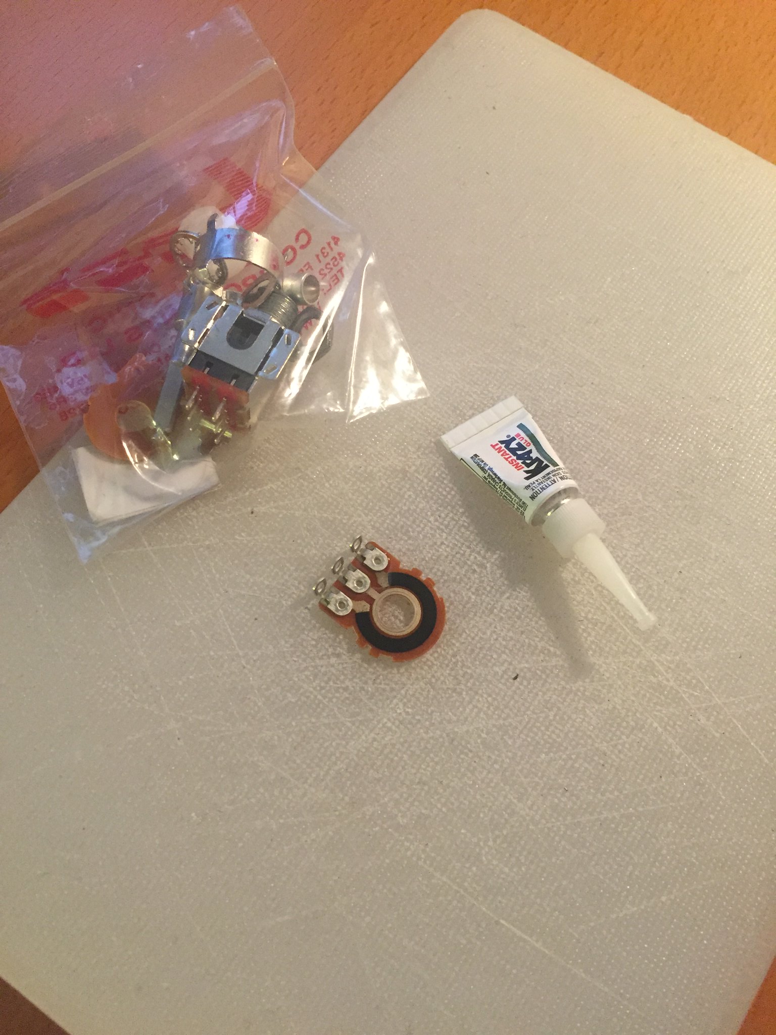
Next, a no-load tone pot.  I do this with a dab of Krazy Glue on the copper part of the outside track connected to pin 3 of the pot.

IMG_2748 by dickolaswang, on Flickr

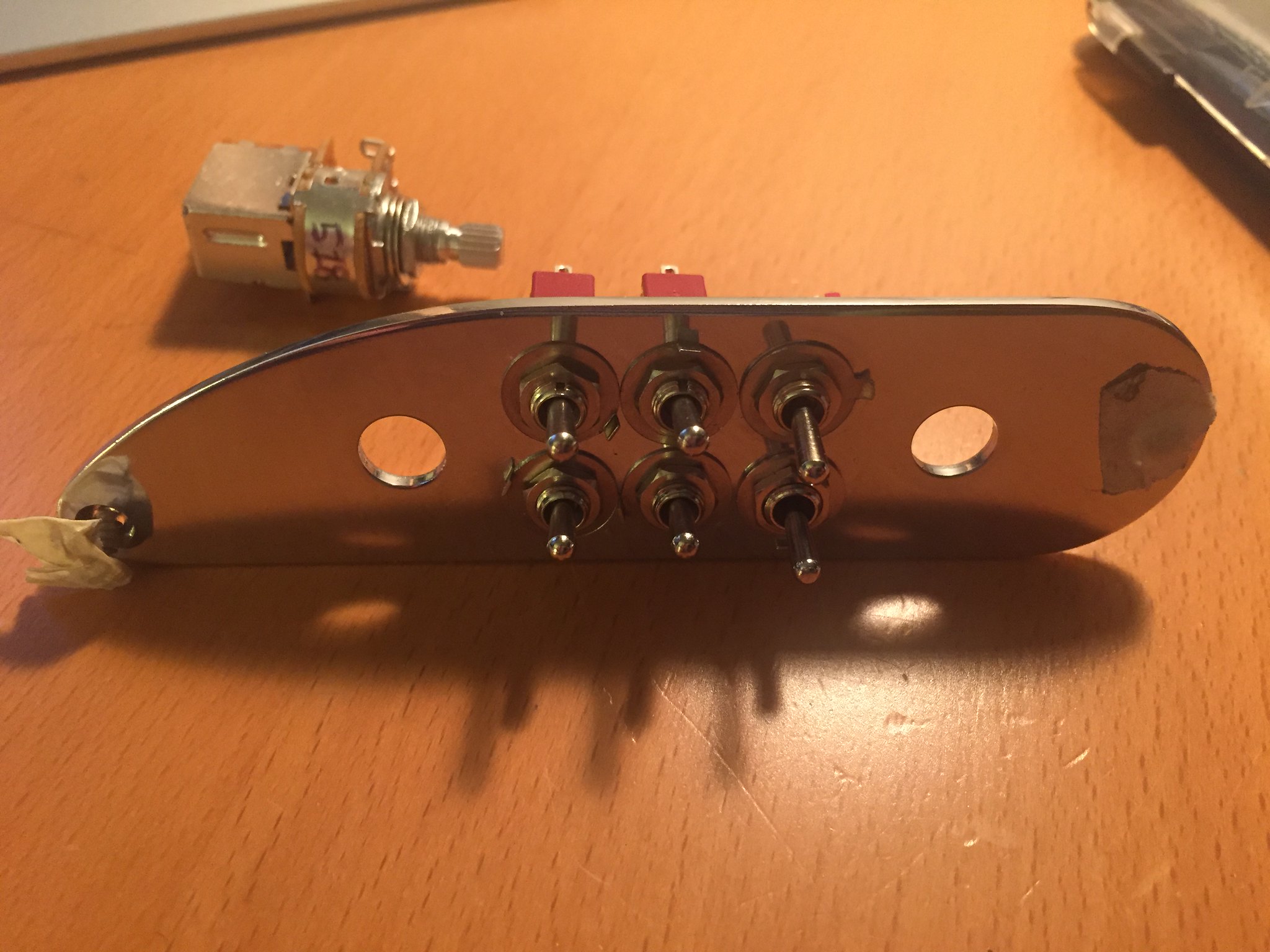
To implement the coil splitting and parallel wiring, I used the volume push-pull switch and one SPDT toggle to implement Seymour Duncan Triple-Shot-type switching on the mudbucker.  This way you can get the regular series wiring, or parallel wiring, or each coil on its own.  I did the same using the tone push-pull switch and another SPDT toggle for the ThunderBlade.

Even though I envision this bass more as three single-pickup basses than as a three-pickup bass, one way or another I needed a pickup selector.  I figured it'd be easier to drill three holes for toggle switches than to cut a straight opening to suit a Strat-style 5-way switch.  Given that it was going to take three toggle switches anyway, I opted for Dan Armstrong Super-Strat wiring, which uses two DPDTs and an on-on-on DPDT to give twelve combinations of the three pickups, including several settings with the pickups combined in series.  I'm hoping to find some series combination of the original single-coil pickup and one of the coils in the TV Jones pickup that will sound like a regular split-coil Precision.

The last toggle switch bypasses the volume pot.  It isn't a straight blow switch: it lifts pin 1 of the volume pot from ground, so that when the volume is turned all the way up, it doesn't load the signal at all.  It's just a little easier to wire.  I like to have the volume bypass and no-load tone pot for recording: in my mind, you're getting the purest possible signal recorded, allowing better tweakability after the fact.

IMG_2749 by dickolaswang, on Flickr

And at last, the finished product, in the hands of my favourite bass player:

IMG_2780 by dickolaswang, on Flickr

Well, almost finished.  I want to replace the tone knob with a better-looking one, as the stock ones are meant for knurled-shaft pots and my tone pot has a solid shaft.  More frustratingly, the TV Jones pickup that I waited two months for is actually defective.  It came with four-conductor wiring, but somehow two of the connections are shorted internally somehow.  This means my switching doesn't work quite yet, so I'm still waiting to see if I can find any useful settings that combine one of the coils with the middle pickup.  The normal series mode works fine, at least, and it gives me the tone I was looking for: lean and powerful but not muddy.

The mudbucker is wild!  I've never used anything like it before.  It's almost overwhelmingly hot and, well, muddy.  I think maybe I should have gone with the ceramics to brighten up the tone a little bit.  It definitely delivers on its promises, though, and sounds great picked.  The coil splitting and parallel wiring were a good call.  It's much less dark and produces a lot more growl in these settings, especially in parallel mode.  It doesn't play that well with the other pickups, because it's so hot (wound to 30k!) that when it's combined in parallel with either of the other pickups, it gets almost totally dominated by them.  Also, I can't imagine you'd ever want to put it in series with anything else, as it's so loud and so dark already that you'd just be getting pure sludge.  What might have been a better use of resources would be to use a stereo output jack and wire the mudbucker up to its own output, for use as a "subwoofer".

I'm really excited that after a long wait I finally have the bass I've been fantasizing about for two years, done my way.  Feels good!
#8
Build Reports / Re: Zendrive/Battery/1590A
May 24, 2016, 09:37:08 PM
Dang.  Ever try your hand at a ship in a bottle? :)
#9
It's all about Ohm's law applied to voltage dividers, and thinking of the capacitor in terms of its frequency-dependent impedance.  The cap doesn't so much "stop" frequencies as provide different impedances for different frequencies, and it's when this impedance forms part of a voltage divider with the resistor that you get rolloff of different frequencies.
#10
I'm from Vancouver and have never been to Montreal, but I think the general idea is that Montreal has culture and Vancouver has nature.  In my experience, people mostly come to Vancouver for hiking, skiing, boating, etc.

On the culture side, it should be noted that Vancouver has really exceptional Asian food.  Loads of craft breweries starting up around here too.
#11
How Do I? Beginner's Paradise. / Re: 1PDT...?
May 12, 2016, 04:36:47 AM
Quote from: jimilee on May 11, 2016, 12:43:52 AM
I blame the metric system.

Obligatory:

#12
Quote from: BrianS on May 02, 2016, 01:48:23 PM
Brian I know you're real busy and if you can't answer this perhaps someone else can. You built the Civil War version and the only difference  that I can see between it and the Green Russian (used this because its on the same page) is the 430p caps.  So C2, 5 and 8 are basically determining the gain level between the two versions?  And the Triangle and Creamy Dreamer would have the most gain since they are 560p (I know there are different parts used/omitted on these also).  I am just trying to understand the process here.

R23 also differs.  It's 2k7 on the Civil War and 2k on the Green Russian.  That resistor affects the gain on the final transistor stage.
#13
Quote from: m-Kresol on May 02, 2016, 03:13:59 PM
Thanks guys

Quote from: daleykd on May 02, 2016, 12:10:04 PM
Also, I think you need to jump pins 1 and 8 on a MAX1044/7660S.
Those are the "S" versions (actually S stands for super), where you have the "boost" pad for more output current.

EDIT: Here's an excerpt from the data sheet:

Quote
By connecting the Boost Pin (Pin 1) to V+, the oscillator charge and discharge current is increased and, hence, the oscillator frequency is increased by approximately 3.5 times. The result is a decrease in the output impedance and ripple.

I think typically the reason you use the boost on those chips is to get the oscillator frequency out of the audible range.  If you don't, it's very likely that you'll get oscillator whine in your signal path.
#14
Yes definitely solder them in.  If it doesn't fit, it might be that the board was designed for switches with PCB terminals instead of solder lugs?
#15
Oops, right, I meant "work" in the sense of "act as a mild distortion/boost", sorry.