News:

Forum may be experiencing issues.

Main Menu
Menu

Show posts

This section allows you to view all posts made by this member. Note that you can only see posts made in areas you currently have access to.

Show posts Menu

Messages - BRGPollen

#1
          I will snap some as soon as I get home!
"B"

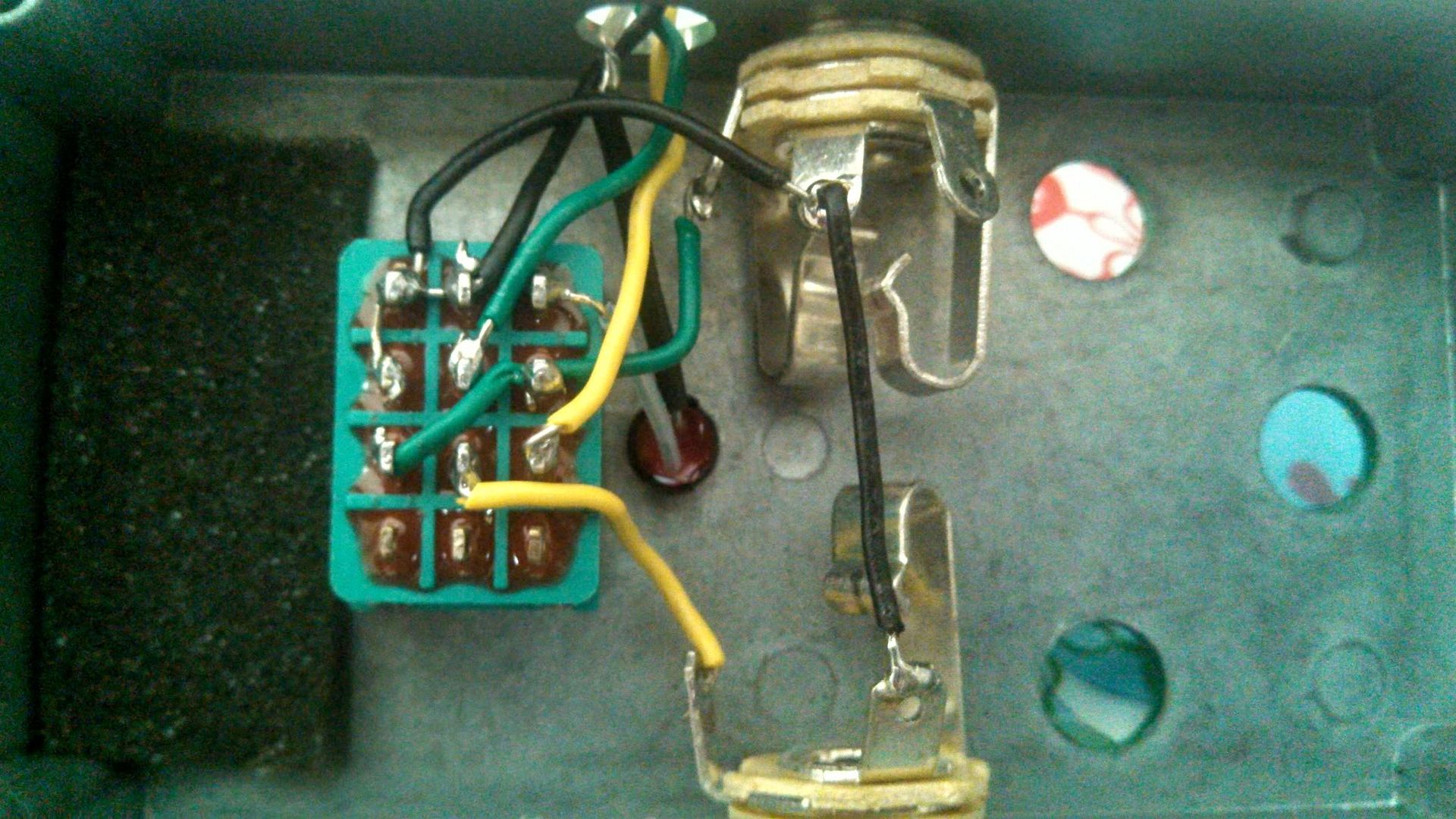
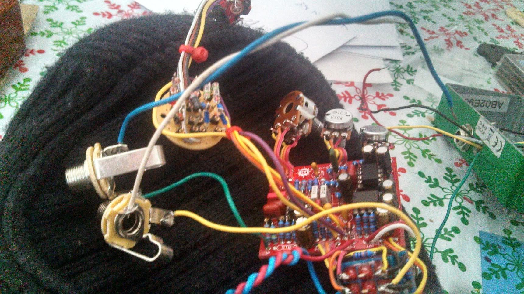
The guts of my testing rig.  Green is input Yellow is output.  Just True Bypass with an led.


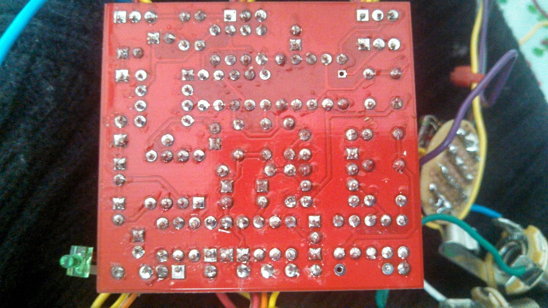
My Solder on the board


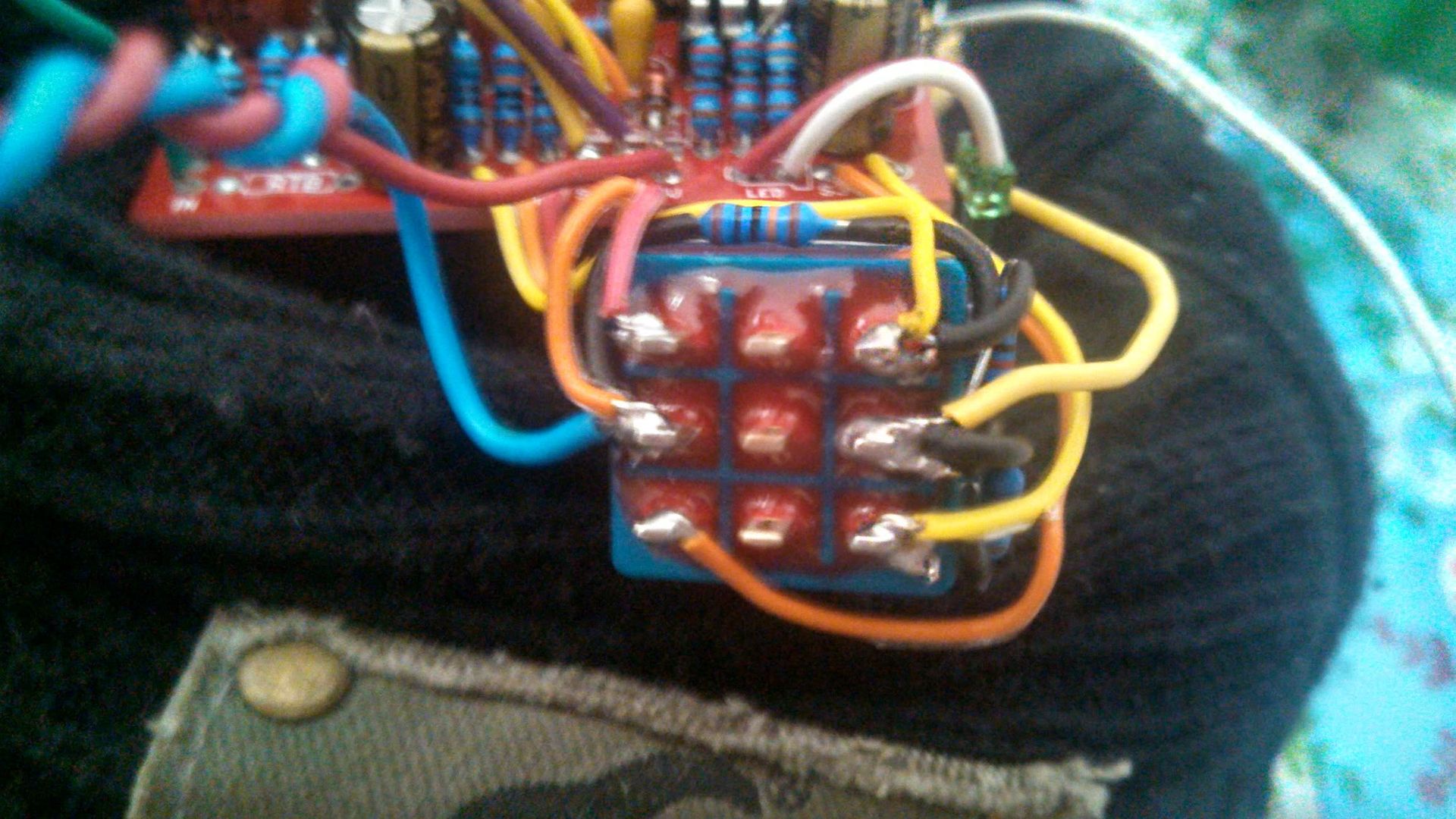
Output side of the Switch


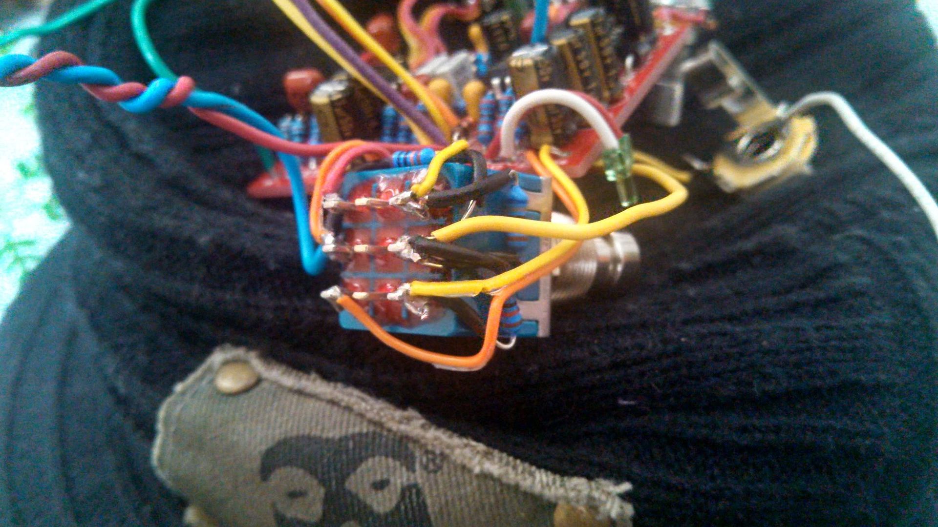
Input Side of the Switch. Blue goes to ground and red is 9v.


The Jacks, Blue and White are over sized ground leads to get back to the breadboard,
#2
          On my testing rig with a True bypass 3pdt in between .... Yes I was.  PS I wired it up for the buffered bypass.  When I installed the jacks all I have is an ungodly ground buzzzzz.

"B"
#3
          Ok, This makes me feel like the biggest noooob around.  I finally got around to building the Sunking V3 that I had purchased.  I included the clipping diode mod that gives you a tone of options.  With all of the pots, mods and what not & anything else that I thought I could do to to thoroughly confuse myself, I pit it on my testing rig and viola!  I had given birth to one of the mythical beasts here!   ;D

          Feeling proud of myself, I designed the box, drilled it , painted it and installed my new Sunking.  As I always do before I close up a box, I took it to the music room for a thorough break in.  I plugged it in and ........  no sound.  >:(

          So, I took it all out of the box and went back to the stage I knew it was working.  After unsoldering the input and output jacks and DC to put it back on the test rig, I didn't have high hopes that it was going to work  but .......  there was my awesome Sunking!  So I thought I must have made a noob mistake wiring the jacks and DC.  To defeat this I installed the Input and output jacks back on the pcb.

          OMG GROUND HUMMMMMMMMMMM.   All I have effectively done by doing this is remove the Input and Output jacks and 3PDt bypass switch of my testing rig.  While testing in this format I made sure to try one or the other and both Sleeve connections tied to ground to see if I was just missing a ground point.  Neither had any help.  ??? 

          Does anyone have any Ideas?  Thanks again for all of the wonderful searchable advice here.

"B"
#4
Open Discussion / Re: Cool Toggle switch and LED source
December 07, 2012, 04:16:27 PM

          I had to buy some of the 2mm leds.  Almost to the size that you wonder if it is a light or reflection from the pedal!  hahahahh

"B"
#5
General Questions / Re: amp kit II
December 02, 2012, 10:44:52 PM
+1 to the schem for the limiter. 

I'm ok ...... I can quit any time I want to ........ (Denial!!!)

5e3 in sight or Marshall 18 watter!!!
#6
Build Reports / Re: Lil' Green Watter!
November 30, 2012, 09:49:07 PM
I'd Be interested in a fabbed board!!!!

"B"
#7
Tech Help - Projects Page / Re: Bumble Bee No Effect
November 30, 2012, 09:44:34 PM
Bret608
          I thought about the battery clip shorting and checked it before i ran the last set of numbers, & just to make sure there was no doubt in my rig again I tested another project with it (Rainy Day Dist) and all is as it should be!!  I appreciate any angle though.

Electricstorm
          I will get to that method in the next day or so.  Thank you for the idea.

Again thanks guys, I'll solve this puzzle yet.

B
#8
Tech Help - Projects Page / Re: Bumble Bee No Effect
November 30, 2012, 08:24:19 AM
Jon,
          So I replaced c6 and d2.  Same result.  Something odd that I didn't think to check until this morning is that I get 1v when I measure the -9v pad and grnd pad (next to the in and out on the boardP.  I'm pretty sure that I should have the same voltage as my battery there.  Does that sound weird to you?

"B"
#9
Tech Help - Projects Page / Re: Bumble Bee No Effect
November 29, 2012, 05:49:41 PM
Jon,
         Thanks for looking into this again.  So would replacing D2 and C6 be a good starting place?

"B"
#10
Tech Help - Projects Page / Re: Bumble Bee No Effect
November 28, 2012, 05:47:33 PM
Jon, (and anyone for that matter)
          I have modified the original post to contain my current position in the Bumble Bee puzzle!
     Thanks again for looking at it!

"B"
#11
Tech Help - Projects Page / Bumble Bee No Effect
November 27, 2012, 09:08:38 PM
Hello all,
         I am perplexed that I seem to have the same signal when bypassed as when engaged with my Bumble Bee.  To Preface, I am not one of the fx wizards here on the forum, however the Bumble Bee is my 13th (yes lucky # 13) pedal build.

        I have gone over all of the solder joints countless times, cleaning and reflowing anything that might be suspect.  I have checked all of the Emitter, Base and Collector pin outs for all three transistors until I am blue in the face.  I have replaced the Input and output leads twice, thinking that some how I might have a stray hair wire touching that was sending input to output.

        I always put the pcb's on the breadboard testing rig before I box them up.  The rig is powered by a 9volt battery and I have checked it's voltage.

        My question at this point is one seeking advice.  Should I go the rout of the audio probe or start looking at voltages next.  This is my first build that I have run into this problem.  

        Usually if I don't have signal, I break out the audio probe and see where the last point the audio is present and work from that.  This time there IS audio at the output, it is just the same as when the effect is not on.  To make sure I was hearing the circuit, I disconnected the input, switched the effect on and there was no output.  Thus, I have verified that the problem is not in the switching of my test rig.  Any Ideas?  I'm sure this will lead to a DUOH! moment.  But I look at it as a puzzle to be solved and a lesson to be learned.  Any help is appreciated.

"B"

Edit:          Jon, The Pots do not change anything at this point.  I am using Chromesphere's Russian germanium transistors (ufo style) for Q1 (Current = 547va Leakage = 36va HFE = 56.7) and Q2 (Current = 566va Leakage = 24va HFE = 60.2) and a Russian tophat for Q3 (Current = 1445va Leakage = 214va HFE = 136.7).  I am totally slammed with Daddy duties today but will get voltages tonight when I get the kiddo's down.  Thanks again for the direction.


EDIT #2    After a little time with my audio probe and my radio shack  multi-meter I am even more confused.

           Leaving the output connected to the test box out, no matter where I place the input probe I get the same signal (un-effected).  When I reversed the process and left the Input connected to the test rig same thing!   I also get audio when I probe the c6 electro! I thought being the first thing in line with the power that is a little odd! I doesn't matter whether I have power or not during these tests, I tested both ways.  That brings me to my next conundrum

          I tested a 9v battery this am & it read 8.7volts by the time I had finished all of the testing it read 7.46.  All of these numbers have to be wrong
          Q1: .561
                .563
                .563
          Q2: .553
                .562
                .655
          Q3 .732
               .739
               .766
"B"

#12
Ok.

         Here I go. Voltage measured at the sag pad gave a -8.75v reading.  That's why I used it as the -9v in on the ggg board. Where I am completely lost is where "ground" is on the board (ggg)! I have the sinking feeling that I have grounded the -v somehow.  

:-\

B

All is working now!!  I had a poor solder joint from the Road Rage ground to the 9v jack!  Haste makes waste.
#13
Yes I had them in front of me the whole time.  This might explain what is going on inside.

Again thanks for looking at this.


B
#14
Jacob,
          Yes!   When I plug in the audio cables the power to the rest of the chain is disrupted.  All of the other "normal" pedals lose power and the Fuzz Face stays on  :-\

Thanks B
#15
I could use some help and understanding!

         I had another Roadrage at my disposal and wanted the Fuzz Face that I had built early on in this adventure to be able to sit on my board without a battery.  I followed the instructions in MB's Road Rage Doc wanting to have the Sag control.

         Without plugging audio in, Everything powered the way that it should.  Funny thing though, when I started rewiring the audio in's and outs It was like I had never added the Road Rage.  I have included GGG's layout here in the hopes that someone might be able to lend me a hand.

         ANY help in troubleshooting this issue would be greatly appreciated!

Thanks B