News:

Forum may be experiencing issues.

Main Menu
Menu

Show posts

This section allows you to view all posts made by this member. Note that you can only see posts made in areas you currently have access to.

Show posts Menu

Topics - mcasemo

#1
Build Reports / Screen Print Trials - Church Rat
November 20, 2019, 08:24:36 PM
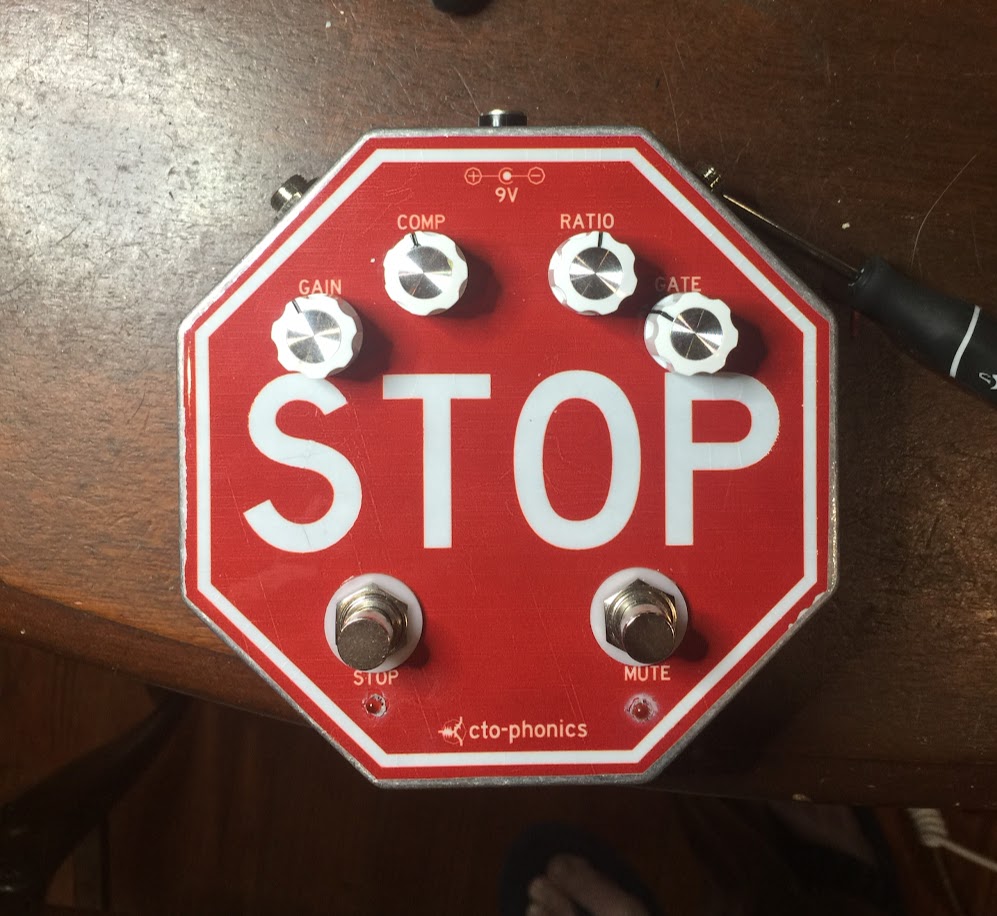
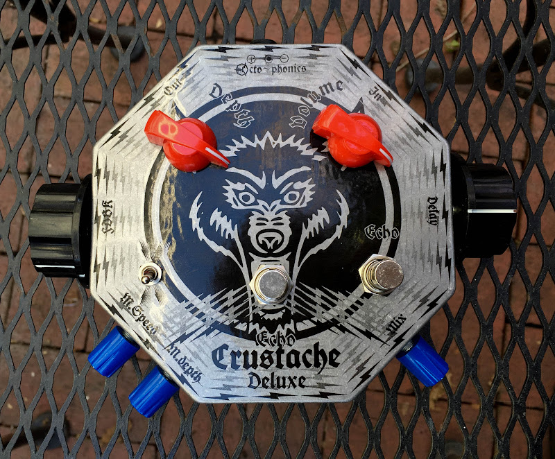
I did a couple of screens for t-shirts that worked out and wanted to try to do some enclosures after seeing some successes posted here (Jacquard ink).  I have one graphic (waterslide) that i thought would be good for screen printing, so I tried to modify the graphic to make the text more obvious and such, anyway, here are the results.   I scuff/brush the surface to get a brushed/bright textured look.   Lessons learned are to widen the text much more, figure out how to center/align better, use the right size squeegee.....    They came out pretty good, just need to clearcoat next and see if I can make the actual pedal :) .

I made the little fixture with MDF and a jig saw, and originally tried to use the enclosure back as a way to restrain the enclosure during printing, but it slid too much and made the graphic placement too unpredictable.   so moved to a spring loaded restraint, then had to shim to get to right height.

waterslide graphic here:
http://www.madbeanpedals.com/forum/index.php?topic=22138.msg217945#msg217945


#2
General Questions / AquaboyDX Question
May 02, 2019, 07:26:50 PM
I'm troubleshooting my Aquaboy Deluxe 2013 build, not yet ready to post a tech help post yet.   Short story, I have high pitched noise, thought it was clock noise, but after removing all the chips its still there.   

The weird thing is that it still passes dry signal, although a bit reduced, with all the chips not installed.  Is that possible?  Just wondering if that is what i should be troubleshooting now.  There is a transistor buffer before the LF353 buffers, could it push signal through the feedback resistors in the op amps stages without the op amps there?

Edit:  It works fine with all the chips in, just has the high pitched noise (just not sure of the source yet)
#3
Build Reports / STOP - AMZ Q&D Compressor 2
February 13, 2019, 04:59:16 PM
I wanted to make a noise gate to possibly use with the ROG Thunderbird, then a friend suggested the octagon/stop sign would be funny as a noise gate.  So looking for noise gates and found the AMZ Q&D 2, which is a compressor as well and still fits the stop sign joke and has a mute function.

It uses a SSM2166, which is for mic preamps or something, seems to work well.   Handing over to a friend to test out with ambient slide stuff and to test the noise gate (i have no noisy pedals around that work).   "Ratio" should be "Rotate" or "Threshold".  I got confused.

This is my first SMD soldering attempt, chip to adapter board, to stripboard layout.  Not sure i was built for SMD, haha

cheers


#4
I've built two Dig Dug 2's, one about a year ago, and just finished another.   Both strangely have an issue where sometimes it will go 8 steps when the odd number step sequences are selected.  Meaning for step switch on 1 it goes 8 steps, switch on 2 it goes 2, switch on 3 it goes 8, etc......  First time around i thought it was the switch, cleaned it, the put a new switch in and still same issue.  Now a year later, new switch, new chips, same thing.

Just wanted to check if anyone ever experience this?  I have a few more CD4017's I'm going to switch out, but wondering what could be causing it.  Maybe a different D3 to get a higher voltage to reset?
#5
I wanted to try adding stages to a bad stone / bloodstone.   I tried with the MFOS phaser and failed, figured i'd try here and fail again.

Is it possible to add 6 stages by adding 3 4558's and a CD4009, then just feeding them the same VB/VR and signal from the LFO?  Like this?   Or is there something going on with the pin 14/15 stage that i don't understand?


https://photos.app.goo.gl/94rdBhFgUavPtZtb8
#6
I made some PCBs for the ROG Thunderbird, being legit and following Brian Tremblay's licensing agreement (think i might sell a few).  I tried to follow good layout technique, but to be honest, all i know is to try to keep the power separate from the signal, then after a while of routing, that is out the door (I think i ran the Vcc right under one of the voltage diodes). 

First build sounded amazing, but had a high pitch noise, and the white noise was too much.  Tried shielding and that did not work, finally figured out I have bad batch of LT1054's (ebay) (5 KHz switching freq) and once i found a good charge pump, it was much more quiet.    I'm going to avoid charge pumps for a while, struggling with bad ones in a few other builds (although TC1044SPCA's at mouser are like $1 right now).

Anyway, this thing sounds awesome, and super loud.   Octagon enclosure, water slide decal, graphic I got from a "one sixth warrior" forum, a guy in korea made a 1/6 scale jimmy page with this suit and I found his suit graphic.  I wish i could still find the photos of it, it was insane, little Jimmy with little LP and pedal.  I'm trying to pay him as well if I sell them, but he's not responding.


#7
Build Reports / Dig Doug
July 29, 2017, 01:52:00 PM
Here is my completed dig dug 2, made for a friend who came across Brian's demo and really wanted one.  Searched for famous Doug's for a graphic, came up with Doug Henning.

After drilling, had no room vertically, the board is jammed up against the stompswitch, which is jammed up against the octagon.  Had some trouble with the step switch, think i got some drill shavings in it, it would only work on odd numbers, even would go full 8 steps.  Think i have it clean now.

Put the rez and filter pots on the bottom.  The trem side seems lower gain, i may add a resistor in line with the trim to bump it up a bit.

Love this thing, very fun.

Mark


#8
Build Reports / Feral Errol Fuzzes
July 06, 2017, 10:07:48 PM
A couple of fuzzes I made for a friend with his dog (Chinese Crested, Errol) as the graphic.  First is a 3 knob tonebender, which included a makeshift dying battery knob (not yet added) using a current limiter, LM334Z. Trying to experiment with the EM Distortion Box spectra knob (Charles R. Fischer).  Didn't really work on this, or I did it wrong. Stripboard and tried to pot mount it, so all bunched up at the top of the big octagon.   Clear waterslide decal trying black ink background, never really works right trying to make the printer do full black.  And my fingerprints are preserved i think.

Next is a fuzz dogg PCB, univox superfuzz.  So awesome.  Did the germanium, silicon and no clipping option.   Tone switch scoops the mids.  Love this thing, and you can see I learned how to do graphics a little better (not my photo, stole it from one of his gifted friends).  Sorry no guts of this one

Trying to start posting more stuff I've finished, failed at lots of experiments, but its all fun.


#9
Open Discussion / RIP Ray Wilson
July 23, 2016, 10:34:57 PM
Looks like Ray Wilson has died.  Sorry to be the guy to post it, just saw the news and didn't see it here, i know there are many synth enthusiasts here.

I recently started into the synth stuff, so have spent a lot of time on his site reading his awesome write-ups of how each module/project works.  Made the subcommander, and emailed him a few times and got responses within the hour, hand drawn redlines on the schematic for mods.  Such an inspiration. 

http://www.synthtopia.com/content/2016/07/23/ray-wilson-of-music-from-outer-space-has-died/
#10
Build Reports / Steal This Pedal - Sunking 2015
July 04, 2016, 06:35:17 PM
Here is my Sunking 2015 with patriotic colors and Abbie Hoffman tribute.  It cuts out when gain is around 3 O'clock with a weird whine, then comes back, so I'm going to start swapping/checking the charge pump.   Clipping diodes are very subtle to me (on/off/on with red led's and 1N34A), but I'm tone deaf, going to let some friends play it. 

#11
Build Reports / Fuzzler and Psycho Kriller
April 16, 2016, 04:39:42 PM
I've been making PCB's (seeed, itead) for a few different ideas, one was adding a LFO to a mutron iii.  I did one with the naughty fish, and made my own lfo daughter board.  Then i made a psycho lfo (pseudo random lfo) with it and it sounded pretty cool.  I posted some of it, but lost in the crash.  Psycho Kriller, krill is a filter.  Corny.  Also lost was that pedal as i tore it apart trying to get it to work properly.  So I made some PCB's with it integrated, with envelope, lfo, and psycho lfo mode on a rotary switch.  Glide and Depth of the LFO are on the side, and Rate is on a big knob for foot control.  Have to put in the led's in the krill's eyes.  On the first one was pretty cool having one light up and the other doing the psycho bleep thing.  Still have a glitch with the normal range of the mutron iii and still want to tweak the gains and speeds of each lfo stage for the random mode.

Next is a 4 fuzz pedal that run all in parallel into a mixer, Fuzzler.  All you can eat fuzz, sizzler rip off graphic. The Fuzzes (all silicon) are Jordan Bosstone, the Os' Mutantes (deadpool), WEM Pep Box Rush, and a Fuzzrite.  It is switchable to have the Bosston feed the Os'Mutantes and to have the Fuzzrite feed the Pep box.    PEP box was weird, the trim pot in the schematic would smoke if you turn it all the way one way, could not figure that out, they always still worked, friend called that "the sizzle".  Surprised it all worked otherwise.  The Bosstone and Fuzzrite are lower volume, think i need to muck with the mixer gains for them to even it out.  Going to hand this off to some friends to see if it's any useful.  Probably should put some more radically different sounding fuzzes in here.  The PEP can be kinda gatey, so that's sorta neat to have it gate out and have other fuzzes still sustain.

I PCB mounted everything I could and I now know why you don't want to do that.  Lining up everything causes you to stress the board.  So I have to figure out what i want to set the position, and open up the holes on most of the rest.  After dropping the fuzzler in the box with graphics, it stopped working, got to go heat up some joints and see what happened.


#12
I was battling some switch noise on a PCB i made, selmer buzztone into a ZPMII / Deep blue delay.  Thought I had it licked with a bad solder joint, but...

I still get a noise after the switch on of the delay, with fuzz already on, at the time of the delay. So Fuzz on, hit delay, XX ms later little step/sound.  This is more prominent with more fuzz and volume.  Pin 7 and 8 on the PT2399 increase in voltage with the volume/gain of the fuzz.  Switch the fuzz off, they go to similar values (0.6ish).    Is this normal?  I don't know what they do.  Pin 7 goes to higher voltage at the same time of the noise.  Pin 8 switches immediately. 

Any thoughts or ideas welcome. 

Looking at moodring, and having built one, wondering if the true bypass setting that may cause more switch noise is similar, or expected.  I don't want to rip this one apart if i can make it better essentially, haha. 
#13
Saw the moodring posts and remembered I posted this one before the crash.  Original Proco Rat, no mods with moodring.  I mixed up the left to right order of the thing, so the switches are labeled wrong essentially.  And I ran the reverb into the rat the first time around and my friend was like, sounds kinda off, so fixed that and it sounds much better (but i'm tone deaf and have no rhythm, so what do i know).  waterslide decal, but sure would like to etch this (stupid difficult etching).


#14
I'm having trouble with my Honeydripper Rev 1.1.2, non-2015 version, using CA3080's.  I'm getting filtered sounds, but the envelop is not sweeping the filter.

I've reflowed and scraped solder flux and checked for bridges.  I have a USB scope and can follow a signal through IC1 and IC5.   The signal at pin 8 of IC1 is a tall squarish wave, after that it looks like a sine wave signal of similar amplitude as the input signal being inverted out of phase.  Not sure what I'm looking for.  I can see nothing on pin 5 of the CA3080's.

Maybe my substitutions are to blame?   I used a TC1044SPCA for the charge pump and connected pins 1 and 8.  I used TL074's in place of the LM324.  R21 is 2k and C2 is 1n
Pictures and voltages below, any help is appreciated, or anything specific I can look for on the scope

   IC1
Pin   TL074
1   4.95
2   5.11
3   5.06
4   16.36
5   5.12
6   5.12
7   5.12
8   2.1
9   5.11
10   5.12
11   0
12   5.1
13   5.1
14   5.05
   
   IC2
Pin   CA380
1   ignore
2   5.1
3   5.1
4   0
5   0.68
6   5.12
7   16.36
8   ignore
   
   IC3
Pin   CA380
1   ignore
2   5.1
3   5.1
4   0
5   0.663
6   5.1
7   16.36
8   ignore
   
   IC4
Pin   4558
1   5.07
2   5.12
3   5.1
4   0
5   5.1
6   5.12
7   5.11
8   16.37
   
   IC5
Pin   TL074
1   1.7
2   1.7
3   1.8
4   16.36
5   4.89
6   5.44
7   1.4
8   4.35
9   2.8
10   2.8
11   0
12   2.8
13   2.8
14   2.8
   
   IC6
Pin   TC1044SPCA
1   9.35
2   4.5
3   0
4   137 mv
5   27 mv
6   5.28
7   6.53
8   9.36


#15
Looking for some guidance on the mini mixer (ggg, rg keen) and using with 4 fuzzes in parallel.  Wanted to have a 4 in 1 fuzz pedal where all run to a mixer in parallel.  Also, my schematic has it where you can stack two together, but we can ignore that part of it and assume all run into the mixer's 4 channels.  This may be pretty useless, but thought it might be fun to experiment. 

One question, could each of the volume knobs on each of the fuzzes (currently a fuzzrite, wem pep box rush, os mutantes, and jordan bosstone) serve as the mixer input controls? 

Next question, would anyone expect tone loss without the use of buffers after the fuzzes?  I've read straight guitar signals into mixers can have issue, just not smart enough about these transistor fuzzes and output impedance.

Finally, for a master volume control, could i use the 100k pot on the first stage of the dual op amp, or should it be on the second stage to control gain?

Any advice is appreciated.  I know I can just breadboard this up and test it all, but thought I would pick your brains first. 


#16
I posted one of these previously (lost in the crash), but made another one for my kids school fundraiser with their mascot logo on it.  So thought i'd re-post.  It's a selmer buzztone with a delay that is based off of the ZPMII, but with the echobase delay time and modulation.  Side mount delay and feedback for foot control, and side mount mix, mod depth and mod speed to preserve graphic space.  This was my second attempt at PCB making, only messed up one thing on the board.  Did Seeed this time, so I got 8 more to make.

My kids go to a french curriculum school here in New Orleans, and their mascot is a Loup Garou (or Rougarou https://en.wikipedia.org/wiki/Rougarou) kind of a french/cajun werewolf.  It's a charter school, so they have lots of fundraisers, so i'm donating it for one of the auctions.


#17
Build Reports / Dream Smasher - RM and Delay
April 26, 2015, 06:50:39 PM
The pedal hobby got me hooked up with some musicians in New Orleans, and one guy i've been fortunate to become friends with knows lots of people (Gary Wrong, Gary Wrong Group, Wizzard Sleeve, Vatican Dagger....).  I sell a pedal every so often at a local shop and made a orange squeezer that he tried and loved how it drove his amp.  So we tried out rangemasters and he decided he wanted to make a "signature pedal" of sorts to sell along with his albums and shirts....  Ended up with rangemaster into a deep blue delay-ish delay with rate knob on the side to control with your foot.  I put a switch inboard for caps options for the RM.

Fortunately he can sell stuff, so making as many as i can, but unfortunately it get's tiresome making the same thing over and over.  But was interesting to make 5 at a time and tweak my normal process.  For instance, for tagboards, i created a 0.1" grid in powerpoint and put the cut pattern on it and print it out, align them with the stripboard and mark the cut locations by letting a marker bleed through.  Other thing i finally realized that helps, when putting in the in, out, 9v, ground, switch, pot wires to the board, strip enough insulation so you can sorta hook them to stay in place.  I used to do one at a time, but this suddenly lets me put them all in and set up to solder once.  Maybe this is an obvious thing, but took me a long time to figure it out, haha.

anyway, messy wiring below, and a video Gary Wrong made with the prototype.


#18
General Questions / Tubes, need help
April 05, 2015, 05:58:09 PM
A good friends father passed away a while back, he was an electronics guy, tv circuits and such early on, raytheon control systems, apollo mission controls guy.  did not get to meet him.  he has been clearing out his house and gave me the second batch of tubes he found.

Can anyone identify if these are worth keeping for projects?  I have a separate box of unboxed tubes that i need to pull and identify.

i'll list these out if you can't see them

#19
Build Reports / Rangemaster magic
March 14, 2015, 08:10:00 PM
Not a complete build report......I'm not much of a guitar player because i'm no good, but really love pedal making and and making stuff others can use on stage or in recordings.  So it took me a while to learn the magic of the rangemaster, I don't have any huge amps or anything, but after a few rounds with a friend, we got around to trying a rangemaster to push his JCM800.  I guess this is sorta classic, but so fun to see how something so simple does the trick.

#20
General Questions / Sea Urchin 1uf caps
March 10, 2015, 06:13:48 PM
I'm building several sea urchin delays for combo boxes, I failed to order 1uf electrolytic caps, and don't have enough 1uf film caps.  Question is:  would an alternative value work here?  They seem to be associated with the in/out buffers/amps, just wondering if there is anything special with the 1uf value.

Thanks
Mark