News:

Forum may be experiencing issues.

Main Menu
Menu

Show posts

This section allows you to view all posts made by this member. Note that you can only see posts made in areas you currently have access to.

Show posts Menu

Topics - LateCentury

#1
Build Reports / Aion Cirrus build "Annuit Cœptis"
April 03, 2017, 08:07:18 PM
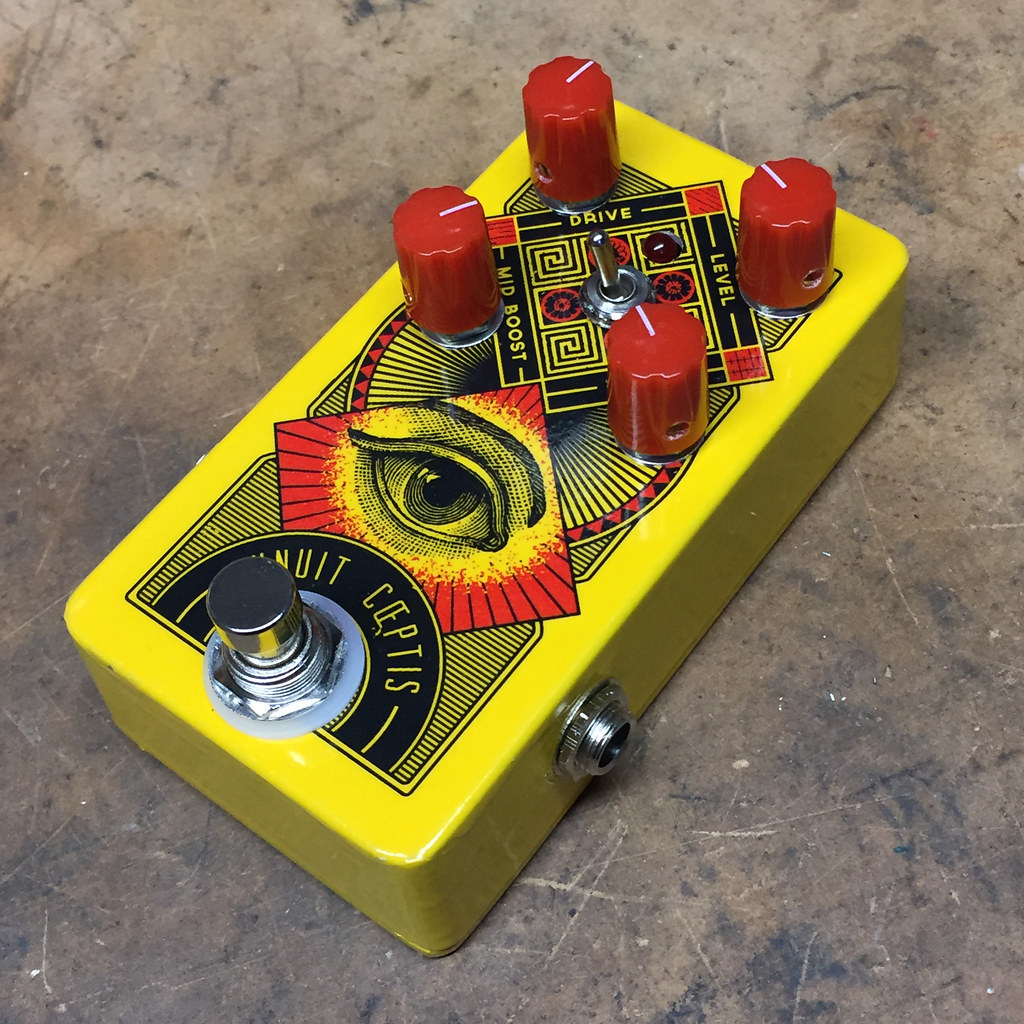
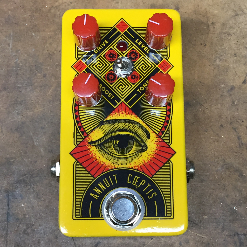
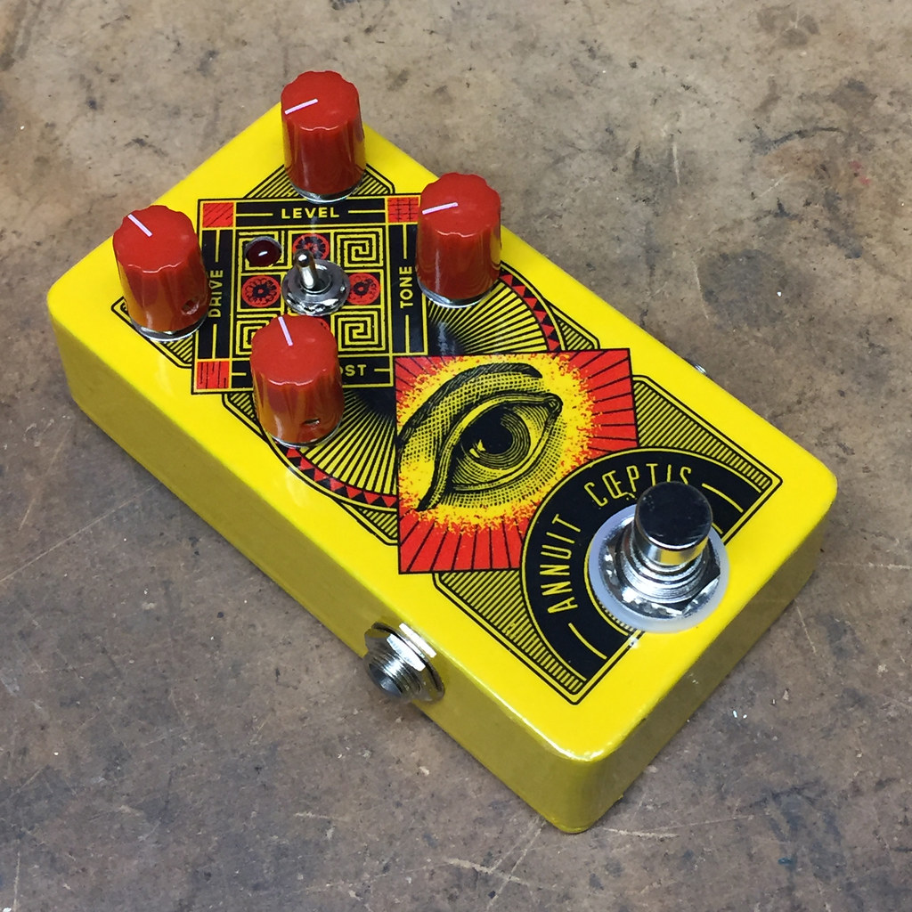
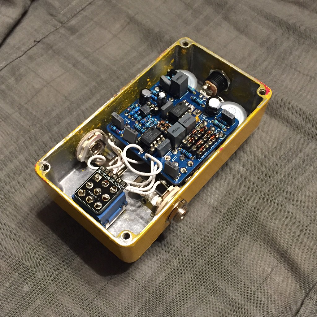
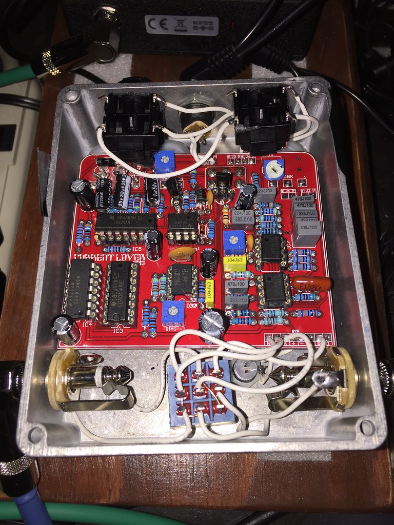
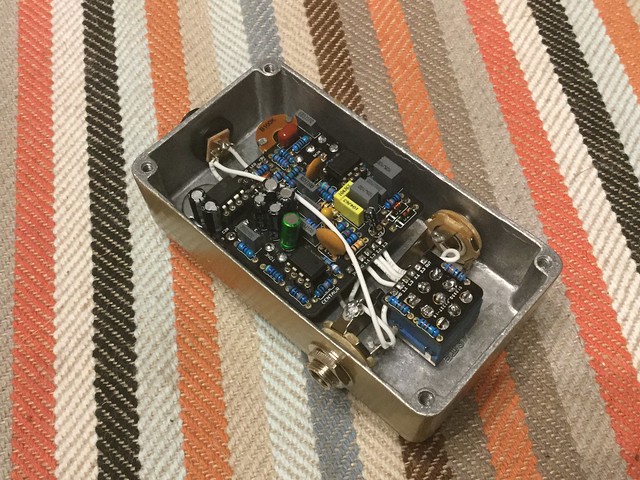
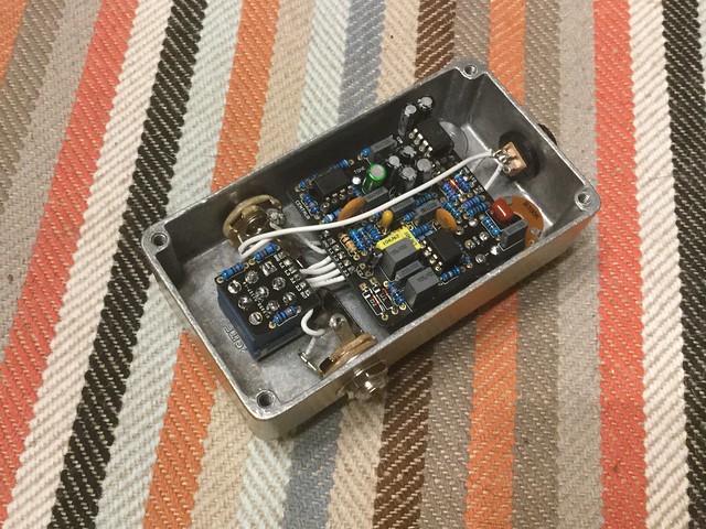
I finally boxed up another project tonight. This is the Aion Cirrus, their take on the Super Tube Screamer with the different clipping options and the ability to toggle between other types of overdrives. I used the SD-1 as the other option. It sounds pretty great with a lot of reverb, you can really nail some David Gilmore type tones. I think I might  switch the clipping the other way around, I'm getting a little crackle when there is a lot of treble. The inspiration for the enclosure design is really just random things. Oh and yes, I realize in the photo the wiring is backwards for the input/output. I fixed it after I realized there was no sound. Also, the inside of the enclosure is a mess due to a stupid painting disaster. Out of sight, out of mind.  ::)


#2
Build Reports / Gravity Wave build: "Medusa"
April 02, 2017, 10:03:33 AM
The only modifications I made were a capacitor change and a resistor change based on people's feedback in another thread. I haven't really played around with it a whole lot yet, but the depth seems to not really make much of an appearance until about 50%. Other than that, I'm pleased!


#3
So, I'm building the Smoothie and I don't have any 470k resistors. If I were to stack two 1m resistors together bringing it to 500k, would that work as a substitute? I would need to do this on R10, R11 and R14. Are there any negatives about fudging the numbers this much?

I would need to do the same for the 3m9. I have a 10m and a 4m7, bringing it to 3m12. Would that work better over just using a 4m7 as a substitute?
#4
I made an etch of this little guy and thought I would try to cram it in a 1590LB.

Bypass works but no signal when clicked on. I don't really know where to begin to troubleshoot. The only sound I can get is a little AM radio when I touch the back of R6-R9  8)

#5
Tech Help - Projects Page / Testing rig woes.
February 27, 2017, 12:23:24 PM
I thought I would finally make myself a testing rig after having too many problems with boxing a non-working build first. Yeah, I know.  :-[ 
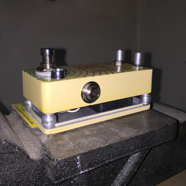
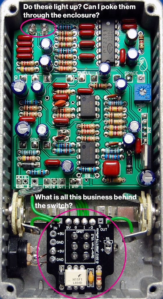
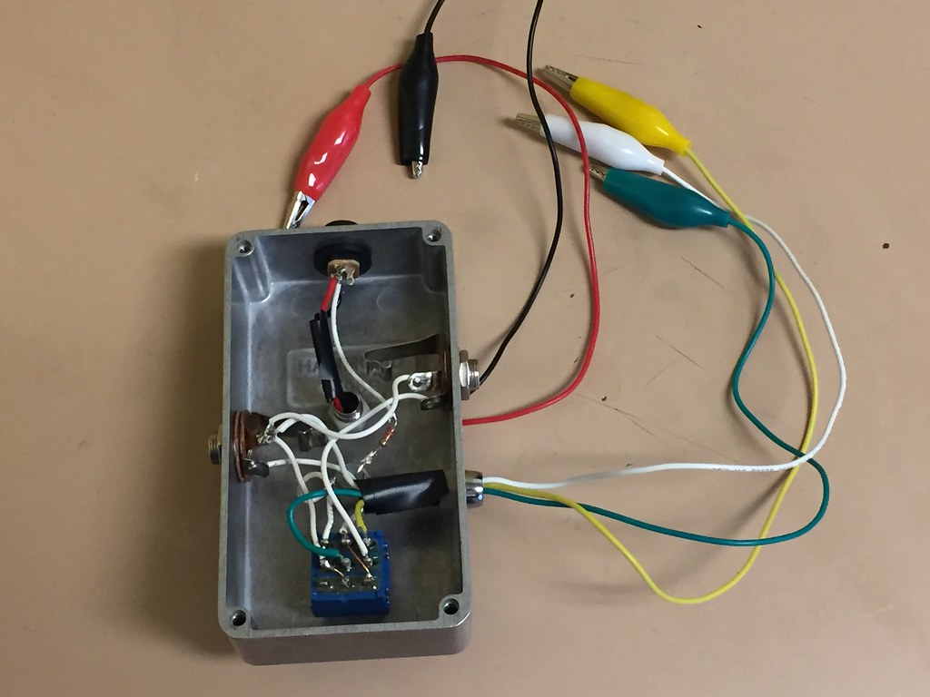
I cannibalized an A/B switch box I made as the case. I thought I had everything correct here but it does not seem to work. It passes the bypass signal fine, but when powering up and switching on a board that should be work, I get nothing. I've traced the wires more times than I can count and it looks like it SHOULD work! I've even tested the switch for continuity. All pins show continuity between middle-top and middle-bottom.

I've got an alligator clip for the board input, board output and ground, then positive and ground for the jack. The boards that I have tested power up and I can touch the L wire from the board to the resistor in the case and It lights up. Am I missing anything?


#6
This build went very smooth up until I decided to box it before I rocked it.  ::) The bypass signal is crystal clear, but when you kick it on it goes silent. I've quadruple checked that every wire is going where it needs to. The optional fx loop is connected the way its supposed to with the switch jacks. The LED lights up, but not the LFO LED. I would think that at least SOME sound would come through.


The close pic of the capacitors is showing a little hack I made to pull them back to make room for the fx loop jacks. I de-soldered them from the board, and re-soldered longer legs to those 3. The diode is not touching the legs and the LFO LED its not either. I don't know if that would matter.

Here are the voltages. The numbers in bold are the ones that appear massively different from the documentation.

Voltage at power jack: 9.31

IC1 4558
1. 4.66
2. 4.66
3. 2.32
4. 0
5. 4.53
6. 4.53
7. 4.39
8. 9.63

IC 2 MN3007
1. 9.03
2. 4.48
3. 0
4. 0
5. 0
6. 4.48
7. 2.56
8. 2.57

IC CD409
1. 9.02
2. 4.48
3. 4.47
4. 4.47
5. 4.49
6. 4.46
7. 4.49
8. 0
9. 4.47
10. 4.48
11. 4.47
12. 4.48
13. 0
14. 4.47
15. 4.48
16. 0

IC4 CD4013
1. 4.48
2. 4.48
3. 7.33
4. 0
5. 4.49
6. 0
7. 0
8. 0
9. 0
10. 0
11. 0
12. 9.03
13. 0
14. 9.02

IC LM324
1. .5~7.5
2. 4.02
3. 2~5
4. 9.01
5. 0
6. 0
7. 7.74
8. 1.03
9. 1.03
10. 0
11. 4.01
12. ~
13. 4.09
14. 3.5~4.5

IC6 LM311
1. 0
2. 4.96
3. 3.42
4. 0
5. 9.03
6. 9.03
7. 7.32
8. 9.03

IC7 4558
1. 4.51
2. 4.51
3. 4.51
4. 0
5. 4.01
6. 4.52
7. 4.52
8. 9.01

Thanks in advance! This is so frustrating!
#7
Build Reports / Aion Refractor build: Hippocampus
January 16, 2017, 07:22:48 PM
This was probably my best build yet. I think I've more or less found the best method of transferring laser prints with polyurethane. More than anything I'm glad the switch, jacks and pcb aren't fighting for space after having dealt with 1590a's and G's. I think I might have to stick with B's. Oh, and it sounds great! No trouble shooting, worked the first time.


#8
Build Reports / Moodring build: Adrift
November 01, 2016, 09:39:21 AM
This is pretty much the stock configuration of the Moodring pedal crammed into a pre-drilled, discounted 125B box from pedalpartsplus. I started this around February and am just now finishing it. This being my 3rd pedal build, but first one started, I'm pretty happy with it. I've learned a lot about the proper order of doing certain things to make my life easier.  :D  
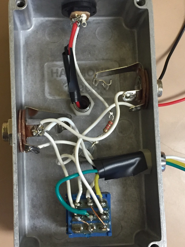
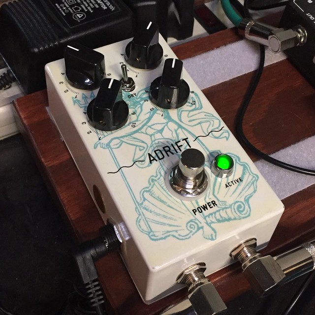
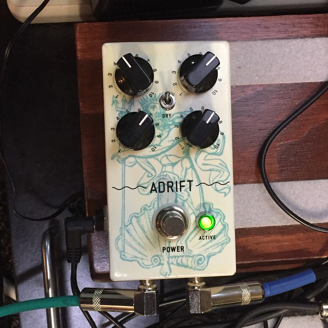
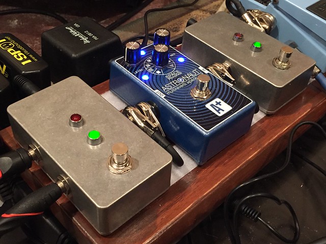
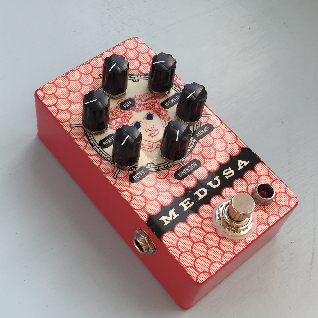
Its definitely a weird one. I'm not quite sure how the dry switch is supposed to sound when you switch 'off' the dry, but it seems very quiet. I'm going to have to get creative to find ways to use it.


#9
Mods / 1590G enclosure space-increasing mod
June 17, 2016, 06:20:44 AM
This is a mod I came up with to increase space in one of my 1590G builds. This one is the Ping. I just couldn't cram it all in especially with the reverb tank, so I decided to get creative and make the enclosure taller.  I'm not completely finished. I think I might fashion some plastic or maybe even thin balsa wood strips to tuck inside to cover the opening from dust and dirt. What I'm using here are aluminum alloy bicycle brake cable end buttons, drilled out a little larger and longer screws (from light switch covers or outlets I think?) I like the look a lot, kinda makes me want to try to find knobs that have a similar shape.

#10
Build Reports / Pink Whale - Snarkdoodle etching
June 16, 2016, 08:25:12 AM
Here is my first attempt at squeeeeeezing a build into a 1590a box. Man, every millimeter counts. I'm not even going to post a pic of how messy the insides are. The enclosure design transfer was done using the color laser printout/acrylic polyurethane method.

It sounds pretty good, except I'm getting kind of a subtle choppy decay when I let the strings ring out. No idea what that could be, but since I have this crammed in there so tightly and it being my first ever pcb etching I'm surprised it works at all!

#11
Hey there...

I just tried to make this:


Only with a momentary switch instead of a typical 3pdt. What happened when I powered it up was that the switch was on and carrying the feedback loop signal (with a delay pedal in the loop), only when I pressed the switch, the signal cut out and it started feeding back the leftover delay signal repeats. So, technically, the feedback loop works... but I don't understand why its cutting my signal. I tried eliminating spdt switch and connecting the 1 terminal of the pot to the center lug. Same result.

Am I misunderstanding how momentary switches function? They shouldn't cut the signal out, right?
#12
Open Discussion / Unsure about a feedback looper
April 09, 2016, 09:56:32 PM
Hey all.  So, obviously, each pedal build starts out with a particular 'need'... /sarcasm

I'm thinking about building a simple momentary feedback looper pedal but I'm not sure it will do exactly what I want it to do. Ideally, I'd like to boost the feedback on a tape echo pedal I have, momentarily.

I use two delay pedals on my board: a Supa Puss and a Hotone Tape Eko.  Currently, I find myself rolling the feedback knob with my foot to add some "extra space" in song transitions or breakdowns. I've heard you can utilize an expression pedal with the Supa Puss, but it only changes the delay time. What I'd like to do is increase the feedback level.

My question is, for the effect I'm looking for, would a feedback looper do anything for me? I've tried to find videos that show what people have done with them, but I haven't seen anything that I'm looking for.
#13
So I just finished building my Ping. All components in place, wires hooked up. Plugged it in and it passes a clear signal to the amp. Once I turn on the switch, the LED lights up but it makes what I would call a sputtering static sound and the guitar signal is cut off completely. I'm going through and checking all the wires, solder bridges that I can see, basically everything I can get at without taking off the reverb brick.

Does anyone have any ideas as to what this sound could be indicating?
#14
Build Reports / First noob project... switches!
March 04, 2016, 04:51:39 PM
I thought I should start out with something pretty basic before I dive right in. I play bass and guitar in a band and I recently built a new pedal board to house both effects. I wanted to utilize my Shift Line Astronaut reverb pedal for both and switch between the signal paths.  Here's what i came up with... green: guitar, red:bass

#15
I'm planning on getting very ambitious and having this will be my first build... I've been watching a ton of videos and reading loads of stuff on these forums, so far I think I have a relatively good handle on the basics.  Couple of questions though... hopefully the (stolen) image will be self explanatory:

1. The two red/diffused LED's on D3 and D4, what exactly do they do? My main question is if they just act as diodes or if they actually light up. I'd like to poke them through the enclosure and incorporate them into my graphics if they do.

2. I've seen several completed Moodrings both with and without this extra board here, attached to the switch. What purpose does that serve?

Thanks!