News:

Forum may be experiencing issues.

Main Menu
Menu

Show posts

This section allows you to view all posts made by this member. Note that you can only see posts made in areas you currently have access to.

Show posts Menu

Messages - JackSkellington

#106
Build Reports / Re: slow gear
March 21, 2020, 02:08:33 AM
Good!
I tried to build it on veroboard layout from Sabrotone, but for some reason it sounds clean without any effects though the voltage are ok. I replaced even some transtistors bought from two different shop. But I never find any mistake.
#107
I'm from Italy. ;)
This is crazyness. You hear professional in the tv says that alerted zone in China are solving somehow the contagion problem with the isolation, so now we know that's a solution. When somebody ask if we have to do the same thing the answer is... no. We have to do it, but just a bit, less extreme. Nonsense. Maybe we can't do it for many reason, but there's no logic in the speech we hear. It's like if they tell us to wash just the left hand.

I hope what we are doing now in Italy can help us, but I'm not a really good feeling about it.
#108
I'll work on a gain pot or similar configuration using a voltage divider resistors after the first stage. :)

It' a bit difficult try just the recovery stage but I'd say it sounds clean. It's almost the same of the first stage, maybe with a slight difference impedance because the two resistors 43k/430k in the first stage and 100k/1M in the second.
When I pass through the whole schematic I don't have any attenuateion of the signal after the first stage, probably was this to caused the distortion.

What you said about the EQ and the factor 10 has sense to me! ProTone Body Rot II has 330nF instead 22nF (well a bit bigger) and 4,7nF instead 470pF. a 2.2k resistor instead a 33k (again, a bit too smaller), and 20k for Treble, 2k for Mid (those are pretty), and a 50k for Bass pot (this is smaller).
Pots value doesn't help too much, but if I scale the eq value parts like you tell me early, do you think I can still talk of Marshall Tonestack?

(I see some pedal use the same Marshall or Fender eq. The Krank Distortus Maximus is the same circuit of the Body Rot II, but it has the orignal values of a Marshall Tonestack.)
#109
All Italy is in lockdown. We can't go out except for necessity.
#110
Thank you.
The 4.3k forms a high pass filter, but I tried it and it really cut volume/distortion, too. I tried 1k, but was too much volume cut, a 4.3 k leaves just a little bit distortion to the peak.
Anyway, I have to try a voltage divider adding a resistor in serie to the C8, creating a sort of gain pot. Right?
I didn't want to change R10 because with a switch (not in the schematic) I bypass the eq and its recovery stage to link directly to the Volume pot, for a more transparent mode of the boost. I have to try to keep about the same output between with and without eq.

What do you mean about the eq?
I emulated different compoents values of the eq, basic on the Protone Body Rot II. It could be better. I'd like the idea to build a kind of Marshall EQ Boost, but, I don't know why it doesn't work right.
#111
General Questions / Marshall Tonestack sounds weird
March 09, 2020, 08:49:11 AM
Hello guys. New projects, new questions.

I'm playing around a booster with a Marshall Tonestack. As you can see is a LPB-1 in front with the eq and another LPB-1 as recovery stage.


It's clear enough, I hope. This is a simplified version of my whole schematic that has just a low pass filter in the end with an hard clipping, even if this doesn't sound so good.
The 4.3k before the eq is to avoid too much signal in the second stage, else it distorted. I want it pretty clean.

Hard clipping aside, I like it, it works, but the eq is not so good in this configuration, and I don't know why. The schematic is correct, but how I can see in in the emulation of the software and in my built prototype, indeed I tried it, the Treble pot doesn't cut treble; I got a kind of flat response of the high frequency; I can get a pretty sparkle sound even with the Treble at minimum.
Bass pot has just a little range.
Mid pot make a flat response of the mid at maximum and a treble cut at minimum. Depends from the Treble setting.
My intention is to use the Marshall Tonestack, so I don't want to change it. Anyway, I guess it never will sound good.

Did you ever tried something like this?
#112
So, R12 and R13 will not change the effect. If that's correct I'll try it! :)
#113
I built a Tremulus Lune some years ago using a tagboard veroboard layout.
I want to build another one, but I have a doubt. I used in my first one the LFO red LED 5mm as blinking LED. It's always on. I included it because I followed the layout and I liked the idea. And I used a red LED because I saw other people used that color.
I can't understand if the blinking LED is necessary to the circuit. Can I remove it? This was just a theorical hypothesis, because I would like to know if that LED doesn't count with the main effect circuit maybe I can change the color or adjust even the brightness if I keep it. I see a 1k resistor (R13) to the ground from the negative side of the LED. Maybe I can change that like we do with a staus LED?

This is the schematic.


Thansk!
#114
Thank you. I built using 1590A box just sometime in the last months, and every time I have to measure it like you with very very care.
I converted the inch in mm.

Footswitch: 11,1mm from the base
Power Jack: 11,1mm from the top
Input jack: 14,3mm from the top; 15,1mm from the top
Output jack: 14,3mm from the top; 23,8mm from the top
#115
Hello, I don't know how much people are still following this thread, but...
Here's the original Smash Drive schematic:


I'm building the version without tone stack, of course.
I'm not sure if this pedal is never built by someone, but I'm trying.
First thing I did is to test it on the breadboard, and I got a little issue. The circuit had a lot of volume, I can hear the pedal even if my amp was at zero volume. And the sound was pretty fuzzy, a bit splatty and gated.
This is the second time I get something like this using a LM386 chip on my breadboard. I'm starting to think that the LM386 gets some problem with the breadboards, or with my breadboard.
Anyway, I draw a veroboard layout.


So I built it, and it worked. But I didn't include now the 100R in line to the 9v, nor the 100nF ceramic cap. Then I moved the 100uF a column at right. And the 10uF is soldered exactly there, but moved "asymettrically". This movement is because the space on the board.
The sound was ok, no fuzzy or weird.
I based the taper of the pots, or maybe just supposed those, on some information I found on ti or on other similar projects (for example the Lovepedal Black
Magic). But I could misunderstood something, I'm going to tell why.
I tried a 5k linear pot as Drive pot and 500k linear as Volume pot.
Testing the circuit I found that I got a jump loud volume when I open a little bit the Volume. And the Drive pot start from a overdriven sound at minimum setting until an aggressive and grit distortion as I expected a bit from this chip. But the distortion raise up quickly when the pot is almost all at clockwise. Too drastically.

I replaced the 500k linear pot with a 500k log pot, and the volume works a bit better. But I guess it's still too much loud. A casual flying resistor, 5.1k or 10k or 20k... I don't remember, between the output and the ground helps to tame the volume. I'll find out a good value.

About the the Drive control. When the pot is at minimum the resistance between lugs 1 & 2 and the lug 3 is high, so the distortion is low. At maximum setting there's no resistance between those lugs and the distortion is high. I need something that decrease faster the resistance between the lugs 2 and 3, so If I'm not wrong I need a rev log pot, 5k or maybe smaller?

The bad thing is that the two 9mm pots I'm ordered are linear.
#116
Hello. Forget about the SHO, then I solved the problem with some common method.

I'm working again on the same Woolly Mammoth I got the squeal and nothing changed. I just repeated some experiments with some changed value.
I really like this fuzz, but the issue is really annoying, it's almost done, but not completely as I wished. I'm using a 100uF cap across 9v and the ground and a 1N5817 in line to the 9v.
The circuit is ok in the most setting, but the problem come out with the fuzz over 9/10, a bit more at the higher setting of the EQ, and perhaps with some parts changed that boost some mid/high frequencies. At least, I can't hear the whine when I play or when I don't play, but just when the guitar volume is off.
So probably I can live with this problem, afterall. Just I can't like this kind of issue.
Of course with the battery I got zero whine.

I tried to make it on breadboard, with the same transistors (2N3904) and some of the same parts. The problem was there.
My last hope is that I will solve it completely after I soldered the parts on the board, and boxed up (even if I'm not sure this is a shielding problem). Maybe I could try an alternative layout, like the tagboard one, but this doesn't have the 100uF between the 9v and the ground. My built got a crazy squeal without it, I can add it easily.

Help me if you can! ;)
#117
New little update. Nothing distortion pedal, again, but I'm trying to work soon about it. I'm wating some materials I ordered. ;)
I just want to say, after the SHO as boost pedal, I just finished the IC Buffer in the 1590A box.

Meanwhile, I'm looking some mild overdrive, too. I can read all this thread where I got some suggestion about the distortion, but I found them not very distorted.

I just want to say that I will build it on veroboard, or maybe on perfboard.
Of course, I accept new suggestion! ;)
#118
Quote from: madbean on October 31, 2019, 05:57:51 AM
The CFH is a very hacky effort. It's just a static SHO with clipping diodes and a tone control. But, it sounds quite good so I'm going to do a run of them. Also, CFH stands for Crotch Fire Hurricane.

Hi, I found the Crotch Fire Hurricane, and I'm really curious about it, but I can't fine any sample or demo.
I have none BS170 now to try it, but I played around with the circuit. I emulate it with a software to see the frequencies, I think it's a little circuit with some possible mods. ;)

I changed the tone pot with another simple tone used in some pedal (OCD for example) for a wide range of treble control. We could use a Gain pot like the original SHO or, if the crackle don't like, we could use a Crackle Not Ok Gain pot, and see how they sound.

Meanwhile, did someone built it or try it? Who has some demo, please.
#119
General Questions / Re: Boss fz-2 owner question
January 16, 2020, 12:58:27 AM
Great! ;)

Excuse me, what do you mean with this? «I have this working using basically jellybeans too.» ???
#120
Some little news. I'm still not building anything, I have to order some materials. Probably I'll try the Smash Drive based on the LM386 anyway, but I found something different that I could like more.
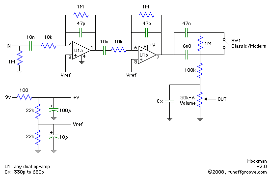
The Mockman 2.0 by ROG, http://www.runoffgroove.com/mockman.html. I can build the perfboard layout on the ROG web site, or use this one: http://effectslayouts.blogspot.com/2018/05/run-off-groove-mockman-20.html
If I am good enough I guess I can fit it in a 1590A box.


It's a one-knob efffect, Volume pot only, but I'd like to have a gain control. I'm more comfortable with non-inverting input stage so I have to try, because I not sure how they could work, some solutions to get a good gain control.

1. Pre-Gain: a pot at the begin of the circuit, like the guitar's volume pot.
2a. In the first opamp feedback, with a basic resistor (33k?) and a 1M pot (linear or log?).
2b. The same thing but in the second opamp feedback stage?
3. How I see in a early version of the Mockman, a 100k linear pot in line in the input.