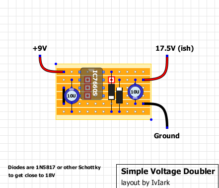
News:

Forum may be experiencing issues.

Main Menu
Menu

Show posts

This section allows you to view all posts made by this member. Note that you can only see posts made in areas you currently have access to.

Show posts Menu

Messages - JackSkellington

#256
Build Reports / Re: OCD....
September 27, 2018, 12:27:47 AM
I drawn this:


I have to say that the connections of the switch aren't verified, but should be ok, they have just to change the value of the original values.

Though it doesn't answer completely to your question it could be useful, anyway.
#257
General Questions / Re: Charge Pump: a bit of confusion
September 16, 2018, 01:26:59 AM
Just because I got a piece of stripboard slighly smaller than what I need for this layout I drawn the it again.
I moved the jumper that make to go the pin 3 to the ground and I moved a cut.

None of these two layouts are verified, but they shoud be ok because the original one is really similar.

#258
General Questions / Re: Charge Pump: a bit of confusion
September 14, 2018, 07:10:10 AM
Here's the modded layout with a jumper makes even the pin 5 grounded.


Thanks! ;)
#259
General Questions / Re: Charge Pump: a bit of confusion
September 13, 2018, 12:37:30 AM
Quote from: alanp on September 12, 2018, 10:51:25 PM
Pin 5 in the GCFX schematic you've shown is also attached to ground -- if you look, it's wired to the same GND point as Pin 3.

Yeah, I meant right this. The veroboard layout has the pin 5 isolated, in the Aeon (Tight Metal) schematic the pin 5 is grounded.

Quote from: reddesert on September 13, 2018, 12:06:01 AM
Page 8 of the data sheet, left column: explanation of how the circuit works to use switches on a high-frequency cycle to charge an external capacitor and prevent it from discharging, and discussion of technical considerations of how the switching transistors are biased to avoid latching up. Page 8 right column do's and don'ts, point 7: "User should ensure that the output (pin 5) does not go more positive than GND (pin 3). Device latch-up will occur under these conditions."

In the voltage doubler application, we aren't using the V_out (pin 5) that is used for the negative voltage output. The do's and don'ts clearly suggest that it should be tied to ground. If it floats and is not tied to ground, the circuit may work, until something unexpected happens and it latches up, and then it won't work (and the user will probably say "My charge pump IC is bad," mis-diagnosing the problem).

«If it floats and is not tied to ground, the circuit may work». That MAY worry me a bit. :P

There's even Sabrotone layout:

But this HAS the pin 5 grounded.

It's slightly bigger than the other, and it has the 100uF and 1N4001 extra parts. I assume I can omit them, right? The Tight metal layout already has them.

But I guess I can settle with the tagboard layout and to add just a jumper from the pin 5 and the ground stripe, a shortest jumper in the column between the diode and the cap.
Is that correct?
#260
General Questions / Re: Charge Pump: a bit of confusion
September 12, 2018, 01:37:04 PM
Thanks for the datasheet.
That kind of connection causes the doubt. Why in that layout the pin 5 are isolated? And that layout is verified and used. ???
#261
General Questions / Charge Pump: a bit of confusion
September 12, 2018, 01:55:06 AM
Hi, everybody!

I'm going to build the Amptweaker Tight Metal, but the layout I found doesn't have the charge pump, so I have to build a daugherboard.
I bought some ICL7660SCPA, I want to build something based on it.

I never used a charge pump, but I always thought the following veroboard layout was simple and good:


Of course, I compared it with some ICL7660S layout. Some of them include some extra parts like a 100uF and/or a 1N400X diode, as filter in the power supply. But the layout of the Tight Metal I have to use already has this accessories parts, and I guess I don't need of them.

And now my doubt about the circuit. I see in the charge pump layout that the pin 5 goes nowhere, so it's isolated. But in some other layout, as some schematic, pin 5 is connected (with the pin 3) to the ground. Why in this layout it isn't so?

Here's the schematic of the Tight Metal by Grind Customs with a charge pump section similar to the veroboard layout, except where pin 5 and pin 3 are connected together, and both go to the ground:


Should I consider to put a jumper to connect the ICL7660S pin 5 to the ground like the schematic?
#262
I could order the MMBFJ201, eventually, from Tayda, just because they are cheaper than the ones from Musikding.
I'm not talking about my Phase 90, but for any other project.

Meanwhile, I ordered a quartet of 2N5952. Not cheap, but it will work for sure.
#263
Thanks guys. I knew that BB Mod. I tried a 220R and a 10uF.
The Fat Rat add a 6.8uF in parallel to the 2.2uF. Indeed, I tried to replace the 2.2uF with a 10uF.
I noticed just the usually tame of the highs.

I can't try again all these. Next time I should try harder, or I'll let it go.
#264
Quote from: midwayfair on September 05, 2018, 07:47:53 AM
[...]
You can boost the base as much as you're boosting everything else by making C7 220uF. You'll boost literally every frequency. You might as well remove R7 and C6 now as they aren't doing anything. If you turn the treble cut all the way up, ta-da, you have a bass booster. Of course, now you sound like you're playing underwater, but you did ask for a bass booster ...

I would like to increase the bass without cut the treble (or the gain) this is the problem.

Quote from: marmora on September 05, 2018, 04:54:40 PM
http://baritones.tumblr.com/post/92511266453/darrell-rants-about-the-proco-rat-and-the-ruetz

Thanks for the link. I tried some mods like that, but the all of them are pretty subtle about the increasing of the bass. Rather those was a cut treble.
#265
Thank you very much, I'll try to take a look. ;)
Unfortunately, it's not a very simple solution I was thinking.
#266
Some clue how I could do it? ???

Please? :D
#267
I don't know if I like the blend mod. So the Rat really seems "bass unboostable"?

But the Fat Rat version has a bass boost, some demos show it works pretty fine.
I heard that it adds a 6.8uF in parallel to the C6 4.7uF, thing I tried replace C6 with a 10uF, but... it's not a really bass boost. :(
#268
Hi! With my second Rat building I tried some tricks I read around here and there to get more bass from this pedal.

I tried with my first Rat the Ruetz mod with the pot control (replacing the R6 47R with a 1k Linear pot).
Now I tried to replace the C7 2.2uF with a 10uF. Then I back with the stock caps.
Then I replace the C6 4.7uF with a 10uF, and even the R7 560R with a 220R.
Nothing of that gets more bass, I got just a slightly dull sound, but this is not a Fat/Bass Boost mod I mean.
I guess it's very hard to get more bass from this circuit!

Who knows the real trick to get more bass?

Thanks!
#269
Quote from: destro on August 23, 2018, 08:41:32 AM
Form my experience the 1n34s from Tayda have tested on my multimeter have been in the 2.7/2.8 range. Could just be the batches I've received on a few occasions....good luck!

Hi destro. I'm sorry, perhaps I missed something. What do you mean? What is 2.7/2.8 range?

Quote from: jubal81 on August 23, 2018, 07:29:11 AM
Best thing to do is socket and test with your ears.

Yes, probably I'll do. It's just to know how this pedal works.
Anyway, I bought a pair of D9E from Musikding and, of course, I forgot the 1N34As from Tayda! ;D
So, I'll have wait some weeks to build the Klon and I'll socket the diodes. I'm going to try D9E, 1N270 and... what about 1N60P?
#270
I just want to be sure if the 1N34As Tayda are fine and accuracy for the Klon.