News:

Forum may be experiencing issues.

Main Menu
Menu

Show posts

This section allows you to view all posts made by this member. Note that you can only see posts made in areas you currently have access to.

Show posts Menu

Topics - Obie bong kanobie

#1
General Questions / aion titan not working
January 10, 2017, 05:59:44 PM
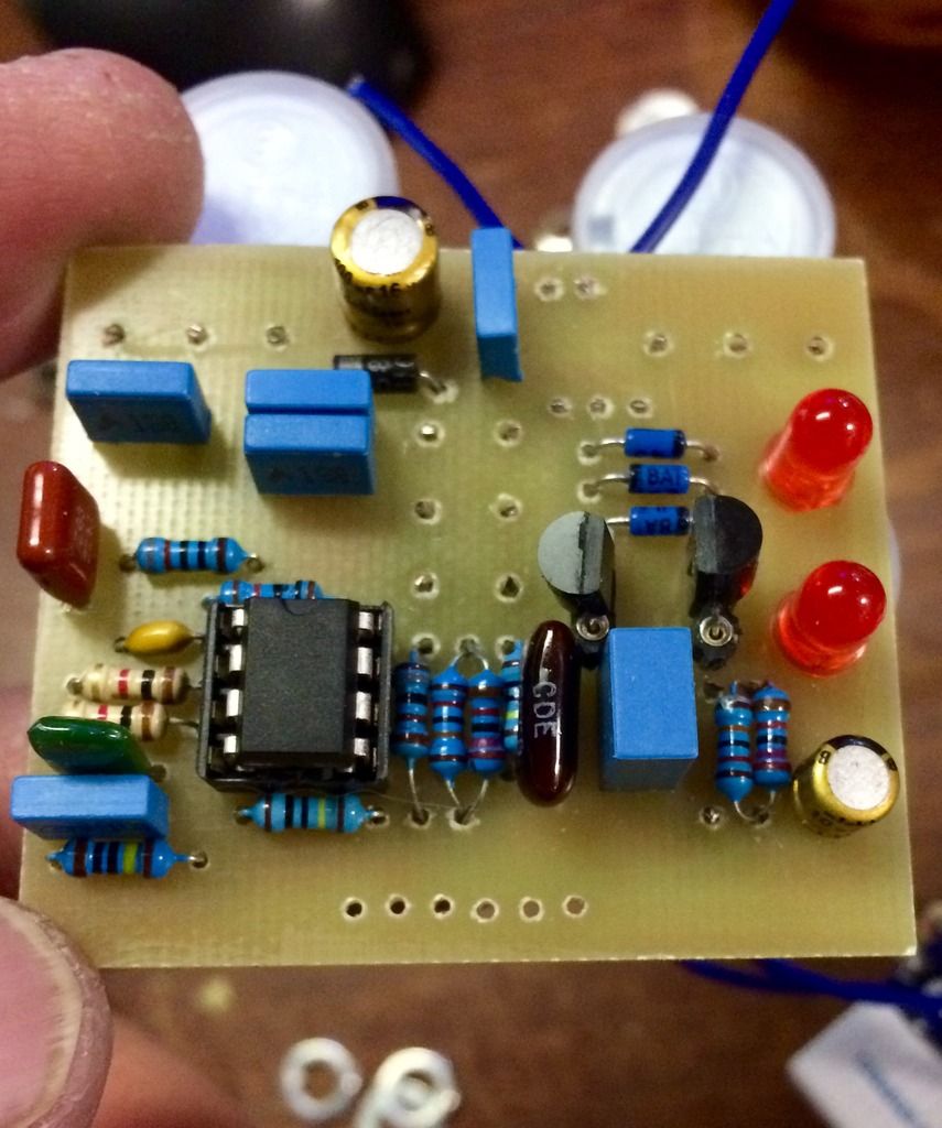
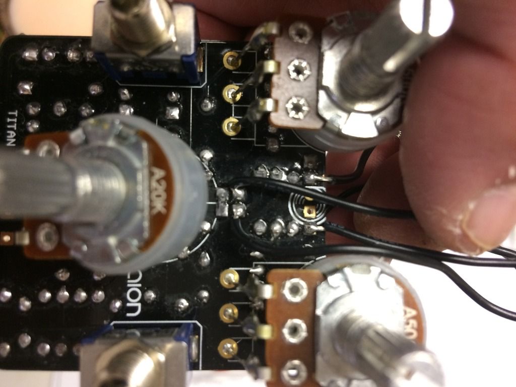
ok so my voltages with no charge pump and ic in is
1-1.4 2-1.4 3-1.3 4- 0 5- .9 6- 1.3 7- 1.3 8- 2

with no ic's
socket ic1   1- 0 2- 0 3-1 4- 0 5- 2 6- 1 7- 1 8- 4.5

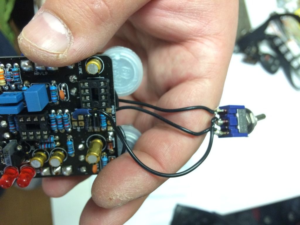
the 9/18v connection is on a switch   how I wired the switch was the bottom two squares go to lug 2 and top left square go to lug 1 and top right square goes to lug 3

I got these numbers with an 8v battery supplying power and I've also checked for shorts and bridges


#2
Tech Help - Projects Page / turnabout
January 06, 2017, 10:22:07 AM
ok, so the LEDs on my madbean turn about keeps flashing on and off, when I touch pin three to take voltages they glow constantly as well all I have hooked up are the pots and the clipping switch.  I also put resistor 8 on a switch so it goes between 470ohms and 1k8 

my voltages from an 8.26 battery

1-4.3(sometimes it reads 1.45?)
2-3.81
3-3.69( they didn't glow this time?)
4-0
5-4.02
6-4.02
7-4.00
8-8.03


#3
opamp voltages are all at half voltage, as expected  but as I touch the PCB it starts to glow on and off, I've built tons that work but I have two of them now doing this(all turnabouts)      the only mod I've done was resistor 8 on a switch (470 ohm and 1.8k)  wanted to see if it would have the same effect as the OCD hp lp switch as its basically the same idea, figured it was worth a try lol


#4
ok so my voltages are normal on all the other pins except pin 1 which is 1.4v and pin 2 starts at 3.6v and drops down to 2.6 as I hold my probe to it (7.9v battery supply)

ill post some pictures asap, I've reflowed the solder and checked for any bridges as well as swapping out opamps
#5
Ok so I've finished the pedal but the sound is really gated. I used micro electronics bc109 transistors and I did check the pin outs before installing them( I have no sockets left right now)

Could someone please verify if that's the issue.  Voltages are Q1 E.58 B 1.0 C 1.6. Q2 E1.0 B 1.7 C 5.8.  Q3 E .6 B 1.2 C7.5


#6
ok so i was checking over my voltages and they go as follows

IC1
1-4.42
2-4.46
3-4.28
4-0
5-4.52
6-4.52
7-4.55
8-9.41

IC2
1-0
2-5.07
3-5.02
4-0
5-0
6-5.04
7-9.42
8-0


ill post a picture as well
#7
I'm unsure of how to connect r3 to vb on the breadboard   

I'm so sorry I forgot the schematic. My minds all over the place
#8
Ok so the out resistor on the klon buffer is 560ohm I only have 510ohms.  I wired it to be a always on effect so it's hard for me to tell if it's working ok like this or not.  Can this work temporally and what is it going to effect.  The output impedance?  I'm a newbie sorry
#9
Ok so the output resistor on the klon buffer is 560ohms and I only had a 510ohm resistor.  What will the side effects be and can this work until the right part arrives      It's built But I didn't put it in a 3pdt so it's a always on effect and not that easy to notice a difference really
#10
Ok so I'm an idiot, I have worked with vero and built my first two pedals and then went to mod my tube screamer 💡 Great idea in concept except I held my iron to the pad for to long and lifted part of the trace. It's the 4.7k  resistor and 20nf input cap. Looks to my newbie eyes that it's the VR section of each component that got lifted. There connected on the underside so that's how I managed to kill two birds with one stone.  If anyone knows what else I can point to point wire them to I'd be really grateful.  Or the easiest way to fix my mistake.  I'm trying to go through the schematic and fine components I could but it's hard for me I think the 4.7 k can be connected to the 510k resistor(if it's close enough) because it also goes to VR. or I'm I sadly mistaken about how to fix it. I'll attach a picture and I appreciate anyone who takes the time out of there day to post suggestions
#11
I'm getting noise when I plug it in and have it in bypass and I also get that same noise out of the output jack you get when you touch a patch cord when plugged in.   Assuming that means that a signal is making it there. The input however there's nothing when I touch it when it's plugged in.   I check the entire circuit last night against the schematic and went from component to component check continuity. This is my 5th build but first project I've ever wired up because the wire took forever to arrive in the mail.   Any advice, tips and help is greatly appreciated