The only sub made was the 1.2k resistor. I had to use two 2.4k resistors in parallel
- Welcome to madbeanpedals::forum.
This section allows you to view all posts made by this member. Note that you can only see posts made in areas you currently have access to.
#16
Tech Help - Projects Page / Re: pigbutt not working, can someone please help troubleshoot
August 29, 2016, 06:12:09 PM #17
Tech Help - Projects Page / Re: Colorsound Overdriver only really works with gain on full
August 29, 2016, 06:08:52 PM
I have a issue with mine as well, but mine sounds really gated and only works if I strum really hard. What could that be, I'll try to post some voltages after your problem is fixed so I don't hijack your thread
#18
Tech Help - Projects Page / Re: pigbutt not working, can someone please help troubleshoot
August 29, 2016, 06:04:06 PM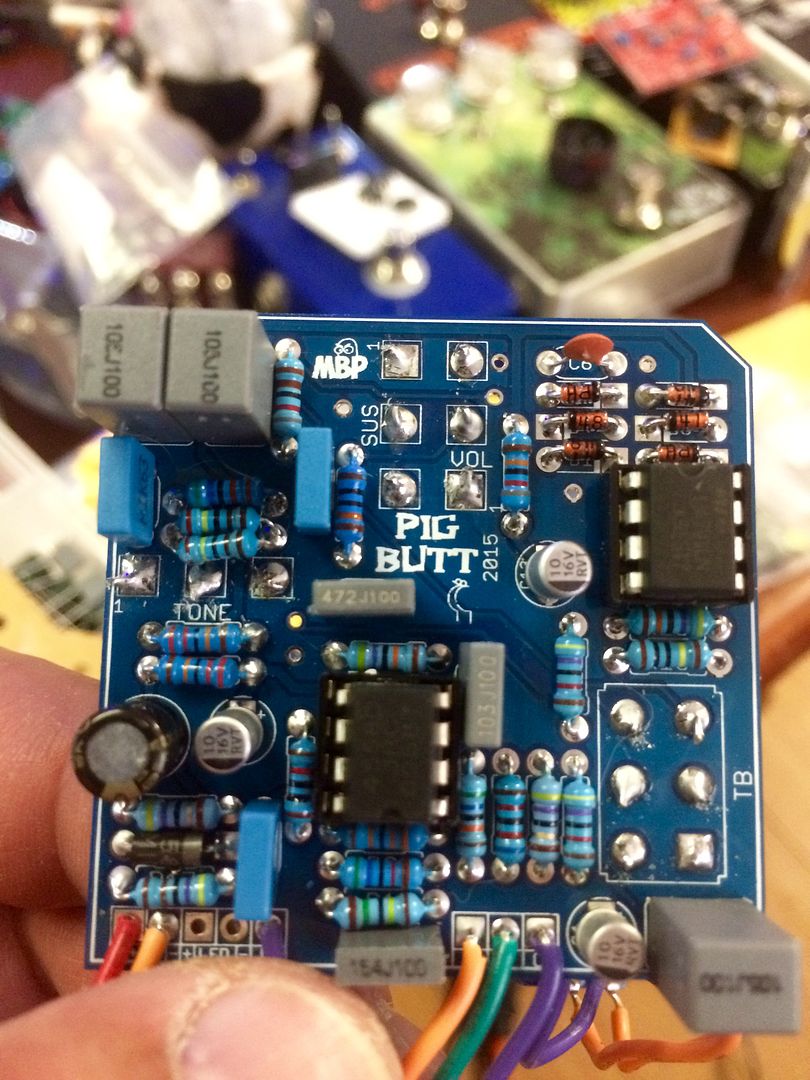
#19
Tech Help - Projects Page / pigbutt not working, can someone please help troubleshoot
August 29, 2016, 05:37:03 PM
ok so i was checking over my voltages and they go as follows
IC1
1-4.42
2-4.46
3-4.28
4-0
5-4.52
6-4.52
7-4.55
8-9.41
IC2
1-0
2-5.07
3-5.02
4-0
5-0
6-5.04
7-9.42
8-0
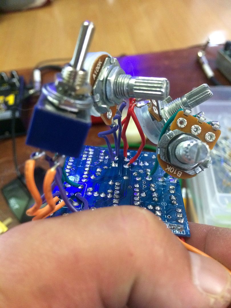
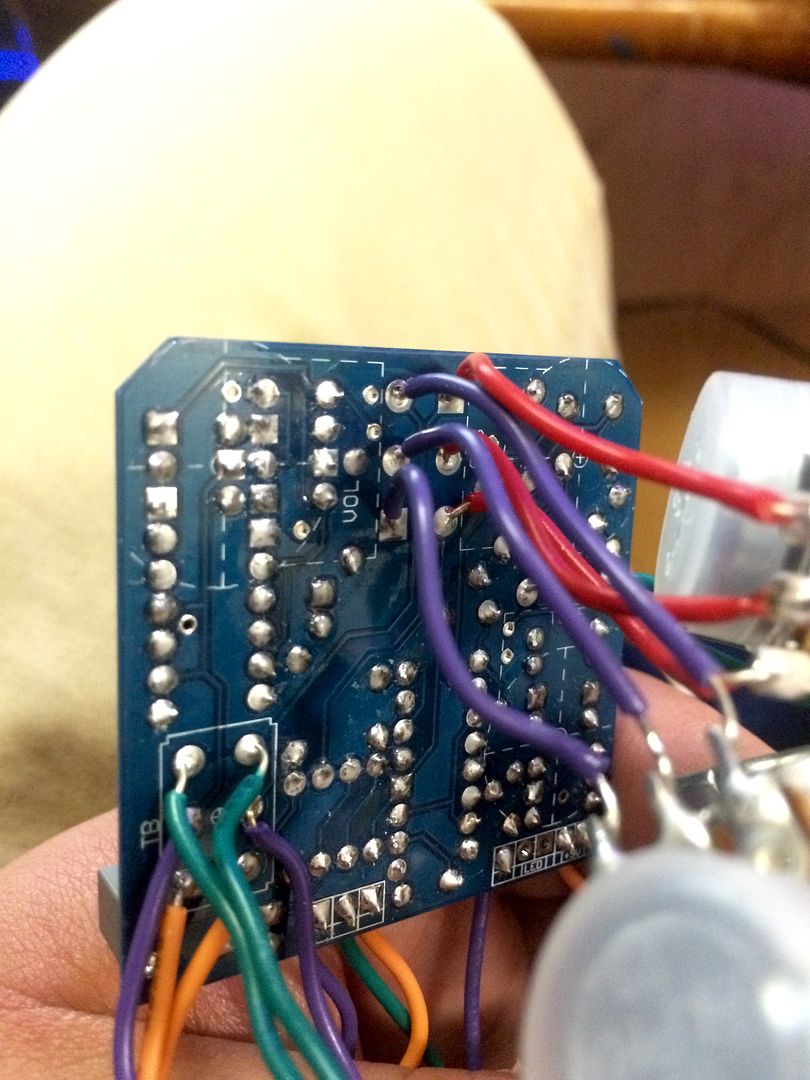
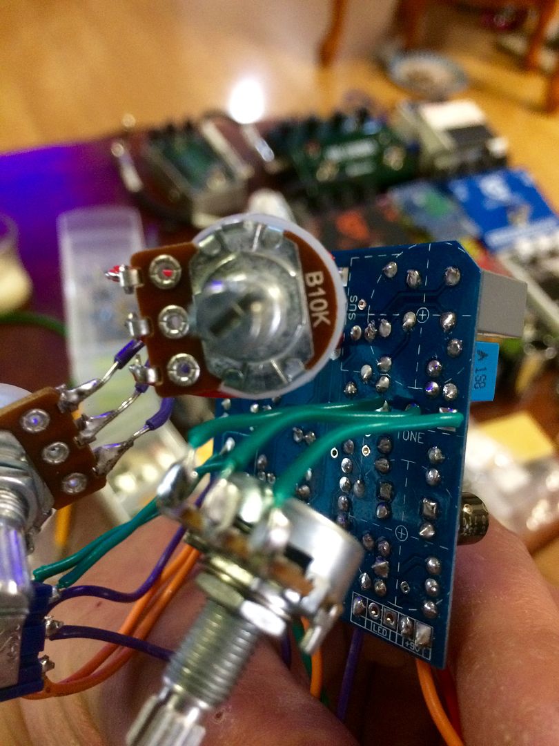
ill post a picture as well
IC1
1-4.42
2-4.46
3-4.28
4-0
5-4.52
6-4.52
7-4.55
8-9.41
IC2
1-0
2-5.07
3-5.02
4-0
5-0
6-5.04
7-9.42
8-0
ill post a picture as well
#20
Open Discussion / Re: Newbie question about building from schematic on a breadboard
June 14, 2016, 04:03:21 AM
Perfect thank you so much for all your help. I've seen it before on schematic's before but was always building from vero so never really figured out anything to be honest except how to assemble the board/wiring. It's a step up from ordering a kit but still not great for trying to learn what everything does and how it works. I find IMO breadboarding should be one of the first things anyone does
#21
Open Discussion / Newbie question about building from schematic on a breadboard
June 13, 2016, 11:03:18 PM
I'm unsure of how to connect r3 to vb on the breadboard
I'm so sorry I forgot the schematic. My minds all over the place
I'm so sorry I forgot the schematic. My minds all over the place
#22
General Questions / Re: Quick klon buffer resistor substitution question
June 13, 2016, 05:52:42 PM
Thanks so much I really appreciate the help
#23
General Questions / Klon buffer part substitution question
June 11, 2016, 08:47:39 PM
Ok so the out resistor on the klon buffer is 560ohm I only have 510ohms. I wired it to be a always on effect so it's hard for me to tell if it's working ok like this or not. Can this work temporally and what is it going to effect. The output impedance? I'm a newbie sorry
#24
General Questions / Quick klon buffer resistor substitution question
June 11, 2016, 08:44:13 PM
Ok so the output resistor on the klon buffer is 560ohms and I only had a 510ohm resistor. What will the side effects be and can this work until the right part arrives It's built But I didn't put it in a 3pdt so it's a always on effect and not that easy to notice a difference really
#25
How Do I? Beginner's Paradise. / Re: Setting vero layout: did i do this wrong
June 02, 2016, 06:36:51 PM
Hey sorry to write on a old topic but I was wondering how your build turned out in the end. There's so much to learn at first so don't beat yourself up for any mistakes you make because it's a opportunity to learn troubleshooting skills which eventually no matter how good you are your going to need. Hope you ended up with a working effect and keep rockin 🤘
#26
General Questions / Re: I violated my tube screamer and now need someone to save my ass
May 30, 2016, 12:48:27 AM
Ok so I made the input cap 100nf and that resistor like I said 2.2k Something is wrong though because I'm only getting a signal if I strum really hard. Any ideas should I take some voltages for you guys? I'll modify this comment when I'm finished writing down the voltages and add them to here
Ic pin 8 9.70v, 7 4.88v 6 4.87v, 5 4.87, 4 0.00v, 3 4.80, 2 5.80, 1 4.90v
Ic pin 8 9.70v, 7 4.88v 6 4.87v, 5 4.87, 4 0.00v, 3 4.80, 2 5.80, 1 4.90v
#27
General Questions / Re: I violated my tube screamer and now need someone to save my ass
May 29, 2016, 11:08:38 PM
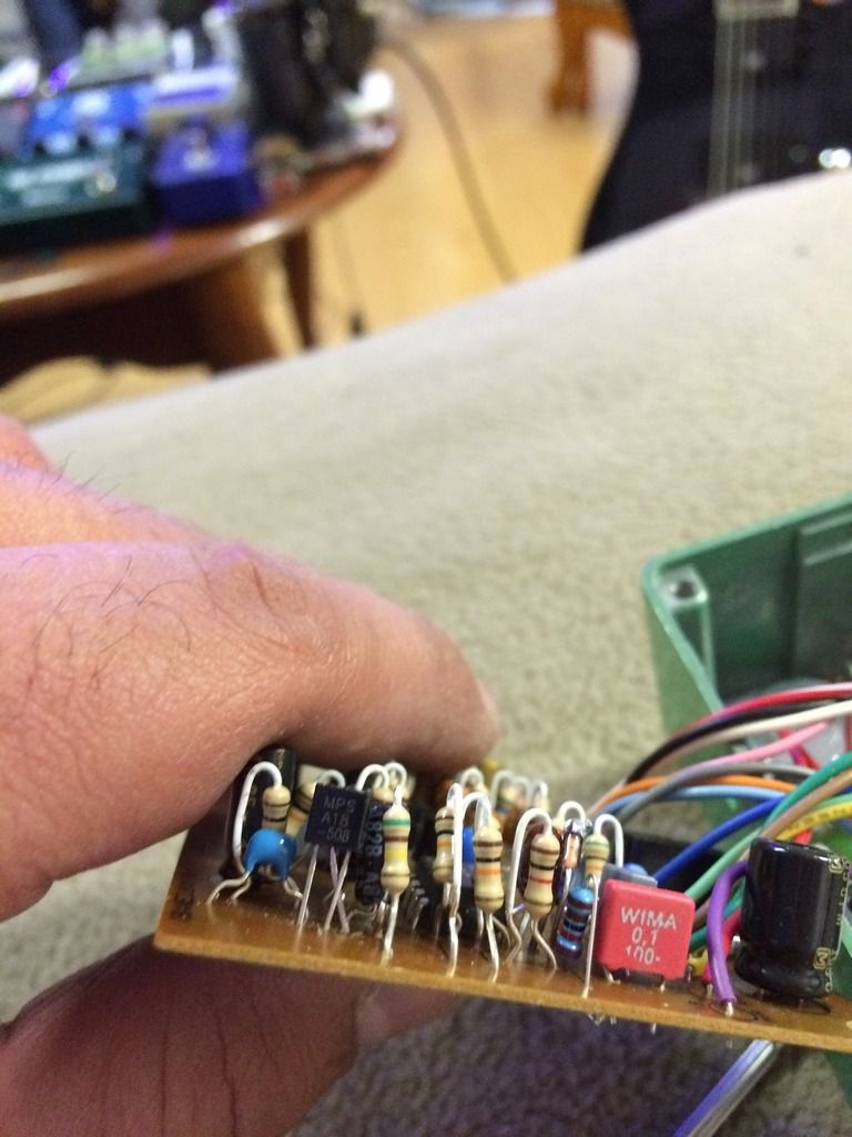
I changed the input cap to a mpsa 18 and from what I could see the pin outs arnt suppose to match but I'm not 100% positive this is correct if I'm having a issue. If anyone can help me verify. The other trannie is a 2Sc1815
#28
General Questions / Re: I violated my tube screamer and now need someone to save my ass
May 29, 2016, 04:25:22 PM
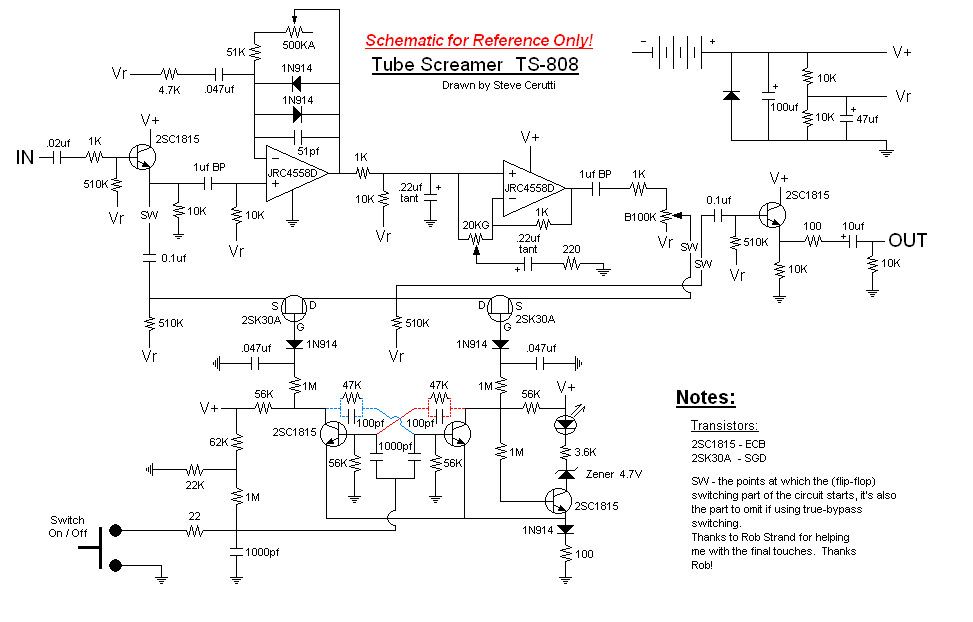
Amazing thanks so much guys. I actually wasn't going to use the stock values but just wanted to refer to them by there original part value That resistor I'm dropping to 2.2k and that 20nf cap is going to be a 100nf (cliche I know). Also planned on swapping out the input transistor for a ultra low noise mpsa18 and also swap the 51pf for a 51pf silver mica. I know it won't make much of a difference but it's more then tiny bit of noise it'll help with as well Bat41 /1n4148 asymmetrical clipping as well
Seriously thanks so much for the help and I'll post pics when I get home and le you know if everything goes well. I already did all of those mods except I have to change the 20nf cap to 100nf and also switch the 47 nf cap back because I switched the wrong one thinking that was the input cap
Seriously thanks so much for the help and I'll post pics when I get home and le you know if everything goes well. I already did all of those mods except I have to change the 20nf cap to 100nf and also switch the 47 nf cap back because I switched the wrong one thinking that was the input cap
Quote from: m-Kresol on May 29, 2016, 09:53:31 AM
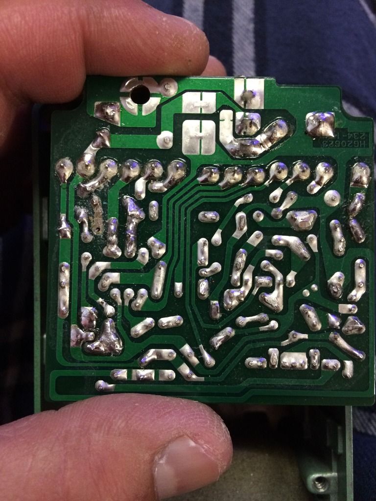
that pic helps a lot. It will be an easy fix, assuming you did not lift any other pads. do the following:
*) solder one leg of the 4k7 resistor to the Vr connection (the trace connecting to the pin marked '13')
*) solder one leg of the 47nF cap to the non-lifted pad it was attached to before (the one below the '10' pin)
*) bend the free legs of the resistor and cap towards each other (you can poke both trough the lifted pads and do this on the bottom of the board) and solder them together.
*) You're Done! The trace doesn't connect to anything else, so that's it.
I don't know what you did want to do by desoldering these parts, but this would be the 'back-to-stock-version' option.
Hope the instructions are clear. If not, I'll highlight the pads in question.
#29
General Questions / Re: I violated my tube screamer and now need someone to save my ass
May 29, 2016, 08:38:18 AM
Ok so your right it's the 47nf cap not the 20nf cap. So if anyone can think of a good place to connect it to as well it would help tons. I found a very useful page and here's a pic that will help tons. I just want to here from someone more experienced it's all good before I turn on my soldering iron again
Sorry for all the pictures
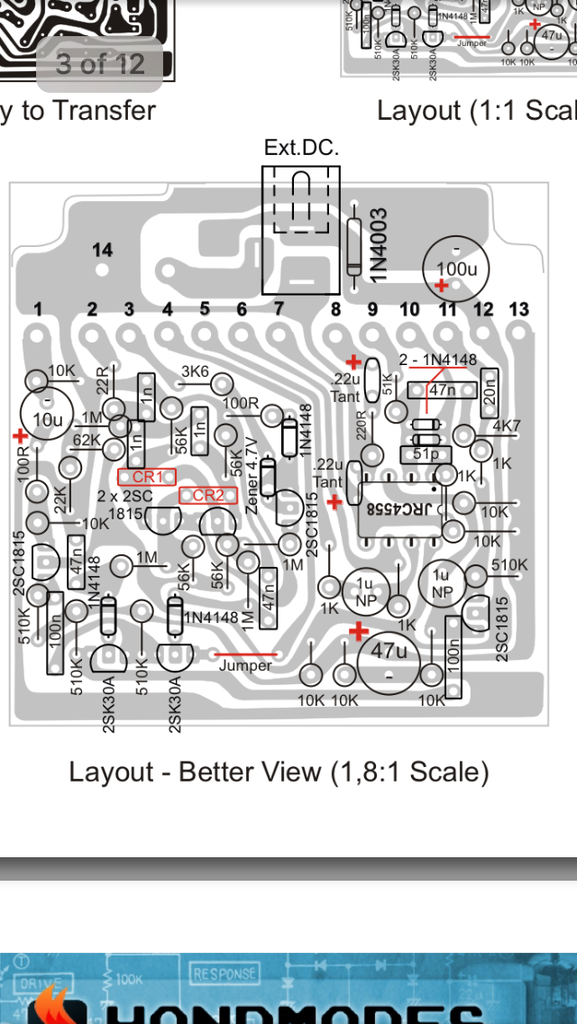
Sorry for all the pictures
#30
General Questions / Re: I violated my tube screamer and now need someone to save my ass
May 29, 2016, 06:37:52 AM