Yeah. The headers are soldered in. But there are no components hidden on the board below. All the pots, faders and switches are on the other side of that board.
I can take as many pics as you want
I can take as many pics as you want
This section allows you to view all posts made by this member. Note that you can only see posts made in areas you currently have access to.
Quote from: PMowdes on February 03, 2019, 02:15:21 PMI think sonic posted that schematic. It's kinda hard to read in parts.
Holy shit, I'd love to trace this. I have a set of documents which might be helpful, they include the schematics but the quality is too poor to make sense of for a reliable read.
Quote from: somnif on February 03, 2019, 12:04:23 PM
http://jbemond.free.fr/SDIY/EMS/EMS_Hifli.pdf
Circuit notes and schematic if you want to poke around. Scan quality sucks, unfortunately, but its something to work from.
More discussion: https://www.diystompboxes.com/smfforum/index.php?topic=94294.0
And more still: https://www.diystompboxes.com/smfforum/index.php?topic=73726.0
Quote from: Marshall Arts on February 03, 2019, 11:53:49 AM
Be very, very careful:
https://reverb.com/ca/item/1567718-original-ems-synthi-hi-fli-analog-guitar-synth-effects-ultra-rare-exc-vtg-cond
There is no "cannot fix it" at that price point.
Quote from: fair.child on February 03, 2019, 11:43:10 AM
Sure, I'll share when the project is complete. I'll say it's 70% complete. I want to do several designs (at least two approaches) on this. One is baseline copy and second is control improvement out of it.
Plan to sell the board as well. Now gotta think a sexy name!
Like 911, Lord Agile, Post Master, etc
Quote from: somnif on February 03, 2019, 11:39:19 AM
Are those all diodes there on the left?


Quote from: culturejam on January 04, 2019, 11:10:29 AMQuote from: bsoncini on January 04, 2019, 11:07:34 AM
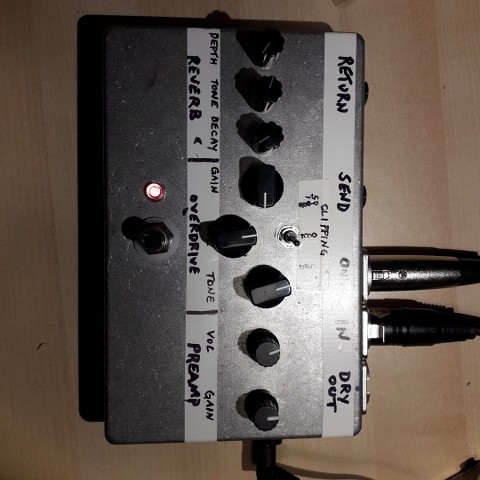
I built a pedal for a friend based on the $5 preamp that Frederik from parasites studio posted. Can't find it at this moment. The parts cost more than $5 though. The 1na217 in the preamp costs about 5 bucks and the drv123 which converts from unbalanced to balanced also costs about 5 bucks.
Anyway. I took the output from the preamp and sent it to a bluesbreaker. Into send return Jack's. Then into a belton based reverb. After that so many people liked them I've built 5 for other people.
Works really good and is silent. Also added a dry out but most people have wanted one so that the sound guy has no control over their effects. So they just use xlr in and out.
Thanks, I'll check it out!