
It's screenprinted from Pedal Parts Plus. The artwork file is available for download on the project page partway down. It's not cheap to order a one-off (enclosure + powdercoat + printing was close to $40 for mine, not including shipping) but if there's enough interest we could potentially order extras and Johnny could sell them for whatever price would make it worth his while. We're going to be getting at least 50 for the Alchemy run, so we could just add more enclosures to the order if we had people who were interested. These ones will be from Mammoth and will also be drilled as well.
- Welcome to madbeanpedals::forum.
This section allows you to view all posts made by this member. Note that you can only see posts made in areas you currently have access to.
#242
Build Reports / Re: Lab Series L5 preamp in a pedal
May 02, 2016, 04:11:58 AM
Not yet. I think Johnny from Alchemy Audio will be doing a run of them, and he was planning to do a video demo as part of it, but that'd still be a few months out at least.
#243
Build Reports / Re: Lab Series L5 preamp in a pedal
May 01, 2016, 07:04:41 PMQuote from: jimilee on May 01, 2016, 06:47:22 PM
That's beautiful, sounds like a serious, commitment, does it come with a prenup?
Got the attorney working on one right now...

#244
Build Reports / Lab Series L5 preamp in a pedal
May 01, 2016, 06:03:29 PM


This is the preamp section of a Lab Series L5 amp in pedal form. I've been chasing this sucker for years, having owned one of the amps since 2008 and wanting to do some sort of clone or adaptation long before I knew a thing about electronics. Finally got inspired this past fall to tackle it, and six months later, this is how it turned out. It feels good to have it done!
The last pic is the best I have for a gut shot - right before I did the wiring. I'll try to get a finalized wiring photo up in the next couple of days.
PCBs available here ($20 each for the next 2 weeks, use coupon "beanplate" - normally $24). Warning - not for the faint of heart... 12 pots, 4 switches, 80 resistors, 50 caps and 12 ICs!
#245
General Questions / Re: Can someone help me understand a few parts of the Boss Dimension C circuit?
April 12, 2016, 03:50:05 AMQuote from: alanp on April 11, 2016, 09:26:11 PM
Oooo. That's caught my eye
You're not using the normal Eagle "pinhead.lbr" header pins?
Nope, didn't even know about that one! Just a bunch of individual square pads. This method does have the advantage that you can put the pins anywhere on the schematic that you want - the pinhead library looks like it wants you to run the wires to it which could get a bit messy.
Quote from: solderfumes
And I do! That looks very cool. I'll pass this time, but thanks for the offer. Maybe if I want to build another one though! Looks like you've gone with three mode switches, much like the original; I'm planning to go with depth and rate knobs. I've also identified a few mods that work better for me, such as decreasing the gain on the compressor and increasing it on the expander to avoid BBD distortion, and I'll include spots for the capacitors that I talked about previously. I'm also going to put in a CV input, to go with a tap tempo unit I built based around the TAPLFO chip. Mostly, though, I'm looking forward to making my own layout, because fitting all the components onto the board is like crack for an old Tetris addict like me.
Wow, you're all in! That's going to be fun. I'm tossing around the idea of doing another "deluxe" version with stereo in/out and a few other enhancements, but I'm so drained from working this layout every day for the past month that it might be awhile before I have the mental energy to tackle it.
Let me know if you come up with any new mods or tweaks you want to share and I can include them in the docs!
#246
General Questions / Re: Can someone help me understand a few parts of the Boss Dimension C circuit?
April 11, 2016, 06:00:08 PM
Not sure what your plan is for getting it off the breadboard and into a box, but if you can wait another 6-8 weeks I'll have a DC-2 DIY project ready to go. Just sent off for the prototypes this past Friday.
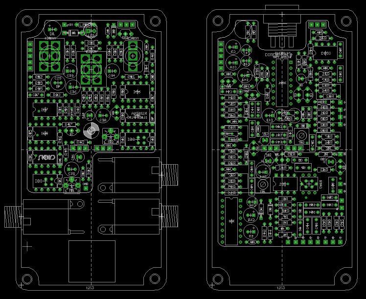
The PCBs are double-decker: signal & switching on the top PCB, clock & LFO on the bottom (with holes for top trimmer adjustment). 125B enclosure, all 1/4w flat-mounted resistors and standard box caps. Supports either stock buffered bypass (signal goes through pre-emphasis and de-emphasis filters) or minimally-buffered bypass (signal only goes through the first op-amp stage and is split to each output).
I don't mean to drop in and advertise... just one of those "if it were me I'd wanna know" situations
#247
Open Discussion / DC-2 Dimension C clone - soliciting opinions on how to design the bypass
March 20, 2016, 01:40:18 PM
So, I decided to tackle the Dimension C (!) and am about halfway through the design process for a project that I will release to the community in a couple months. It's going to be in a 125-B and no SMD. It's been a fun challenge and I've got a solid plan to make it all fit..
Now I'm getting to the point where I have to decide which bypass scheme to use. I was originally just going to use the Boss bypass—the DC-2 uses op-amps for the buffers, so as long as you use good-quality op-amps, the bypass should sound great. However, I just found out that the original Boss bypass doesn't work well with the mechanical momentary switches I was planning on designing around - it's made for a tactile switch that has much less bounce, and the circuit can be unreliable when using something other than a tactile. So that's a no-go.
This pedal is a mono->stereo splitter, so traditional true bypass isn't in the cards. It's got to at least pass through the first op-amp buffer stage to cleanly split the signal. I've seen others do senseless things in the name of true bypass (IIRC the Fromel Seraph would actually cut out the 2nd channel when in bypass mode... what?) and I want to make sure this is done right. Just looking for some opinions and feedback on what is the "rightest"
Original schematic here. The two circuit options, as I see it:
1) Preserve the original bypass path, meaning it goes through the input buffer, then pre-emphasis, de-emphasis, and out. Requires the equivalent of three SPST switches, plus LED.
2) Hard-wire the circuit "on" (omit & jumper Q1, Q11, Q12). Split the signal immediately after the input buffer. One pole of the switch grounds the circuit input from that point, and two poles switch the outputs, each going through an output cap. Still requires the equivalent of three switch poles not including LED, but this time they have to be double-throw.
Then there's also the actual technology of the bypass:
1) Mictester's latching relay, using a latching SPST switch and using two DPDT relays in parallel. One of the four relay switches will be unused. The relays are $3 each, but the other parts are pennies.
2) Optical bypass (H11F1/Optotron method), but with a 3PDT stomp switch instead of the usual DPDT. The one downside here is that the post-buffer input would not be grounded in bypass, just blocked by the optoFET, but that's probably fine.
3) 4PDT switch. (I really, really, really don't want to do this because of the inconvenience of sourcing them and the potential for hardware failure, but it's an option.)
I think either circuit scheme will work with any of the three bypass methods, so any combination of the above is an option. Whichever method I decide on will have to be built into the circuit and will be pretty much required, so that's why I'm trying to get some feedback before going full steam ahead on one specific method. What do you guys think? If you were building it, what would be your preference and why?
#248
Build Reports / Re: Switch Monkey (FS3X)
February 26, 2016, 11:57:57 AM
Very nice etching job! And clever way for Digitech to get a third function out of a stereo jack.
#249
Build Reports / Re: A couple of Aion Electronics builds
February 26, 2016, 11:53:34 AM
WOW! I didn't see these the first time around, but great work, those are fantastic!
#250
Build Reports / Re: 2011 Current Lover finished... finally!
February 17, 2016, 10:42:12 AM
Small Bear. The short ones are all I use anymore! Here is a SPDT on-on:
http://smallbear-electronics.mybigcommerce.com/spdt-on-on-0218b/
Steve also has them in on-off-on and DPDT, which covers 95% of my needs.
BLMS has an even wider variety (including 3PDT toggles and PCB pin mount versions of all of them) but they are a cheaper off-brand. SBE carries Taiway which is top notch.
#251
General Questions / Re: Pig Butt - Diode Socketing?
February 14, 2016, 07:36:53 AM
Yep, they are clipping diodes - but honestly you probably won't get much out of changing them since the signal is so mangled in this circuit. The 3x diodes in each direction is about the same forward voltage as one LED (~1.8-2V).
#252
Build Reports / 2011 Current Lover finished... finally!
February 13, 2016, 01:30:49 PM

Does this qualify as vintage now?
I originally purchased the board in 2011 or 2012, and populated pretty much right away, but then the hold-up was the enclosure. I had to design it first, so I traced the Electric Mistress logo in vector. Then Pedal Parts Plus temporarily stopped doing one-off printing jobs so my next option was to etch it - but for some reason my toner transfers weren't sticking to the particular alloy of the 125Bs I was using, or something. I don't know. What a pain. Then I got fed up with it and left it in a box for a couple years.
PPP started doing one-offs again, so I ordered one on their chrome powdercoat (which is really nice, by the way - a good alternative to polished aluminum), and was finally able to finish it up. It fired up the first time, which is awesome considering that I soldered it almost four years ago!
One word of caution, the UV printing over the chrome powdercoat is not super durable. I scratched some off when I was tightening the nuts. Fortunately it's mostly covered up, and it'll be easy to touch up the visible parts, but still, I was a bit disappointed. But I suppose that it'll just make it look road-worn vintage faster than normal
#253
Open Discussion / Re: GCFX New Website and other great news!
January 19, 2016, 10:28:11 AM
Love it! You made the right choice with WP + WooCommerce.
#254
Open Discussion / Re: Mouser Xicon resistor price bump
April 20, 2015, 10:37:29 AMQuote from: dadler on April 20, 2015, 09:25:19 AM
Xicons @ Mouser seem to have doubled in price again, to $10/200. Geez I thought $5/200 was expensive.
http://www.mouser.com/ProductDetail/Xicon/270-10K-RC/?qs=sGAEpiMZZMu61qfTUdNhG%2fNICg4NOtz5D3ChGIwXeqI%3d
Not all of them are that much, but wow, for such a common value that's a bummer. I checked yesterday and it seemed on a casual glance like it was mostly your non-standard high-precision values like 12.1k. I guess not.
#255
Open Discussion / Re: L78l05... Why...
April 14, 2015, 07:43:34 PM
Opposite of the full-size 7805, yeah.
I'll tell you why I don't trust them: the Gaussmarkov EAGLE libraries had the 78L05 set to the same pinout as the 7805, and it caused me a great deal of troubleshooting grief because I didn't consider that the library itself could have a mistake.
I trust them now... but only in my own layouts
I'll tell you why I don't trust them: the Gaussmarkov EAGLE libraries had the 78L05 set to the same pinout as the 7805, and it caused me a great deal of troubleshooting grief because I didn't consider that the library itself could have a mistake.
I trust them now... but only in my own layouts