
Hoping to adapt both these pedals for bass by adding a clean blend which includes a buffer and doesn't like inverted phase. I have no idea how to determine if these invert... can anyone here help?
- Welcome to madbeanpedals::forum.
This section allows you to view all posts made by this member. Note that you can only see posts made in areas you currently have access to.
#1
Open Discussion / Do these effects invert phase? Cornish NG-2 & Drolo Giant Hogweed
March 09, 2021, 12:43:15 PM #2
Open Discussion / Considering giving up on the DIY pedal hobby...
November 04, 2018, 09:25:56 AM
This has been on my mind for a while now. I don't mean this to be dramatic or anything. I just figured I'd share my thoughts after doing this for about 7 to 8 years or so building effects for myself and occasionally for others.
I started this for two reasons. First was for fun. Because it's fun and rewarding to build something yourself. I also did it figuring I'd save some money and could possibly make some if I developed enough skill. This second reason quickly travelled itself to be impossible. You definitely don't save much money building for yourself, and if you factor in the cost of your time and the requirements for space, part inventory, etc. it quickly becomes clear it's not going to be worth it for the cash savings. And I could share stories about the sad state of trying to sell these things but I'm sure you've all heard them before and likely experience them first hand as well.
So, more recently, I've grown up a bit, got engaged, moved further in my career, got a few dogs (3), working to finish my dissertation, trying to keep up with health and fitness, etc. And I've found there's little "free" time left after all of the necessities. I'd like to spend that free time doing something I enjoy but I feel and I do enjoy building, but my time spent on building means a sacrifice of time playing guitar and learning to be a better musician. But the backlog of partial builds keeps calling me back... so I am giving serious thought to calling it quits... after I clear out a few large projects that are unobtainable pedals (PLL, some interesting fuzzes, etc.). I'm sure I'll miss it but with the low cost of gear and the huge range of stuff out there, I'm thinking I'll come out financially ahead and with more available time for other pursuits if I give it up.
Anyway, that's where I'm at. Thanks for letting me share madbeaners.
#3
General Questions / DeadEndFX Build Docs?
October 20, 2018, 04:22:14 PM
I have several DeadEndFX PCBs that just arrived after moving and wanted to pull together build docs. Can anyone send me the build docs for...
-- Fuzzimile
-- Laika Fuzz
-- PLL One
-- Skyripper
-- Fuzzimile
-- Laika Fuzz
-- PLL One
-- Skyripper
#4
Tech Help - Projects Page / Road Rage w/ 4.5V output
December 31, 2017, 06:34:48 AM
Is there a way to modify the road rage to output 9v and 4.5v? Trying to rehouse a dano pedal and would like to use the road rage to provide the 9v power and a 4.5v power source to replace the switching board...

#5
Tech Help - Projects Page / Clipper Ship Question - SOLVED
December 27, 2017, 08:07:25 AM
I put together a clipper ship using a PCB kindly gifted to me by a madbeaner over the holiday break and, unfortunately, only had a moment to test it and it didn't go so well, so I have some debugging to do, however, I am curious of something for anyone familiar with the circuit...
My build has uses...
R3 - socketed (7.5k was used to test)
Q1 -
Q2/Q3 - 2N5457
D1 - 1N5817
D2 - omitted
D3/D4 - on a switch with diodes ranging from 0.27v to 0.75v forward voltage
I don't have many NPN Ge transistors, unfortunately, but I was testing it with a spam can GE 2N1101 transistor with hFe (on my Peak meter) of 45 with a leakage of about 0.08uA or mA (whatever the standard output is for that... this is from memory). Bypass was good but the with the pedal on, I get decent volume when engaged that quickly drops off (fraction of a second basically) and the sound is then well below unity gain. I hear distortion so it's clipping, but for some reason, even with max volume, I'm getting less than unity gain. I'll poke around and check values but was curious if what I was finding could be caused by the low hFe on the transistor or something similar.
Thanks for any help! Will update and provide photos once I get a chance to go over it and verify everything again...
Build doc used provided below for reference...
#6
Tech Help - Projects Page / Aion Refractor Issues - SOLVED
December 17, 2017, 04:56:33 PM
Another swing and a miss. I built this Klon clone (hopefully my last) and it's gated and has issues in bypass as well as on so my issue is likely around IC1, I think but not sure. Anyway, I already verified all components and polarities although I could have made a mistake somewhere. Voltages are off. Even swapped IC's to no avail. Will pull the board and reflow if I can't get any leads on the issue... My TL072 voltages look way off.
Substitutions:
C6 - 390n -- used a 330n and 56n in parallel
R12 - 422k -- used 470k and 3.9M in parallel
POWER: 9.5V
Diode voltages (cathode/anode)
Zener Voltage: 0 / 9.5V
D3 (1n4002): 13.59V / 9.5V
D4 (1n4002): 17.31V / 13.59V
IC 1: TLO72CP
Pin 1, 1.334
Pin 2, 1.334
Pin 3, 0.962
Pin 4, 0
Pin 5, 0.665
Pin 6, 1.083
Pin 7, 8.77
Pin 8, 9.50
IC 2: TLO72CP
Pin 1, -2.730
Pin 2, 0.472
Pin 3, 0.472
Pin 4, -9.14
Pin 5, 0.473
Pin 6, 0.471
Pin 7, 3.695
Pin 8, 17.31
IC 3: TC1044
Pin 1, 9.5
Pin 2, 4.918
Pin 3, 0
Pin 4, -4.424
Pin 5, -9.14
Pin 6, 4.651
Pin 7, 6.184
Pin 8, 9.5
#7
Tech Help - Projects Page / Cascadia Issues
December 08, 2017, 01:08:48 PM
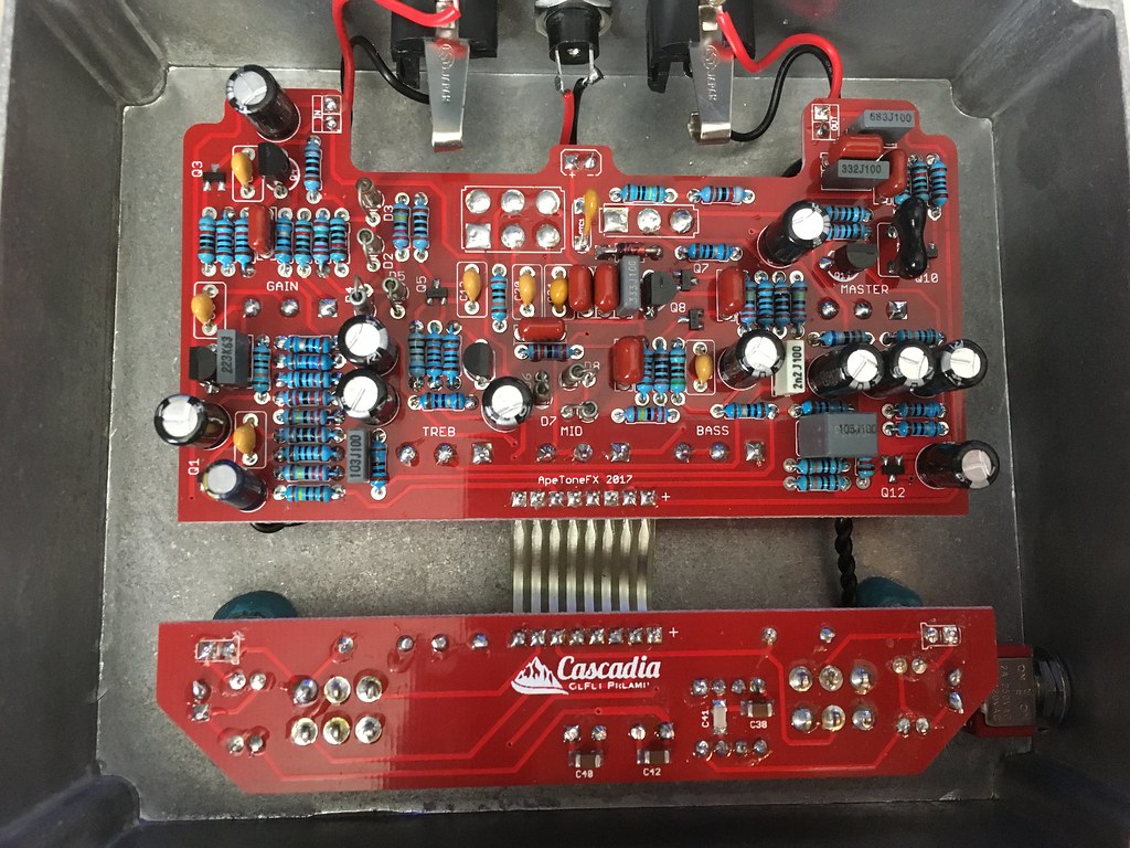
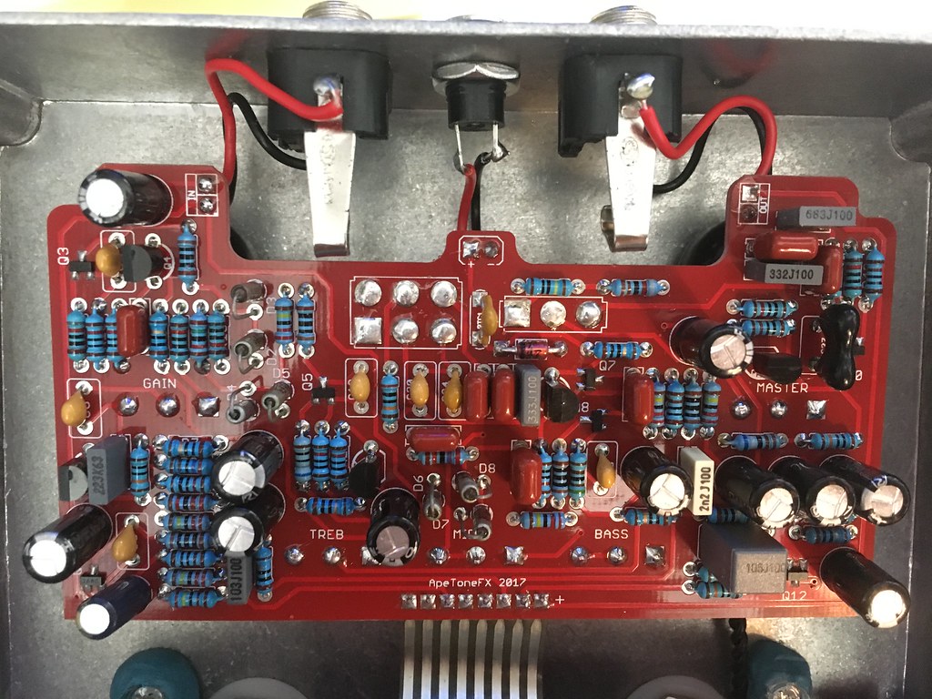
So I got this built up and it was relatively straightforward but I'm having a few issues. The diodes are all smallbear 1n695's as recommended and no substitutions except an added switch to parallel a resistor with R5 to make the second switch boost more based on some comments in the group buy thread. The center setting eliminates the extra resistor and all the issues occur regardless of the setting.
1. The DPDT on-on "Bright" switch does not work in the "right" position. It occasionally has a very faint flubby sound but it quickly fades and isn't really repeatable. Checked continuity on this switch and it appears to be working correctly.
2. The treble control appears to work in revers and has limited range. It seems like it cuts treble when turned clockwise which seems wrong based on the way the other two controls work.
3. The overall sound of the pedal is very flubby and somewhat gated. Definitely not as described in many build reports.
So that said, I am guessing I made an error. Can anyone help diagnose it? Without IC's other than the charge pump, I'm not sure where voltages would be helpful. The charge pump IC has the following voltages
Power Jack: 9.35V
IC1:
1 - 1.332
2 - 4.116
3 - 0.002
4 - (-)4.925
5 - 0
6 - 2.522
7 - 1.441
8 - 9.29
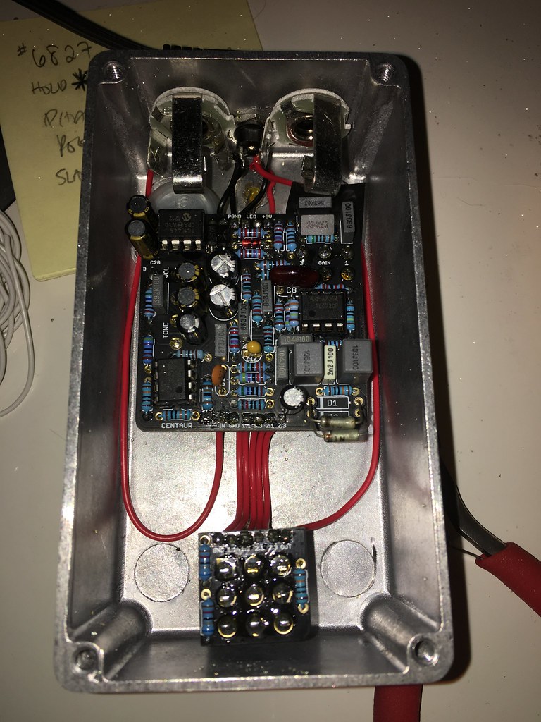
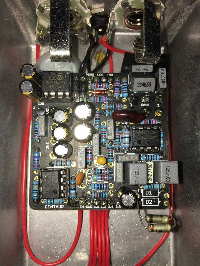
Pics of it in the box... I'll pull it out if I need to, of course but hoping for a diagnosis without that. Guessing it's a bad solder joint since gordo has similar issues...http://www.madbeanpedals.com/forum/index.php?topic=26726.15
1. The DPDT on-on "Bright" switch does not work in the "right" position. It occasionally has a very faint flubby sound but it quickly fades and isn't really repeatable. Checked continuity on this switch and it appears to be working correctly.
2. The treble control appears to work in revers and has limited range. It seems like it cuts treble when turned clockwise which seems wrong based on the way the other two controls work.
3. The overall sound of the pedal is very flubby and somewhat gated. Definitely not as described in many build reports.
So that said, I am guessing I made an error. Can anyone help diagnose it? Without IC's other than the charge pump, I'm not sure where voltages would be helpful. The charge pump IC has the following voltages
Power Jack: 9.35V
IC1:
1 - 1.332
2 - 4.116
3 - 0.002
4 - (-)4.925
5 - 0
6 - 2.522
7 - 1.441
8 - 9.29
Pics of it in the box... I'll pull it out if I need to, of course but hoping for a diagnosis without that. Guessing it's a bad solder joint since gordo has similar issues...http://www.madbeanpedals.com/forum/index.php?topic=26726.15
#8
General Questions / 1n4148 - any difference between new and old?
November 25, 2017, 04:07:13 PM
I got a vintage style PCB for a Grey DOD 250 and all vintage correct parts are on there already except the diodes. I have some Tayda 1n4148's here and can slap them in but was curious if there is any difference between current production 1n4148's and those available in the 70's. Anyone know? If there's some mojo to be had there, anyone have a couple 1n4148's they'd like to part with for a reasonable price?
#9
Open Discussion / NO/NC Momentary bypass - where and what to get?
August 01, 2017, 03:28:27 PM
Who makes the best true bypass that will work with a momentary NO or NC switch?
I saw this... https://www.mammothelectronics.com/products/click-less-true-bypass-relay-module-kit
And it got me wondering who all makes these things and which are the best in your opinion? I feel like $20 is a bit steep but I don't have the relay or IC that I can see in this photo on hand so I'd be sourcing quite a bit to build something similar. Anyone use these switches a lot? If so, what do you use and why? I have a build I'd like to use it for in the near future so I can use something other than a normal stomp switch.
Thanks!
#10
Build Reports / Mod-Ring -- Second Version
April 17, 2017, 07:48:53 AM
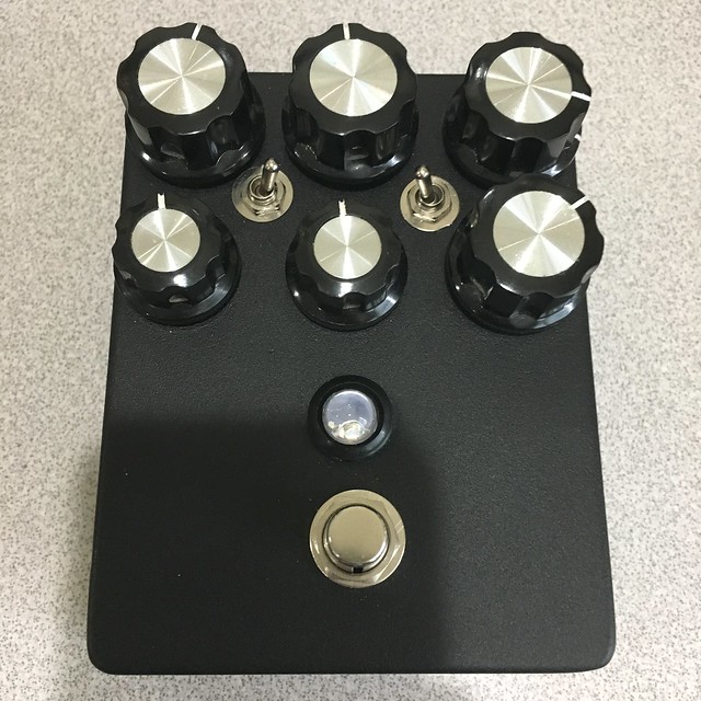
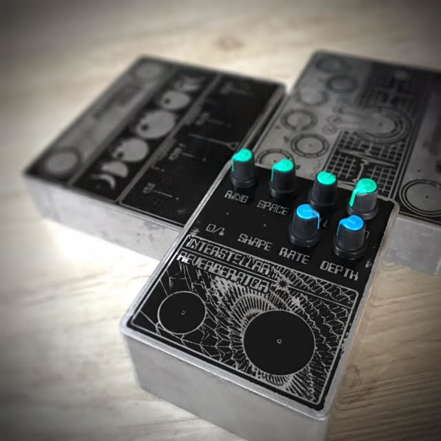
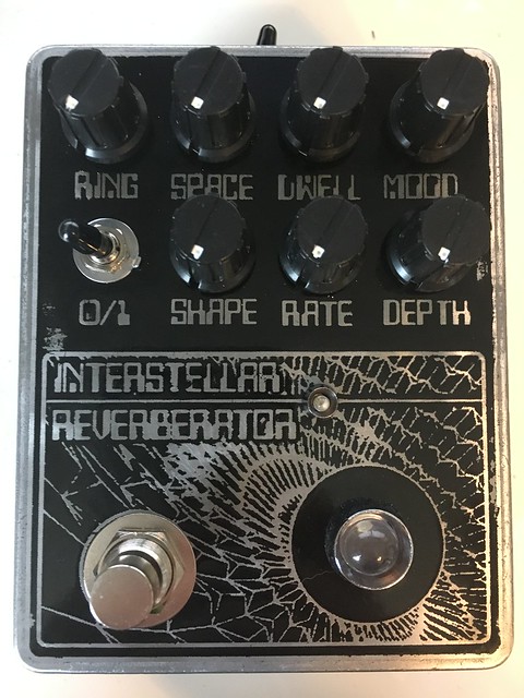
So, I built a mood ring a while back and Boba7's build with modulation was so cool I had to add it to mine. So I built this guy up... Standard mood ring controls (mood, space, dwell, ring, dry-kill) with added modulation on vero with rate and depth controls (sine wave shape hard-wired) and on/off toggle for the modulation. It turned out really nicely, I thought, although I drilled the LED about 1/16th off center and it drives me kind of crazy...
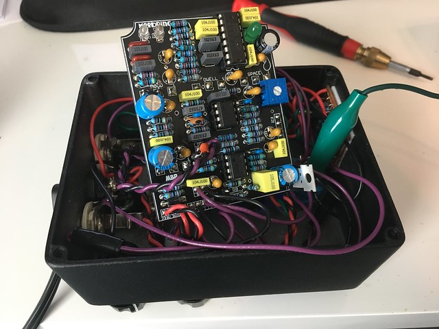
Gut shot from when I was debugging a wrong resistor. It's got a lot of wire in there and the mod board is stuck to the bottom edge of the enclosure in the photo. I probably could have built it cleaner but I intended for this to be the learning phase and I learned quite a bit but the biggest takeaway is that Boba7 has a great ear and suggested some excellent mods.
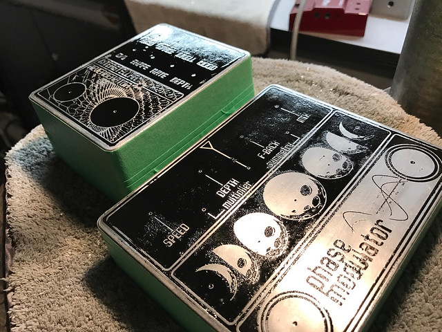
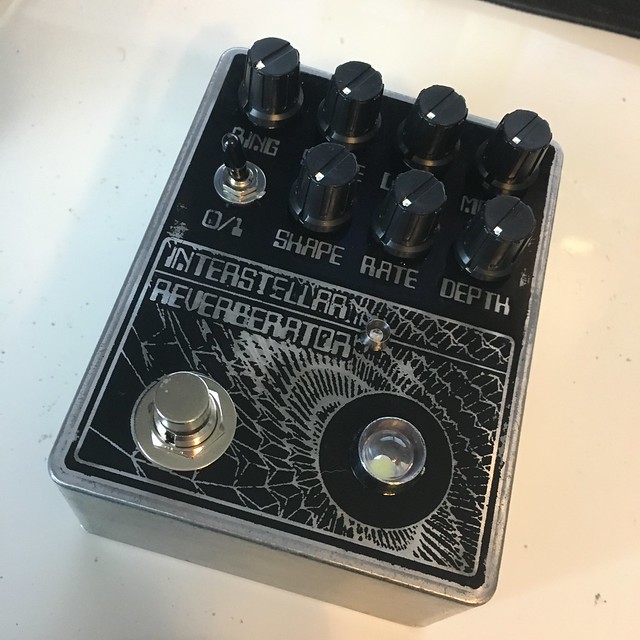
This guy lived on my board for the past few months and is awesome. I decided it was definitely a keeper (rare these days for me), so I begged dminner to etch me a nice enclosure. I have plans for one more reverb but that's going to be a true spring verb in a head enclosure so this will be the one and only reverb on the pedal board for me. Dan obliged and etched a really nice enclosure (I wish I could create something even half this cool looking on my own).
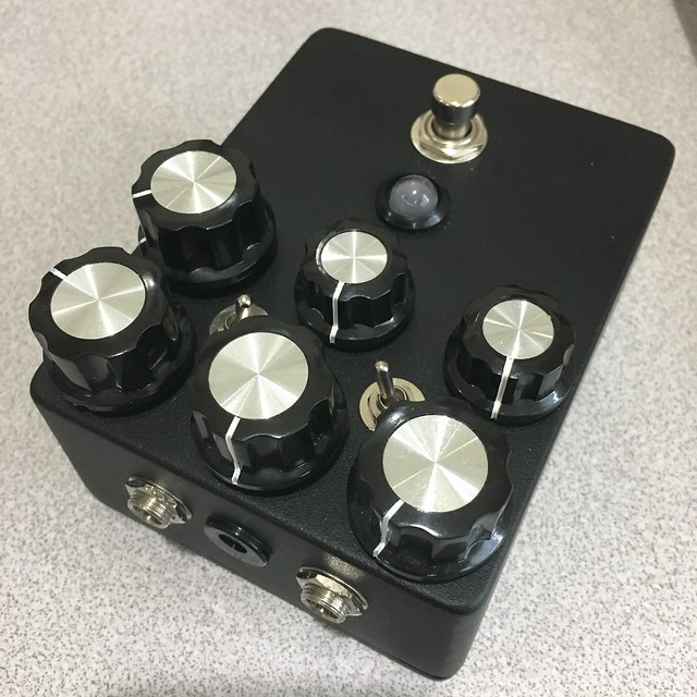
In the back here...
In the front here...
Finally, the past 2 weekends were partially spent on this project and partially on another. Finally, this weekend, I was able to get this beast wired up and it fired up first try (although I did some trouble shooting while assembling so that's not totally accurate). It's got the following boards in there...
1. Grind Customs Lumen Optical Bypass
2. Grind Customs PLFO Modulation Board
-- Wired to DPDT switch to turn on/off modulation LED and make/break connection to space pot
3. Vero daughter board for PLFO for rate LED (thanks Boba7 for the notes!)
4. Madbean Mood Ring
-- Increased feedback and brightness mods courtesy for Boba7 again
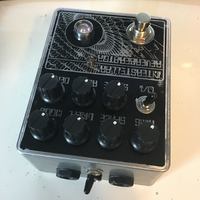
This one is still a bit of a mess inside but pretty darn clean and LOTS of controls. I absolutely love it. I wired the dry kill switch on the top edge which was easy since it's in a 1590BBT with lots of depth. Top jacks like almost all my builds. I prefer that for simplicity and space savings. Modulation board has a pot for rate and depth of mod, another pot for shape that goes from sine/triangle wave on the left to square wave on the right and an on/off toggle. 10mm white LED for on/off, 3mm blue LED for mod.
Cleaner guts than before but still a bit of a mess due to the multiple boards and limited space...
Wow... quite the post. Very cool project and very empowering. Hoping to keep this momentum up in my next personal build. I feel like I haven't built much for myself lately but between my 5e3 and this reverb the past few weeks have been very rewarding.
Now I probably need to sell the black one off since it's been usurped...
Thanks for all the hard work that allowed me to build this Brian, Rej, Dan and Boba7!
Gut shot from when I was debugging a wrong resistor. It's got a lot of wire in there and the mod board is stuck to the bottom edge of the enclosure in the photo. I probably could have built it cleaner but I intended for this to be the learning phase and I learned quite a bit but the biggest takeaway is that Boba7 has a great ear and suggested some excellent mods.
This guy lived on my board for the past few months and is awesome. I decided it was definitely a keeper (rare these days for me), so I begged dminner to etch me a nice enclosure. I have plans for one more reverb but that's going to be a true spring verb in a head enclosure so this will be the one and only reverb on the pedal board for me. Dan obliged and etched a really nice enclosure (I wish I could create something even half this cool looking on my own).
In the back here...
In the front here...
Finally, the past 2 weekends were partially spent on this project and partially on another. Finally, this weekend, I was able to get this beast wired up and it fired up first try (although I did some trouble shooting while assembling so that's not totally accurate). It's got the following boards in there...
1. Grind Customs Lumen Optical Bypass
2. Grind Customs PLFO Modulation Board
-- Wired to DPDT switch to turn on/off modulation LED and make/break connection to space pot
3. Vero daughter board for PLFO for rate LED (thanks Boba7 for the notes!)
4. Madbean Mood Ring
-- Increased feedback and brightness mods courtesy for Boba7 again
This one is still a bit of a mess inside but pretty darn clean and LOTS of controls. I absolutely love it. I wired the dry kill switch on the top edge which was easy since it's in a 1590BBT with lots of depth. Top jacks like almost all my builds. I prefer that for simplicity and space savings. Modulation board has a pot for rate and depth of mod, another pot for shape that goes from sine/triangle wave on the left to square wave on the right and an on/off toggle. 10mm white LED for on/off, 3mm blue LED for mod.
Cleaner guts than before but still a bit of a mess due to the multiple boards and limited space...
Wow... quite the post. Very cool project and very empowering. Hoping to keep this momentum up in my next personal build. I feel like I haven't built much for myself lately but between my 5e3 and this reverb the past few weeks have been very rewarding.
Now I probably need to sell the black one off since it's been usurped...
Thanks for all the hard work that allowed me to build this Brian, Rej, Dan and Boba7!
#11
Build Reports / Silicon Fuzzrite
April 03, 2017, 08:51:39 AM
Had someone ask for a custom fuzzrite similar to one I built a while back using some vintage components and it came out great so I figured I'd post it. I followed the IVIark mojo axial layout. Thankfully, I populated a second vero board while building this and plan to put one together for myself using that at some point. Probably won't use the vintage solid core wire as I'd prefer a smaller footprint but other than that I'll build it the same. It's definitely a keeper and I highly recommend it to any fuzz guys out there.
When I build the next one up for myself, I'll definitely lay it out so I can display the board better.
When I build the next one up for myself, I'll definitely lay it out so I can display the board better.
#12
Build Reports / My Klone (Madbean Sunking)
March 13, 2017, 04:25:50 PM
I've had this PCB for years and finally got around to build it. Not too fun for me building in tight quarters (I prefer larger layouts and enclosures) but I really dig how it turned out and it sounds great. I played around with diodes too and settled on the 1n695's that I have with 0.35v forward voltage. Sounds great. BAT43 was good too but they had a flubby bass that I couldn't quite bond with. Oh, and this was my first chance to work with a smallbear bare box (isnt that what they're called?). I have to say though, I'm pretty annoyed as this was predrilled and the holes are not symmetric... the damn tone is about an eighth of an inch off center and pretty obvious and it really gets to my OCD... ah well, sounds good.
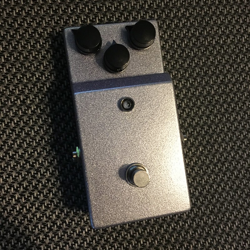
I have to say the punch and upper mid presence of the Klon circuit is why I think so many like it. That and the compression it seems to add. It makes for a very clear and cutting sound that really shines for me. And, despite the lack of top jacks, this one will likely make the board... that is until I build another one with the Aion board that I have laying around that does have top jacks
I have to say the punch and upper mid presence of the Klon circuit is why I think so many like it. That and the compression it seems to add. It makes for a very clear and cutting sound that really shines for me. And, despite the lack of top jacks, this one will likely make the board... that is until I build another one with the Aion board that I have laying around that does have top jacks
#13
Tech Help - Projects Page / Bad CA3080?
February 19, 2017, 02:35:19 PM
Just curious, where is everyone sourcing these? I got (5) from Amazon and my Kraken is not working using it. It could be something else, but I'm suspecting this chip. All I get is clicks that change with the various control and if I blast the volume on my amp I'm getting highly distorted, very quiet signal coming through.
https://www.amazon.com/pcs-CA3080-incl-8-pin-socket/dp/B01CM2TH7U/ref=sr_1_1?ie=UTF8&qid=1487543554&sr=8-1&keywords=ca3080
Please let me know if anyone has tried these and verified they are good. I've tried two with the same result (so it could be something else), but I plan to try a known "good" chip before going through too much trouble poking around on the board.
#14
Build Reports / GC Catch 22
January 16, 2017, 12:36:57 PM
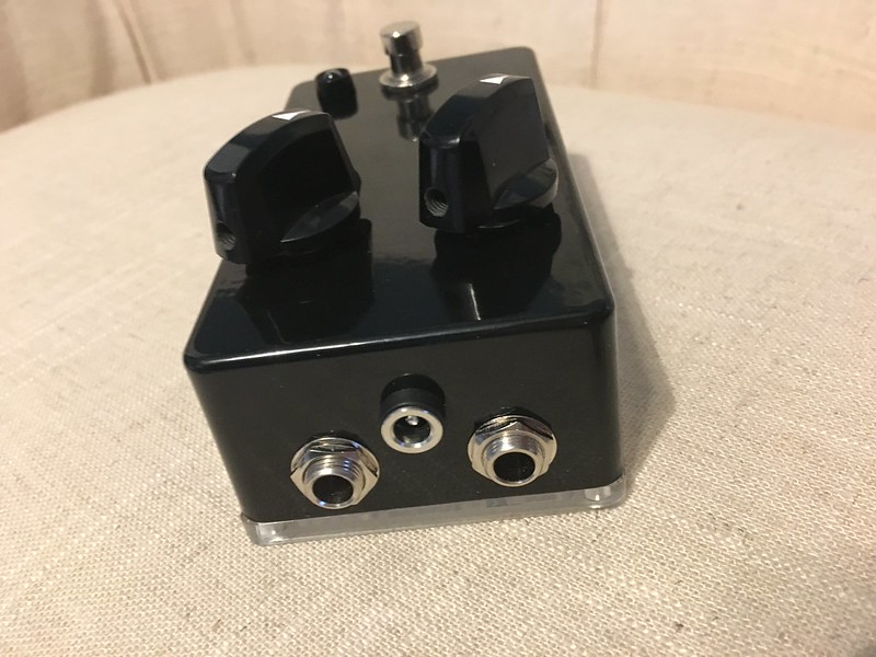
One final one from this weekend. This one is actually really cool. It's based on the Timmy and while I never bonded with that one, this one seems to be a pretty nice OD. I'm looking forward to playing it alongside the SS2 (duplex drive) I built to see which I prefer.
I really liked this white enclosure from Tayda and plan to pick more up as they look pretty nice.
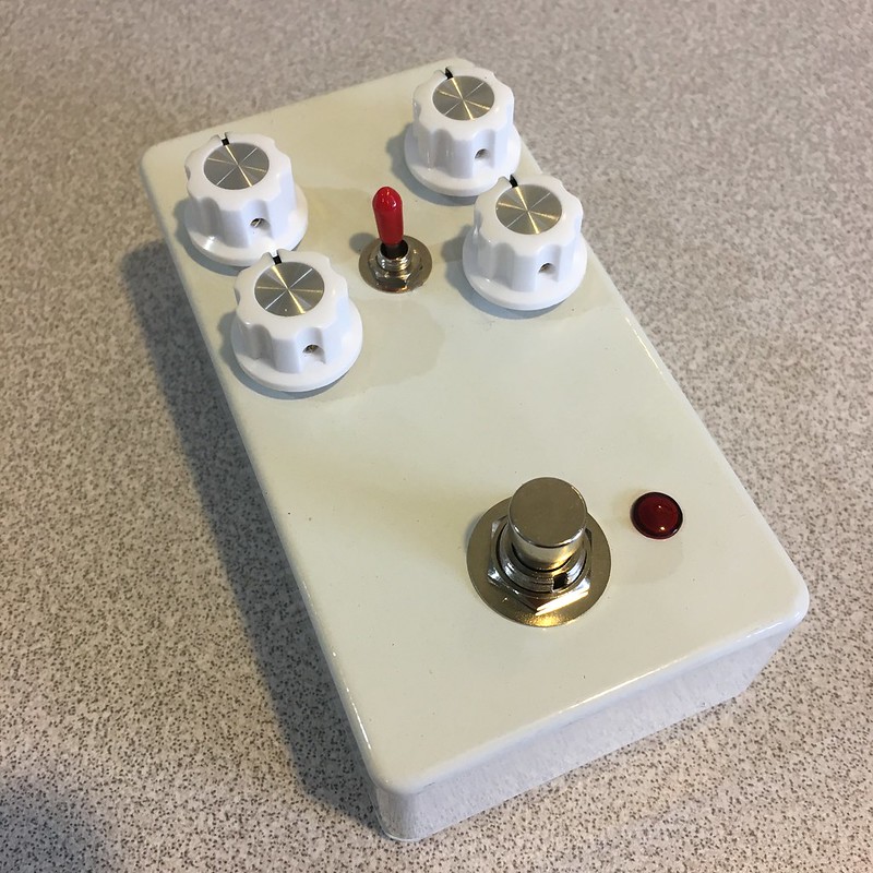
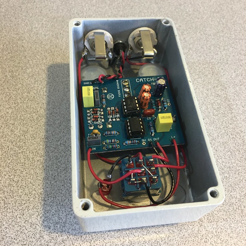
I really liked this white enclosure from Tayda and plan to pick more up as they look pretty nice.
#15
Build Reports / Pork Barrel #2 | Hot Cake
January 16, 2017, 07:48:33 AM
Another couple finished up over the weekend. A hot cake clone and a second pork barrel with blue LEDs this time. The chorus uses MN3007 and 3101 chips and a 3PRR to get 12v to the board. It also has the clear bottom plate and a 10mm LED inside that pulses with the rate control making the bottom plate light up. Kinda cool. After playing with both 9 and 12v there is little difference to my ears (same comment in the build doc). Maybe a bit more headroom and clarity at 12v but it could just be placebo effect.
CE-2 (didn't take a good outside shot... or inside shot actually... my iPhone camera skills suck)
Hot Cake w/ some slight mods
Not much to say. They both sound great. I'll be keeping this chorus and likely sending the other to my friends father who is a guitarist. He inspired me to start playing which is great and I still remember about 5 years ago when I was building effects having a conversation with him about the CE-2 and how he really liked it. I told him I'd build him one then life happened, several moves and no time to build. I'm glad I finally got this one completed. I'll send him the one I put in the BOTY contest except I will unbox it and spray the black box with some silver and/or black hammertone or something to spruce it up. I don't mind stuff for me being plain but when it's for others, I feel guilty
#16
Build Reports / Lab Series L5 Preamp (Aion)
January 16, 2017, 07:27:49 AM
2017 is rolling along smoothly. Got this guy finished up and calibrated this weekend. Very cool and versatile pedal with lots of tweakability in the EQ of each channel. Channel 1 is definitely the lower gain of the two but can get a little dynamic grit going. I'm still wrapping my head around the EQ on Channel 2 (particularly the multifilter) and the limiter. This is a really cool project and by far the most professional looking build I have ever done. Not by my doing, of course, but it remains true nonetheless.
Thanks Aion for putting together this excellent board, enclosure, label and build doc!
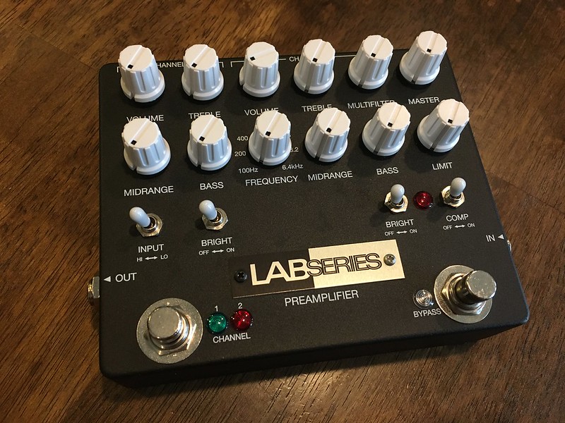
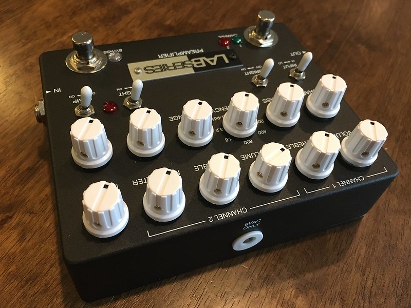
The only possible change I may make is replacing one of the op amps. When I built it up and calibrated it I only had one LM741 so I used a TL071 (I think) in place of one of them. I have more 741's now so I may swap that out to get it exact with the build doc. It seems to function fine with the TL071 though.
Anyway, a cool project and a bit more expensive due to all the special parts, enclosure, power supply, etc. but it turned out awesome.
Thanks Aion for putting together this excellent board, enclosure, label and build doc!
The only possible change I may make is replacing one of the op amps. When I built it up and calibrated it I only had one LM741 so I used a TL071 (I think) in place of one of them. I have more 741's now so I may swap that out to get it exact with the build doc. It seems to function fine with the TL071 though.
Anyway, a cool project and a bit more expensive due to all the special parts, enclosure, power supply, etc. but it turned out awesome.
#17
Build Reports / Duplex Drive (Blackhorse) | Shoe Gazer (flanagan0718)
January 13, 2017, 07:01:31 AM
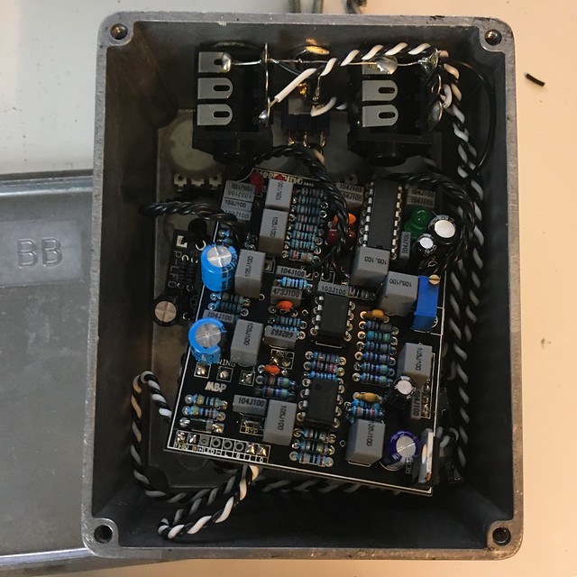
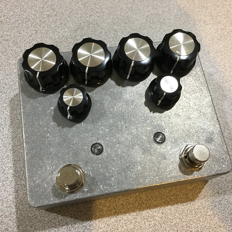
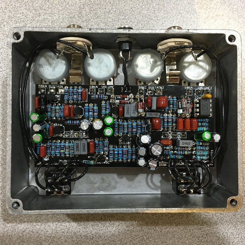
Well, I haven't been too inspired to do anything with outsides lately. More focused on getting all my partial projects complete this month. Here are two more in bare aluminum enclosures. They both sound really great and will likely see some significant use in the future.
Blackhorse Duplex Drive
This is a Cornish SS2 into a (tweaked?) G2. I did the suggested mods in the other build thread. My first 2min with it (quick test after build) I thought it was too bright. However, I played it last night and think it's great as-is. Tone fully CCW and it's a bit too dull and there's plenty of bright on tap so my preferred settings lie somewhere in the middle half of the knob sweep. Win! Isn't it odd how this happens sometimes? I wish I understood why my ears seem to change all the time. It's a good confirmation that if you suddenly don't like a sound you're making, give it a day or two off and try again. You may be surprised. Anyway, it's got a green LED on the SS2 and blue on the G2 and they both sound really nice. Definitely a good amount of gain on tap with both circuits. Not as dynamic as I hoped but it sounds really good. It'll definitely be a front runner for my main OD/Distortion.
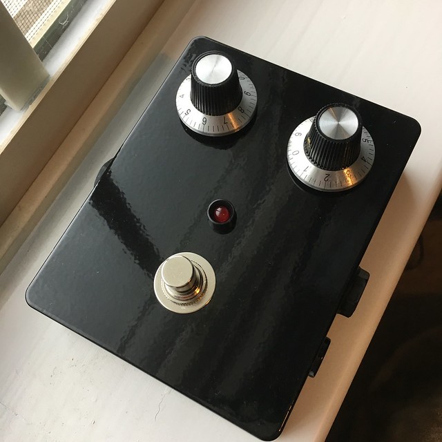
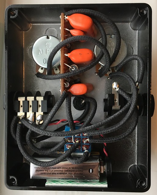
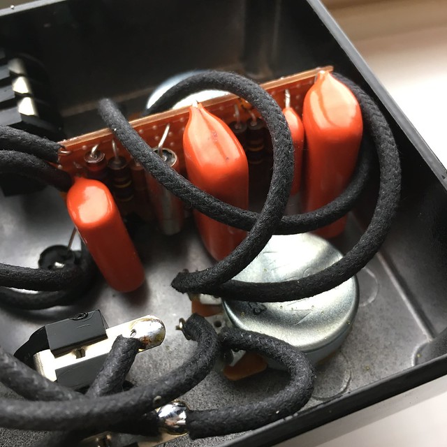
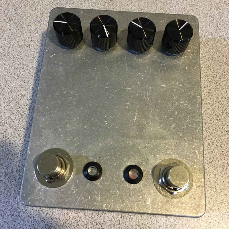
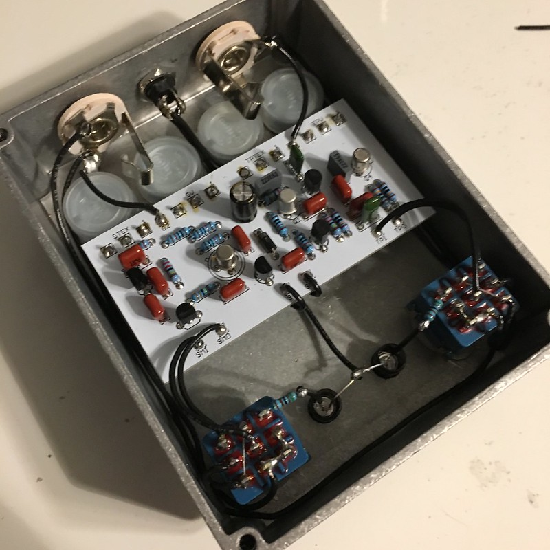
Shoe Gazer Fuzz
This is a clone of the Devi Ever shoe gazer. This is my first experience with her stuff and it's definitely cool. Flanagan did a great job on this board too! It's laid out really well and I had zero issues building with it. It has some crazy fuzz sounds in there. I am looking forward to playing it along side my fat fuzz factory (std 5 knobber with fat switch) and super fat fuzz factory (8 knobber with fat switch and switchable ge/si Q1 transistor) to see if I can duplicate it on those. If I can, I'll stick with the fuzz factory. If not, this one will likely be a second stringer that I add in on occasion like several of my other fuzz pedals.
Blackhorse Duplex Drive
This is a Cornish SS2 into a (tweaked?) G2. I did the suggested mods in the other build thread. My first 2min with it (quick test after build) I thought it was too bright. However, I played it last night and think it's great as-is. Tone fully CCW and it's a bit too dull and there's plenty of bright on tap so my preferred settings lie somewhere in the middle half of the knob sweep. Win! Isn't it odd how this happens sometimes? I wish I understood why my ears seem to change all the time. It's a good confirmation that if you suddenly don't like a sound you're making, give it a day or two off and try again. You may be surprised. Anyway, it's got a green LED on the SS2 and blue on the G2 and they both sound really nice. Definitely a good amount of gain on tap with both circuits. Not as dynamic as I hoped but it sounds really good. It'll definitely be a front runner for my main OD/Distortion.
Shoe Gazer Fuzz
This is a clone of the Devi Ever shoe gazer. This is my first experience with her stuff and it's definitely cool. Flanagan did a great job on this board too! It's laid out really well and I had zero issues building with it. It has some crazy fuzz sounds in there. I am looking forward to playing it along side my fat fuzz factory (std 5 knobber with fat switch) and super fat fuzz factory (8 knobber with fat switch and switchable ge/si Q1 transistor) to see if I can duplicate it on those. If I can, I'll stick with the fuzz factory. If not, this one will likely be a second stringer that I add in on occasion like several of my other fuzz pedals.
#18
Build Reports / Mojo One Knob Fuzz (Vero) | 4-Track Tape Fuzz (GuitarPCB)
January 11, 2017, 06:07:29 AM
First two builds of the year already in the books.
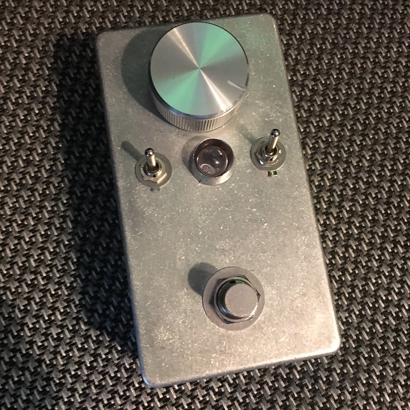
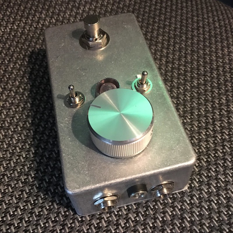
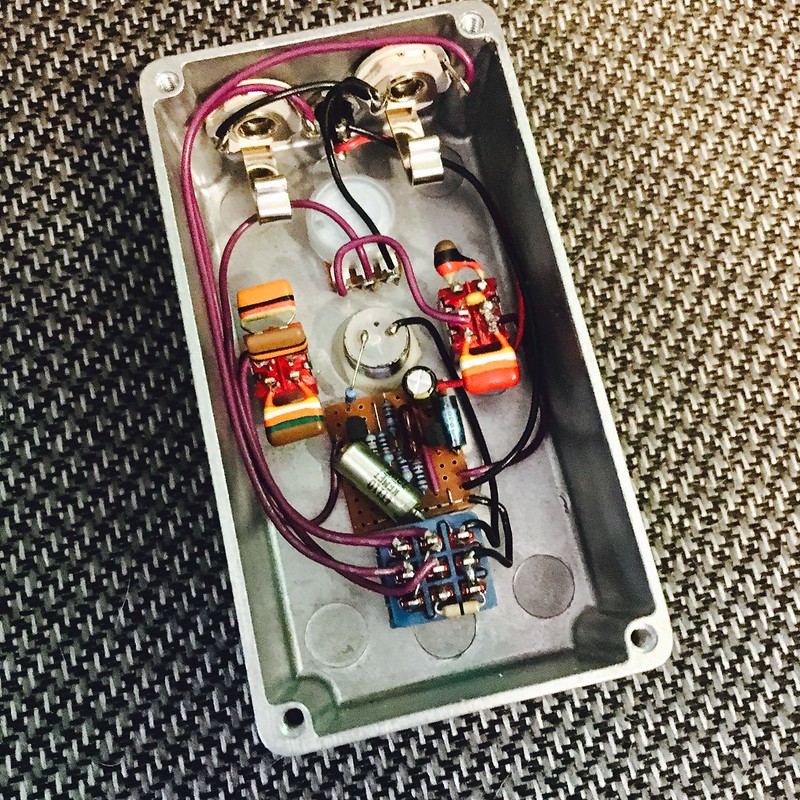
"Mojo" One Knob Fuzz
I have had this on the books for ages and finally got around to it. It looks cool and is surprisingly versatile for just being a one knob job. It is based on the meathead with switchable caps (vero layout from tagboard). I already posted it for sale as I have built a bunch of similar fuzzes and kind of feel like I've outgrown this circuit and don't see it living on my board, unfortunately. It's an awesome sounding fuzz but I'm into more crazy fuzz sounds (MKI, fuzz factory, etc.) and my 2017 goal is to fund a new guitar with gear I don't use and downsize!
In/out caps are tropical fish and I have some cool old axials on the little vero. Finished it off with a monster 10mm red LED and kept it in the raw enclosure as I just liked the unfinished look. Oh and it's got all top jacks. I still haven't found a good template for these and have just given up and started eyeballing my hole centers.
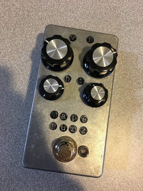
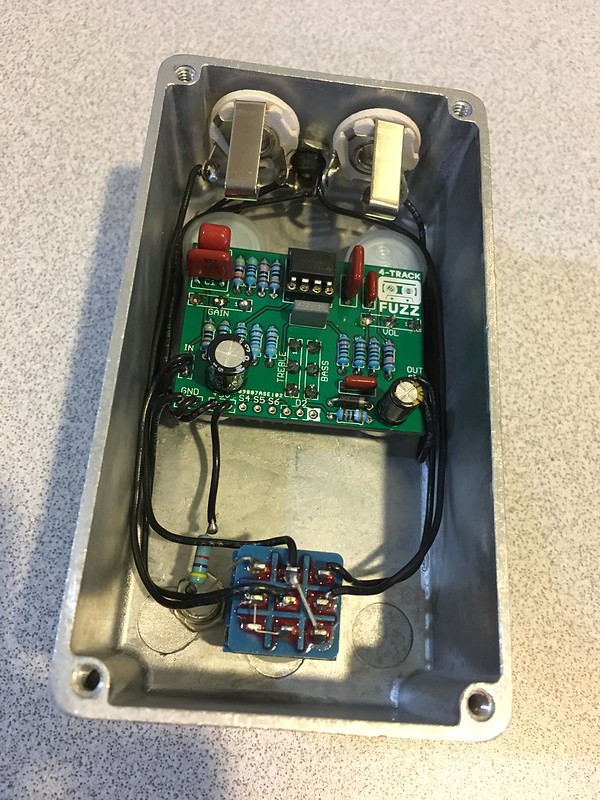
Tape Fuzz
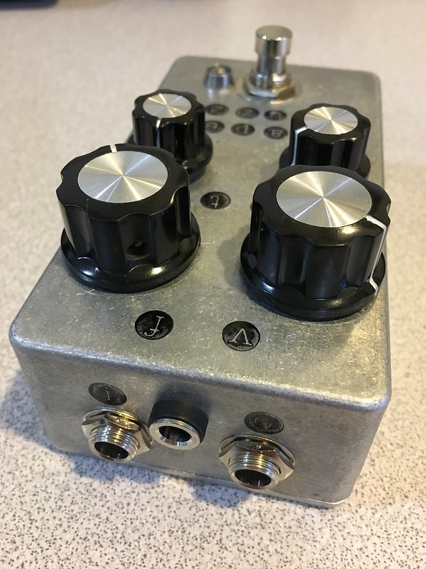
Next up, the guitarPCB 4-track fuzz. This has been in my PCB drawer for months and another of my 2017 resolutions is to complete all my projects I have before embarking on new ones. I will say this one sounds really cool and unique and the EQ is super versatile for getting thick wooly sounds or more cutting sounds. My only complaint is that it currently only sounds good (to me) with the fuzz cranked. I'm going to try some other IC's this weekend to see if something else sounds better or gives me more range on the fuzz control. I think this one is a keeper for me though. And it's my first try at stamping a pedal. Not bad although the offset of the top two control labels (volume and fuzz) is already driving me a little crazy. Ah well. Oh and this is another raw enclosure. Maybe less is more in 2017?
Hoping to knock out a few more this weekend. I feel like it's been weeks since I completed anything but I made a of progress in that time. I'm hoping to have a producting Jan/Feb and knock out most of my PCB drawer and then take a much needed break.
"Mojo" One Knob Fuzz
I have had this on the books for ages and finally got around to it. It looks cool and is surprisingly versatile for just being a one knob job. It is based on the meathead with switchable caps (vero layout from tagboard). I already posted it for sale as I have built a bunch of similar fuzzes and kind of feel like I've outgrown this circuit and don't see it living on my board, unfortunately. It's an awesome sounding fuzz but I'm into more crazy fuzz sounds (MKI, fuzz factory, etc.) and my 2017 goal is to fund a new guitar with gear I don't use and downsize!
In/out caps are tropical fish and I have some cool old axials on the little vero. Finished it off with a monster 10mm red LED and kept it in the raw enclosure as I just liked the unfinished look. Oh and it's got all top jacks. I still haven't found a good template for these and have just given up and started eyeballing my hole centers.
Tape Fuzz
Next up, the guitarPCB 4-track fuzz. This has been in my PCB drawer for months and another of my 2017 resolutions is to complete all my projects I have before embarking on new ones. I will say this one sounds really cool and unique and the EQ is super versatile for getting thick wooly sounds or more cutting sounds. My only complaint is that it currently only sounds good (to me) with the fuzz cranked. I'm going to try some other IC's this weekend to see if something else sounds better or gives me more range on the fuzz control. I think this one is a keeper for me though. And it's my first try at stamping a pedal. Not bad although the offset of the top two control labels (volume and fuzz) is already driving me a little crazy. Ah well. Oh and this is another raw enclosure. Maybe less is more in 2017?
Hoping to knock out a few more this weekend. I feel like it's been weeks since I completed anything but I made a of progress in that time. I'm hoping to have a producting Jan/Feb and knock out most of my PCB drawer and then take a much needed break.
#19
Tech Help - Projects Page / Aion Lab Series Preamp -- bypass LED won't turn off?
January 08, 2017, 01:55:48 PM
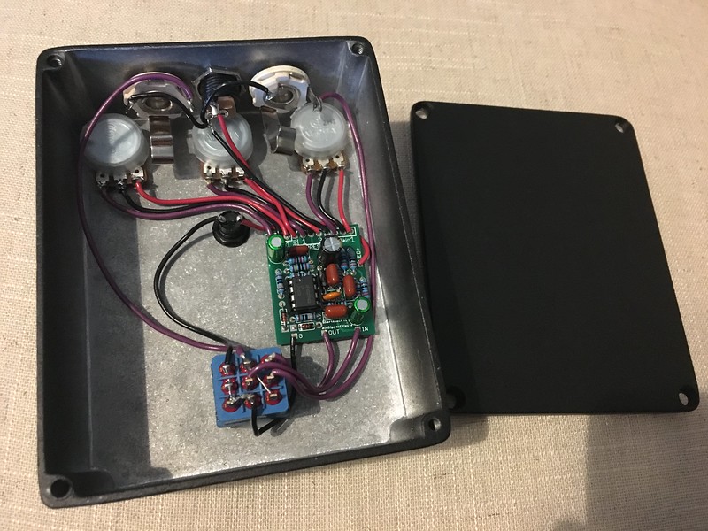
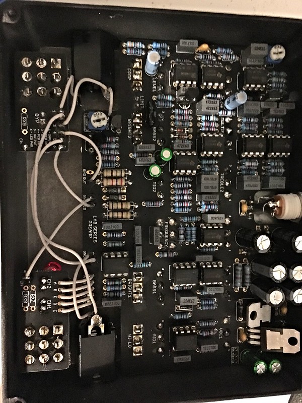
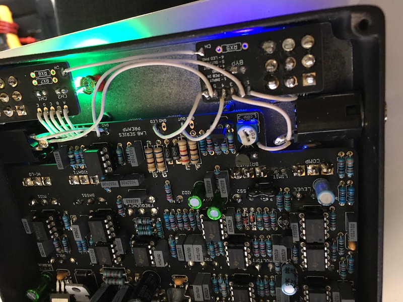
So I finally got a power supply for this and was able to test it out. I haven't calibrated it yet but it appears to be functional. Signal bypass works. However, the LEDs won't turn off (channel LED's and bypass LED) no matter if I bypass the pedal or not. I wired it based on the recommendation in the build doc for LED bypass off operation. I also noticed what appears to be some bleed through when the pedal is bypassed (master volume adds noise when bypassed). I haven't played around with it too much yet but I've checked continuity and the switch appears to be working OK although there is no drawing for how the bypass 3pdt PCB has the thing wired to the rest of the circuit.
I checked and there are no bad solder joints that I can see. Anyone see anything obvious? If I can't get it to work, I may ditch the PCB and wire the 3PDT myself although it'll require some head scratching to make sure I do it correctly with the channel footswitch. My guess is the CH pads are used for the grounding of those LEDs so maybe the solution is to ditch the PCB and just wire the switch directly. But before I do that, is there something obvious to try that I'm missing?
Build Doc: https://aionelectronics.com/wp-content/uploads/2016/04/aion-lab-series-preamp-documentation.pdf

Bypass PCB, other side
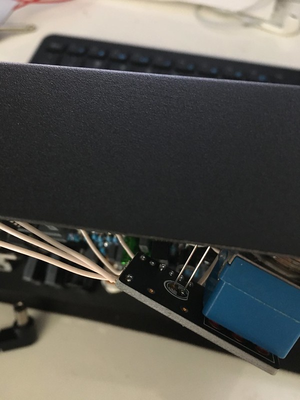
The bleed through has me worried about the switch and PCB still so odds are I'll replace it. Just hoping I'm being dumb and the greater minds here will enlighten me.
Also, I did check and I'm getting +15.3V / -14.7V on the test pads so it appears my power supply and at least part of the circuit are OK. I'll calibrate and debug (if necessary) after I get this issue dealt with. I need to first track down an 1/8" to 1/4" tip converter so I can run a signal generator through it. It sounds pretty good already though.
I checked and there are no bad solder joints that I can see. Anyone see anything obvious? If I can't get it to work, I may ditch the PCB and wire the 3PDT myself although it'll require some head scratching to make sure I do it correctly with the channel footswitch. My guess is the CH pads are used for the grounding of those LEDs so maybe the solution is to ditch the PCB and just wire the switch directly. But before I do that, is there something obvious to try that I'm missing?
Build Doc: https://aionelectronics.com/wp-content/uploads/2016/04/aion-lab-series-preamp-documentation.pdf
Bypass PCB, other side
The bleed through has me worried about the switch and PCB still so odds are I'll replace it. Just hoping I'm being dumb and the greater minds here will enlighten me.
Also, I did check and I'm getting +15.3V / -14.7V on the test pads so it appears my power supply and at least part of the circuit are OK. I'll calibrate and debug (if necessary) after I get this issue dealt with. I need to first track down an 1/8" to 1/4" tip converter so I can run a signal generator through it. It sounds pretty good already though.
#20
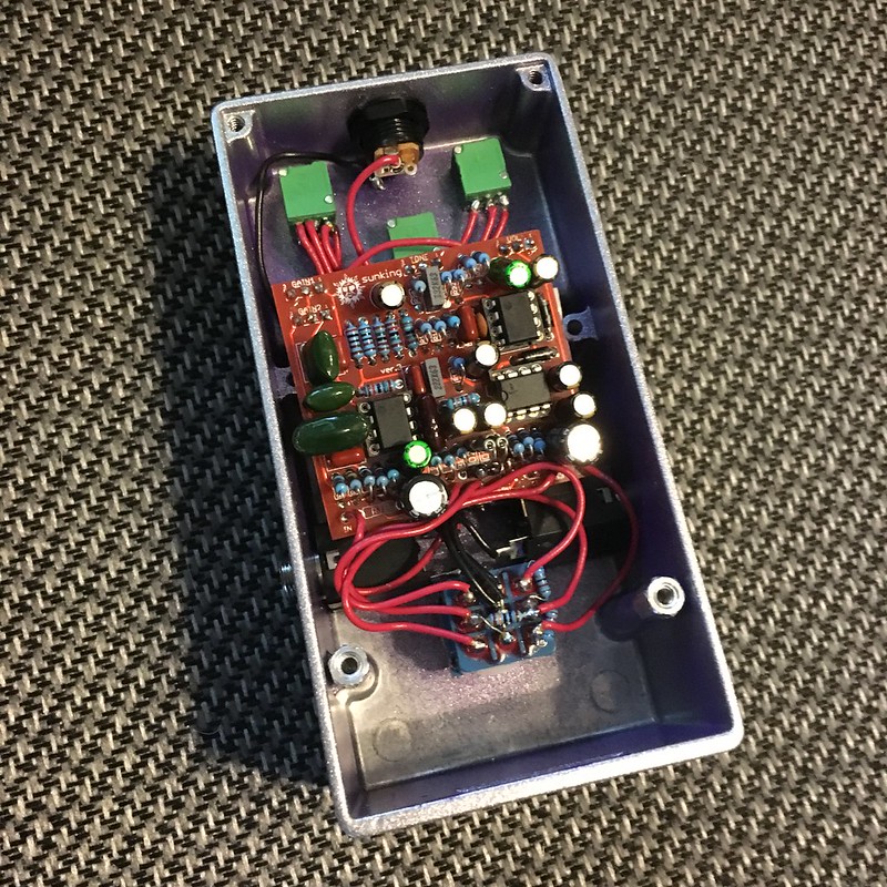
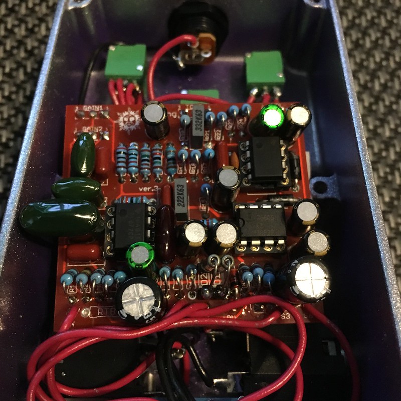
Tech Help - Projects Page / Sunking Build Doc - PCB photo inside
January 03, 2017, 07:31:25 AM
All,
I can't seem to find a build doc that matches with this PCB. Can anyone send it to me or link me to it?
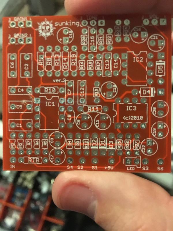
Thanks and happy new year!
I can't seem to find a build doc that matches with this PCB. Can anyone send it to me or link me to it?
Thanks and happy new year!