A grounding issue somewhere would make sense... hm... Any reason I would get a redicution in voltage of a little over a factor of 10?
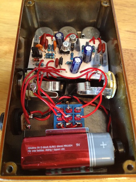
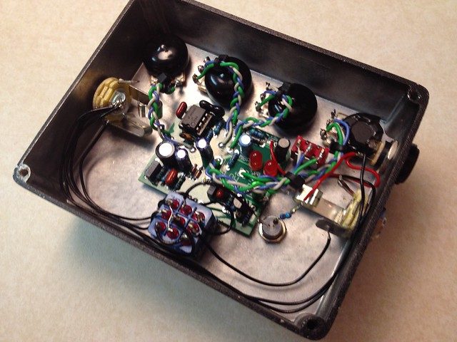
As far as the switch goes, I used a different switch wiring scheme actually... this guy...

It looks odd from the photo but here's how my switch is hooked up (lugs numbered from top left to bottom right, across then down)...
1 - Circuit Board "in"
2 - CLR from LED negative lead (not shown hooked up in the photo though, but it is now)
3 - Circuit Board "out"
4 - Input Jack Tip
5 - Ground (Input Jack Sleeve)
6 - Output Jack Tip
7 - Jumpered to 9 w/ null resistor
8 - Circuit Board "in"
9 - Jumpered to 7 w/ null resistor
So it's slightly rearranged but ultimately I think it's the same (functionally) as the madbean std. wiring diagram.
As far as the switch goes, I used a different switch wiring scheme actually... this guy...
It looks odd from the photo but here's how my switch is hooked up (lugs numbered from top left to bottom right, across then down)...
1 - Circuit Board "in"
2 - CLR from LED negative lead (not shown hooked up in the photo though, but it is now)
3 - Circuit Board "out"
4 - Input Jack Tip
5 - Ground (Input Jack Sleeve)
6 - Output Jack Tip
7 - Jumpered to 9 w/ null resistor
8 - Circuit Board "in"
9 - Jumpered to 7 w/ null resistor
So it's slightly rearranged but ultimately I think it's the same (functionally) as the madbean std. wiring diagram.


 that looks awesome!
 Thanks for all the kind words and I recognize quite a few names here from TGP, D*A*M and BJFe forums