
Let me look up the values and other voltages; I'll report my findings here.
- Welcome to madbeanpedals::forum.
This section allows you to view all posts made by this member. Note that you can only see posts made in areas you currently have access to.
Pages1
#1
Tech Help - Projects Page / Re: Harbinger 1.5- Signal Present When Engaged, No modulation
August 23, 2021, 01:25:33 PM #2
Tech Help - Projects Page / Re: Harbinger 1.5- Signal Present When Engaged, No modulation
August 22, 2021, 10:26:57 PM
Had a first shipment of LT1054s arrive (from a seller on Amazon). I removed the jumper between legs 1 and 8 but still the same issue.
I have another batch from Mouser on order coming soon.
I have another batch from Mouser on order coming soon.
#3
Tech Help - Projects Page / Re: Harbinger 1.5- Signal Present When Engaged, No modulation
August 22, 2021, 06:26:41 AM
Hey there Cybercow, good to see you on the Madbean forums as well.
Unfortunately, firmly seating the transistors had no effect I'm afraid. The lamp does work and dim (very slightly) only when the gain trim pot is cranked all the way up which the user guide states to be wary of so as not to blow the lamp.
Unfortunately, firmly seating the transistors had no effect I'm afraid. The lamp does work and dim (very slightly) only when the gain trim pot is cranked all the way up which the user guide states to be wary of so as not to blow the lamp.
#4
Tech Help - Projects Page / Re: Harbinger 1.5- Signal Present When Engaged, No modulation
August 21, 2021, 05:12:21 PM
Thank you for your reply. Yes, the PCB was tested in the dark and with a bottle cap covered in painter's tape and marked black with a sharpee. Putting on the cap makes no difference I'm afraid.
#5
Tech Help - Projects Page / Harbinger 1.5- Signal Present When Engaged, No modulation
August 21, 2021, 05:36:56 AM
Good evening,
This may be a very stupid post. I have some LT1054 IC chips on order but my impatience got the better of me. I used an SPCA1044 and jumpered pins 1 and 8.
The board fired up fine. The bypass signal is working and I do get signal when the effectis engaged. I don't get any vibrato modulation however. The lamp lights up pretty well when the gain trim control is turned up almost all the way. It does fade in and out like it should when the speed control is adjusted though this is faint. The offset trim pot seems to have no effect.
Barring that IC1 is not the proper part, is it possible anybody else sees something obviously wrong with my board?
#6
General Questions / Re: Mystery of the Tone Virus
March 28, 2021, 09:29:14 PM
I reflowed the solder at those joints. I also checked for continuity on pins 4-6 on IC1; no continuity.
Unfortunately I still get the same 0.24V at pin5 and 8.72V at pin8. Should I maybe replace all the components listed in your post?
Unfortunately I still get the same 0.24V at pin5 and 8.72V at pin8. Should I maybe replace all the components listed in your post?
#7
General Questions / Re: Mystery of the Tone Virus
March 27, 2021, 07:54:16 PM
Took out D1 and still got the same voltages. Reflowed all the joints and am now getting 8.72V on pin 8 of IC1 but 0.24V on pin 5.
I think I might rig up an audio probe and start testing components.
I think I might rig up an audio probe and start testing components.
#8
General Questions / Re: Mystery of the Tone Virus
March 27, 2021, 06:44:02 AM
It looks like something is wrong with the power supply. I did remove all the ICs except IC1. The voltage in pin 8 was 0.65V. I removed IC1 and measured the voltage the same voltage in the socket.
Do you recommend replacing all the components downstream in the power supply?
Do you recommend replacing all the components downstream in the power supply?
#9
General Questions / Re: Mystery of the Tone Virus
March 27, 2021, 02:41:52 AM
Thank you. I will follow your guidance and see what comes.
#10
General Questions / Re: Mystery of the Tone Virus
March 26, 2021, 07:20:30 PM
My apologies, I had my multimeter on the wrong setting.
I am getting
1.73 volts on Pin 1 IC1
0.65 volts on Pin 5 IC5
I am getting
1.73 volts on Pin 1 IC1
0.65 volts on Pin 5 IC5
#11
General Questions / Re: Mystery of the Tone Virus
March 26, 2021, 05:54:02 AM
Apologies for the late reply. I am getting some far out readings.
IC 1 Pin 1 is 17.3v
IC 1 pin 5 is 12.3v
What do you make of it?
IC 1 Pin 1 is 17.3v
IC 1 pin 5 is 12.3v
What do you make of it?
#12
General Questions / Re: Mystery of the Tone Virus
March 25, 2021, 01:13:42 AM
I replaced R2 and R19 as well as reflowed the solder joints on the toggles. The same issue persists still.
The wrong value components in R2 and R19 would not explain why the unit functioned fine and then conked out. Here is a video of the board and the issue.
https://youtube.com/shorts/suaTGtAzm_k
The wrong value components in R2 and R19 would not explain why the unit functioned fine and then conked out. Here is a video of the board and the issue.
https://youtube.com/shorts/suaTGtAzm_k
#13
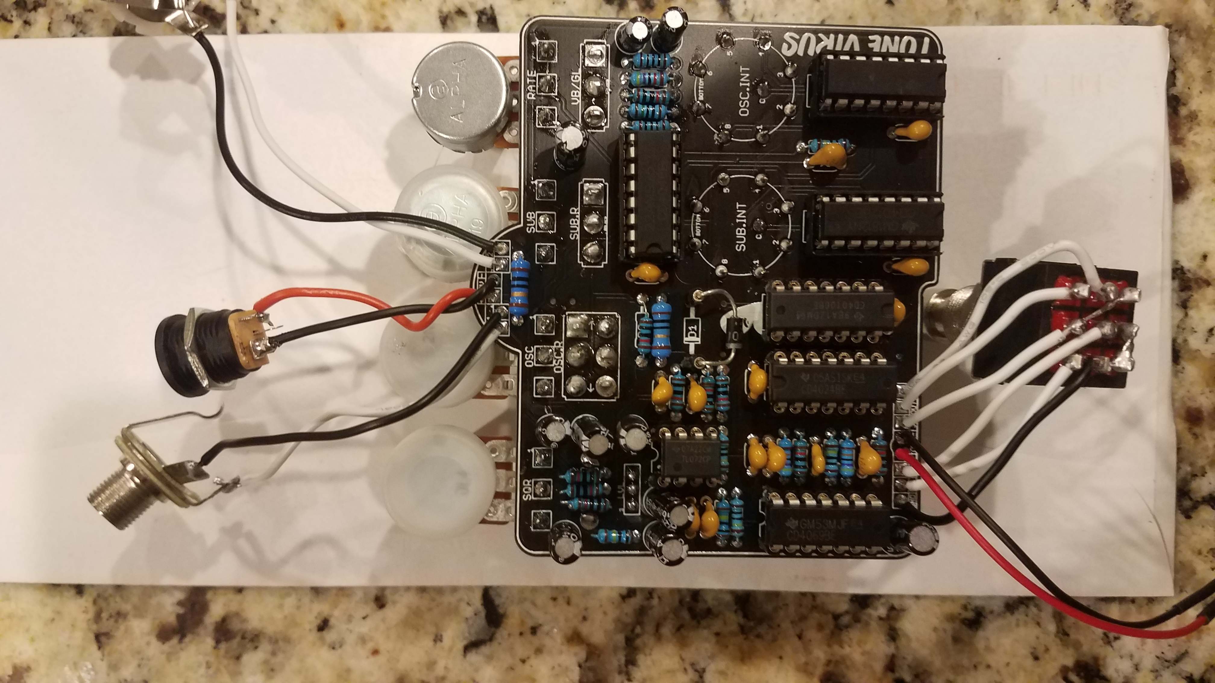
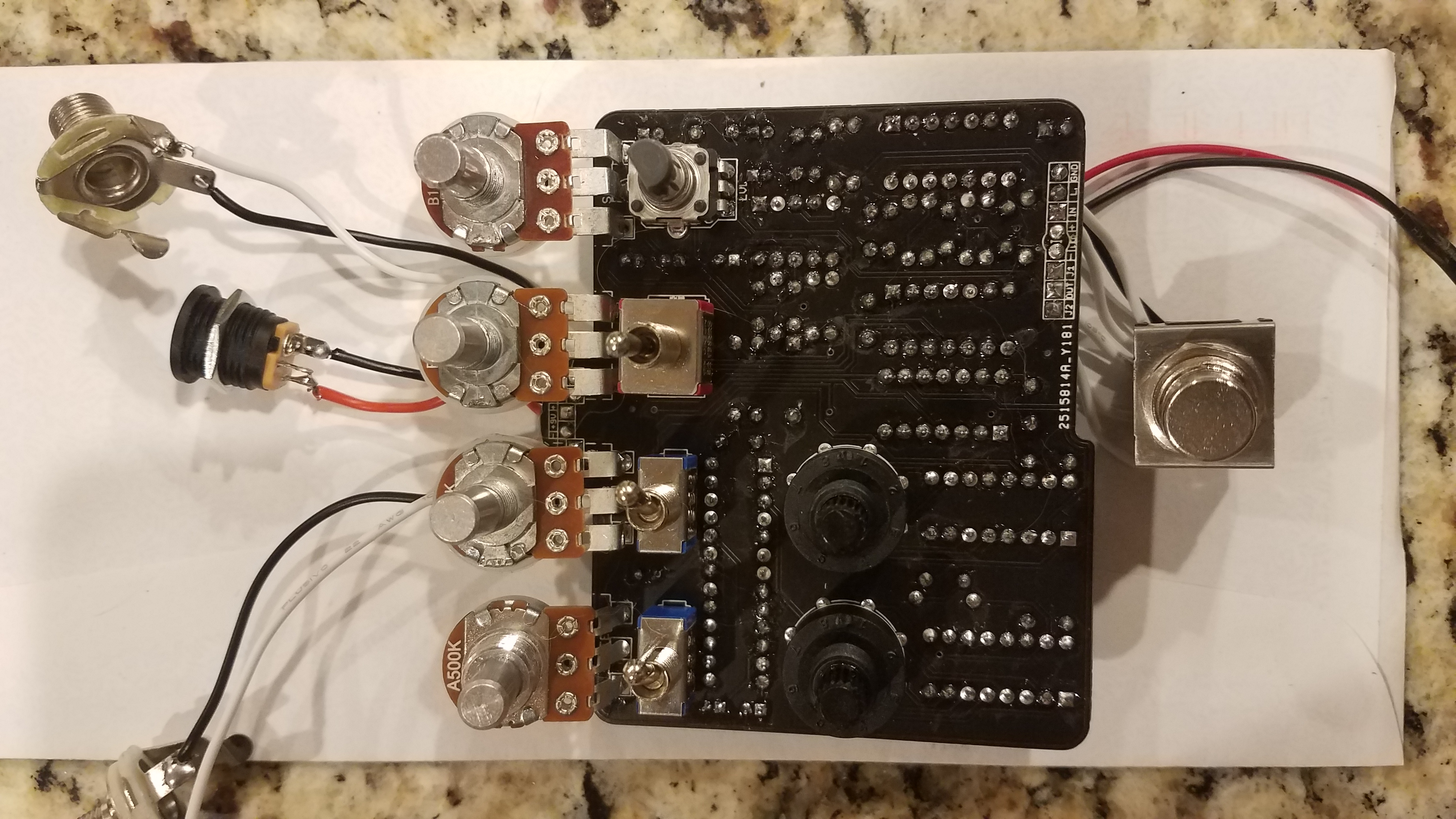
General Questions / Mystery of the Tone Virus
March 24, 2021, 06:21:57 AM
Hello all,
I started building pedals this year and have 50 successful builds under my belt and I would venture to guess 15 or so where I made mistakes. I bought a Tone Virus as I wanted to build a combo pedal with a tremolo for a choppy, synth sound.
My first attempt was partially successful. I was getting square wave fuzz but high pitched squeal on the oscillation knobs from the mixer. Replacing all the IC chips produced no discernible difference. I bought a second board and finished wiring it up. It worked as it should upon firing it up however the LED did not power up despite testing good with a disc battery. I took the board out of the enclosure, rewired the LED and popped the whole thing back in. Now there is no signal and a putting sound from the oscillator.
I guess third time's the charm but I'd rather figure out what's going on with this board given it was working the first time around. Any help would be greatly be appreciated.
A follow up question, would anybody be interested in taking this in to troubleshoot and solve? Please PM if interested.
Pages1