
Okey dokes I'll do a quick scan of the parts tomorrow when I get my eyes some rest!
- Welcome to madbeanpedals::forum.
This section allows you to view all posts made by this member. Note that you can only see posts made in areas you currently have access to.
#16
Tech Help - Projects Page / Re: Colorsound Overdriver only really works with gain on full
August 28, 2016, 03:01:46 AM #17
Tech Help - Projects Page / Colorsound Overdriver only really works with gain on full
August 28, 2016, 02:15:38 AM
So I built the CTO v2 for a friend here http://www.guitarpcb.com/apps/webstore/products/show/3436319
And it sounds great..... unless the gain is anywhere except fully clockwise. I get a pretty nice fuzz tone with the gain on 10 but as soon as you move it to 9.8 the circuit completely cleans up and the gain knob doesn't really do too much from 0-9.9. I checked the sweep on the gain knob with an ohmeter and the resistance changes linearly so I'm not sure why I get this very nonlinear response.
Thoughts?
#18
General Questions / Supreaux Deux Often FX Build Doc
August 18, 2016, 05:38:38 AMNvm I found it with some digging! If anyone else starts looking for this it's here
https://docs.google.com/file/d/0B46z2J0FljLkeVpTMnVmeFJiU2s/edit?pli=1
#19
General Questions / Re: Help Identifying PCB
August 10, 2016, 06:07:36 PM
Wow thanks guys! Never would have gotten that by myself:)
#20
General Questions / Help Identifying PCB
August 10, 2016, 05:15:10 PM
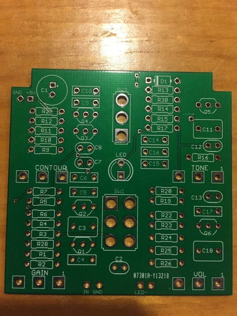
I found this PCB that looks really interesting and like something I'd be interested in making however I really have no idea what it is. First though was a Rat but it has 6 transistors so maybe muff? I'm not really sure, but it looks fun. Anyone know what this thing is or where I can find a doc for it?

#21
Tech Help - Projects Page / Re: 4:1 Compressor LED
August 05, 2016, 04:52:34 PM
Also I just watched a demo of the 4:1 and mine seems to have much more output. Unity is around 9 o clock but madbeans demo has much less output. Anything specifically I should check for?
#22
Tech Help - Projects Page / Re: 4:1 Compressor LED
August 05, 2016, 04:41:26 PM
Ahh makes sense. Thanks! Vero is a great trick I might have to try. The holes are just so dang tiny on these power jacks
#23
Tech Help - Projects Page / Re: 4:1 Compressor LED
August 05, 2016, 06:10:40 AM
Dont want to start another thread for this but I can't seem to get LED wiring to work how I feel it should with 2 in 1 pedals.
I've built a few and first I normally try running the pedals 9v tap and a single CLR to the 9v pos of the power supply and then 2 wires coming from the other end of the resistor each going to a separate LED, but for some reason when I do this I can't have both LEDs lit at once. To do this I always have to take 2 separate resistors to the + power supply.
1. What are the layman physics behind this phenomenon and why doesn't my way work?
2. Is there a better way than trying to get 3 separate wires going into the +9v (2 CLRs and the board +9v tap)?
#24
Tech Help - Projects Page / Re: 4:1 Compressor LED
August 03, 2016, 04:28:35 AM
Awesome thanks so much!
#25
Tech Help - Projects Page / Re: 4:1 Compressor LED
August 02, 2016, 03:41:56 PM
Thanks for all the help with this guys! I tried all the solutions here but it wasn't working so I went to square 1 took the 3pdt switch out and lugs 2, 5, and 8 were always in continuity regardless of switch position. Really odd because I'm almost positive I didn't fry it. I have pretty solid solder work nowadays. Also just so I don't open a new thread what is the benefits of madbeans true bypass vs the one I was using?
#26
Tech Help - Projects Page / Re: 4:1 Compressor LED
July 30, 2016, 05:22:38 AM
Its possible I guess. I can try and check tomorrow. It's soldered to the board and going straight into a fresnel lens so that should be obvious but I have tired eyes from working all day on some pedals.
#27
Tech Help - Projects Page / 4:1 Compressor LED
July 30, 2016, 04:16:36 AM
So this seems like it should be obvious but for some reason my 4:1 compressor LED is always on. Everything else works fine. Right now I have negative on PSU to neg and pos to pos.
If you number the 3pdt switch as
1 2 3
4 5 6
7 8 9
I have the G pad going to output jack sleeve and output sleeve going to lug 5 then I have the L pad going to 2 with effect in at 1 effect out at 3 input ring to 4 output ring to 6 and 7 and 9 jumpered. Its obviously being grounded in both switch positions somehow but I can't figure out why. The schematic shows the ground pad as general ground which goes to output sleeve and then middle lug, but somehow in both position LED neg has continuity with ground? Those are all the connections I have on this board. Thoughts?
#28
General Questions / Re: 125B Sideways Drilling Template
July 12, 2016, 06:58:17 AM
Yeah I realized it had board mounted pots so I went with a 125B sideways with top mounted pots and I just bought 16mm solder lug pots and will wire the pots manually 
#29
General Questions / Re: 125B Sideways Drilling Template
July 08, 2016, 06:07:15 PM
Ah yes, I forgot about those etches! I'll probably be picking up the krankosaurus board then. I have all pretty small components. Still have a good stock of those mini electros. Any more opinions?
#30
General Questions / 125B Sideways Drilling Template
July 08, 2016, 05:29:26 PM
Hey guys, been out of the game for a long time, but I've picked it back up with some free time and a lot more guitar playing. So Im really wanting to do a Box of Rock to round out my overdrive section. The thing is I love top mounted jacks, so is it possible to use a 125B enclosure with top mounted jacks (being oriented sideways) that wouldn't interfere with a pot mounted pcb? Also, since I'm here is there any other PCB to purchase for this besides the Tayda one? my google-fu couldn't pull up anything else really and I'm kind of done with vero at this point in my life.