News:

Forum may be experiencing issues.

Main Menu
Menu

Show posts

This section allows you to view all posts made by this member. Note that you can only see posts made in areas you currently have access to.

Show posts Menu

Topics - lincolnic

#41
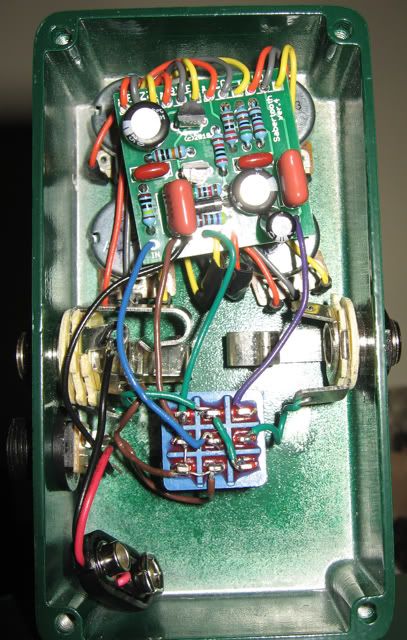
And before anyone says it, yes, the transistors are first.

So I'm gearing up to build a Mk I or Mk II (probably going to do a Mk II, just for ease), and I know there's a lot of room for experimentation in these circuits. For those of you with more experience, which components have you found the most beneficial to play around with? I'd guess at least the input and output caps, but I'm open to suggestions as far as anything else I should try.
#42
I'm looking at the Pastyface build doc, and one of the component sets is labelled "Sola Sound Tonebender". I know that Sola Sound produced a bunch of versions - which is the one in the Pastyface build doc? I'm guessing Mk I, I.V, or II, since there's a separate set of components listed for the Vox Mk III. Thanks!
#43
Build Reports / Neptune+
January 09, 2013, 04:52:28 AM
I'm not sure if this actually deserves a "+" in the name, but I threw a couple of mods onto the Neptune, so that's how I've been thinking of it since. Bought the board in the last group buy (April 2012?), populated it sometime in the fall, and finally boxed it up right before the end of the year. I had an issue with the switch popping, and my thanks goes to midwayfair, culturejam, and LaceSensor for teaching me a bit about the circuit and how to deal with that.

Okay, so the mods - nothing fancy, but I think they're useful. When I saw in the build doc that R17 set the overall range of delay times, and that the stock minimum was ~200 ms, I knew that I'd want a shorter option for something slapback-y. I wired up a DPDT instead of R17 to select between two resistors - that's the Short/Long switch on the left. "Long" is the stock 18k, and I have 10k on the other side for a shorter setting. I may replace that with an even smaller resistor at some point; it gets close to the slapback I'm imagining, but not quite there.

As for the second mod, I used eldanko's mod from his Dory Deluxe build to switch the momentary between the stock warp option and infinite repeats. I was pleasantly surprised by how long you can let it oscillate before it gets painfully loud.

If I was going to build another one, I might try messing with R18 to slow down the modulation a bit...maybe I'd replace it with a trimmer to experiment a bit more. I probably won't build another soon, though - so much wiring! This pedal has made me seriously consider using ribbon cable in the future. Contrary to the gutshot here, it actually looks a little neater in person. There's actually plenty of clearance between the 1M resistor on the switch and the enclosure wall, but in the photo it looks like they're touching. Same goes for the bottom left corner of the PCB. Must've just been a bad angle. I think that yellow input wire was originally meant to go underneath the PCB, but I'm not sure why it ended up on the top...I probably just ran out of patience and wanted to play with my new delay already!

I have to say, even though the wiring was a pain, this pedal made me appreciate the DIY experience that much more. It's a nice confidence boost when you know that you couldn't buy the same pedal in a store.

But enough talk - have at you!


#44
Well, I've finally run into the dreaded popping switch. In over 20 builds, I've never had this problem, but my Neptune seems to be set on breaking the streak. I tried putting a 1M resistor between input and ground on the switch (with alligator clips, to see if it'd work) - no help. I reflowed my connections at the switch and the in/out jacks in case there was a cold joint somewhere, and still no luck.

Oddly enough, the pop seems to be significantly lessened (if not eliminated altogether) when nothing's plugged into the input, much like the problem Jon was having with his Joshua Tree build.

I've read the Jack Deville article, as well as the AMZ one about LEDs. I don't think it's the LED, as the Neptune isn't exactly a high gain pedal. Any other advice?
#45
A guitarist I work with asked me to build him a clone of the big wedge Maestro MFZ-1. I decided it would be a good chance to jump into the world of vero, and it was pretty fun!


I picked this color specifically because it reminded me of a car from the 50s...or possibly a fridge.

The three box caps to the left of the IC didn't have long enough leads to get where they needed to be, so I had to solder extra leads (leftover from some resistors, I think) onto one side of them first. Kind of silly, but it worked!

I've been digging around http://tagboardeffects.blogspot.com/, and I foresee a few other vero builds in my future.
#46
Hey guys,

I don't know if anyone here buys from veroboard.com, but I got some stripboard from Amazon the other day and it came with an unlimited use coupon for 15% off until 10/31. Figured I'd share! The coupon code is W1E8DJ1A2N.
#47
Hey guys,

Does anyone have documentation for the Road Rage ver. 3? This would be the PCB that predates the 2011 version currently in the archive, I think. I got it maybe two years ago, when Brian was graciously throwing them in with any orders during the holiday season (thanks Brian!), but I never had a use for it until now. I did a forum search, but didn't find anything...hopefully I didn't just miss something obvious. If this turns up, I'd really appreciate it.

Thanks!
#48
Build Reports / Doombutter w/ fuzz lift
August 29, 2012, 06:01:16 PM
After sitting unboxed on my desk for months, I've finally boxed this guy up. It's super wacky, but a lot of fun. It'll take a little experimenting to find some good settings, but hopefully I can come up with some musical uses for it. The enclosure is PPP's Blue Hammertone, with a white LED.

I used LDR #9203 from Small Bear, which was the closest I could find to the recommended specs. It sounds fine to me, and I can't think of any reason to swap it out, so I'll save the other LDR I bought for an upcoming Neptune build.

I added the fuzz lift switch, which doesn't seem to remove the fuzz as much as make it just a bit quieter. I'm using single coils (Strat/Jazzmaster), so who knows. Still a fairly useful thing to have, and it's such a simple mod that there's hardly any reason not to include it. At first I tried wiring my LED up for Brian's suggested rate mod (i.e., positive lead goes to lug 2 of the Track pot), but it didn't work as I expected. Rather than being an on/off indicator and flashing constantly to show the rate, it would only show the pedal's settings when I played through it. If the pedal was engaged and I wasn't playing, then the LED didn't light. It was cool to look at, but ultimately not that useful, so I went back to the standard on/off LED indicator action.

This was the first drilling layout I designed solely on my own, and it turned out very well. The Depth knob accidentally was drilled too far to the right, and I didn't notice until it was too late, but worse things have happened. I did my usual sloppy hand-labeling with a black Sharpie paint pen.

The wiring isn't pristine, but I'm definitely making progress. This is probably the neatest wiring I've done yet. And the pedal fired up with no issues, so hooray for that!


#49
An open question for people who are more knowledgeable than myself:

The studio where I work has a box where we occasionally offer excess stuff to whoever wants it, for free. I was looking in there today and there was a super beat up Boss Super Chorus (missing the backplate and two knobs), with a piece of tape on it that said "Might work?". Peeking at the circuit board, I saw it had an MN3007 in there. I want to take the pedal for parts, but I know the MN3007 is generally used in choruses or flangers. I'm generally not too interested in those kinds of effects, so I got to wondering if there were any other kinds of projects that use the same chip.

Any ideas?
#50
Build Reports / JMK Op-Amp Muff
June 10, 2012, 06:09:41 PM
Nothing particularly showy about this build, but this pedal sounds so good I wanted to talk about it some more. I've had my sights set on an op-amp Muff for a while, and I'm not disappointed. It sounds especially great with baritone guitar. Who wants to start a doom band?

Special thanks to Keefe for the etch, and everyone who helped me troubleshoot an annoying short in the Tech Help section.

The powdercoat is Penny Vein from PPP. I used the script for a project I was working on as a backdrop, because everyone likes binder clips:


Through some trick of photography, the backplate looks much smaller than the enclosure here. Not sure why!

#51
Hey guys.

I finished up Jacob's Op-Amp Muff last night, and did a quick test before I had to run out the door - no knobs or backplate on the enclosure, but it sounded great. Today, I put knobs and the back on to test it for real, and the LED lit up, but suddenly I had no signal when the pedal is engaged or in bypass. It was a bit of a tight fit, so I figured maybe something was shorting out against the backplate. I covered the inside of the backplate with electrical tape, and also a few spots on the bottom of the PCB where it looked like it might hit the jacks - nothing. Took off the backplate and the knobs to recreate the working scenario from yesterday - still nothing.

Time to break out the DMM and signal tester. I traced the schematic down and got signal all the way through - until the volume pot. I have no signal coming out of lug two of the pot now, no matter where the knob is set. I reflowed all three solder joints just in case, but no luck. I'm not entirely sure this is the problem. Since I'm not getting signal when the pedal is in bypass either, I checked continuity between my jacks and my switch wiring, and that all checks out fine. If I'm getting continuity between the jacks, how come I'm not getting signal in bypass?

This is pretty frustrating, so I'm hoping one of you fine people can help me sort this. Literally the only things that changed between last night and today are that I put knobs and the backplate on. (I also tightened up the jacks a little, but I'd be pretty surprised if that's causing any trouble.) Photos below. I'm not a good photographer, so there are a few different pictures of the PCB to hopefully try and avoid glare from the camera flash. Thanks in advance, friends!


And a photo I took before this all went down, which shows the topside and wiring:

#52
I was hoping I'd never have to make a thread like this, but my time has come. I built up my Flapjack today (no parts substitutions), super excited, and...it just doesn't work. I get signal in bypass, but with the switch engaged, I get no sound and the LED doesn't light up.

I've never had a build not fire up immediately, so I was cocky and boxed it up first (I know, I know). I've double-checked my wiring, parts orientation, and component values. I don't quite understand how to take DC readings with my meter, but I checked continuity between all my wiring points and that's all fine. I also checked continuity between the lugs on my 3PDT, that's fine too. The fact that the LED doesn't light up makes me think that maybe the board isn't getting 9V, but I've got continuity between my jack and the board.

I tried probing around with my signal tester, but my skills were only meager enough to take it through the first two resistors...then I got overwhelmed.

Any help would be much appreciated. Sorry in advance for the picture quality:


#53
Hey guys,

I'm looking forward to building up this Flapjack PCB, and I was wondering if anyone had any experience in using a 10kB pot for Gain rather than the stock 50kC. What could I expect using one versus the other? I don't really have the inclination to try them both out, frankly, but if any of you have I'd love to hear your thoughts. Thanks!
#54
Audio/Video Demos / Jonathan Coulton plays my Sabertooth
November 23, 2011, 06:15:35 PM


I engineered this about a month ago, at the studio where I work. If anyone's curious, that's a plain old Squire bass into the Sabertooth, into our '66 Ampeg B-15.
#55
Tech Help - Projects Page / Doombutter LDR help
November 15, 2011, 03:55:16 AM
Hi guys.

I asked about this briefly in the main Doombutter thread, but I'm still a bit confused about what to put in this pedal. If I'm using an LDR, I need an LED to shine on it, right? Is that what D2 is for here? Can I use a vactrol in place of the LED/LDR combo? Any reasons to do one or the other?

Thanks a lot.
#56
Tech Help - Projects Page / Shielded wire question
September 01, 2011, 10:34:06 PM
Hey guys,

I'm probably going to wire up my Poindexter build in the next day or two, and I'm a little unsure of where exactly I should be using shielded wire. Should it go between my in/out jacks and the switch, or between the switch and PCB? Every explanation I can find about how to use shielded wire makes me think it should be between the jacks and the switch, but I figured I should double check and ask before I start soldering.

One more question: if I shield the input and output, would it be okay to solder each wire's shield to its respective jack (i.e. input to the input sleeve, output to output sleeve) or should I have the shields wired to the same ground?

Thanks in advance.
#57
Build Reports / A Tooth and a half
January 06, 2011, 03:24:41 AM
Finished putting together my Sabertooth today. I used to have a Mammoth, but I sold it a while ago. I'm glad to have this sound again. Bright white LED! I had to splice my LED wires because I made the awesome mistake of soldering it to the board before I remembered that I had to load the bezel from the outside of the enclosure. Derp.

I relabeled the "Bite" knob as "Pulse Width", since I like to know what the control's actually doing.


The enclosure's a little scratched because I forgot to tape over it before I started drilling.


I also built another one, but I only have a quick phone picture of it. No gutshot. I made it for a friend of mine who is an actual rock star - it's a pretty good feeling to know that something you made will be used by someone who actually plays music for a living.

#58
Build Reports / A pair of Krankosaurii
January 04, 2011, 06:19:12 PM
The gray one is for a friend, the green one is all mine. They look similar in these pictures, but the gray one is much darker in real life. They've both got red LEDs for the distortion side, and blue for the boost, but it's hard to take a picture of that.

The wiring started out neat, but got kind of messy quickly. I have trouble keeping my wiring neat, but hopefully posting these publicly will help me shame myself into cleaner builds. I've got plenty more on the way.

Aesthetics aside, I think they sound great. Special thanks to mjcyates for supplying the 2.2n caps in my time of need!


#59
Hey guys,

I'm building a Krankosaurus, and I only notice now that C5 (1 uF) is supposed to be an electrolytic. I was only able to find this value as a box cap from Small Bear. Can I use what I've got, or does it have to be electrolytic?

If it does have to be electrolytic, does anyone have two of them to spare? I'd be much happier sending you the dollar for postage than putting in an order just for two caps. Thanks!
#60
I'm having a lot of trouble finding a 2n cap for my Krankosaurus build, can't seem to find one on PPP, SB, or Mouser. Can I substitute 2.2n instead? How will that affect the sound? Thanks for the help.