News:

Forum may be experiencing issues.

Main Menu
Menu

Show posts

This section allows you to view all posts made by this member. Note that you can only see posts made in areas you currently have access to.

Show posts Menu

Topics - Aentons

#41
Build Reports / Modular Multi Mega
January 11, 2021, 12:15:18 AM
This is an experimental prototype Eurorack floor case with single pedals converted to modules.

It uses Vector TS169 rails with Schroff 2.5mm threaded nut rail inserts.

The case is 84HP wide and 3U high.
The panels are 12 HP each. (5.1X2.4")
The filler and IO panel are 6 HP. (5.1X1.2")

The panels are custom cut 0.09" thick 6061 aluminum sheet from onlinemetals.com.

The sides are aluminum angle from the local hardware store and cut to length on a chop saw.

The wood strips on the front and back are poplar that have been tinted with a stain pen.

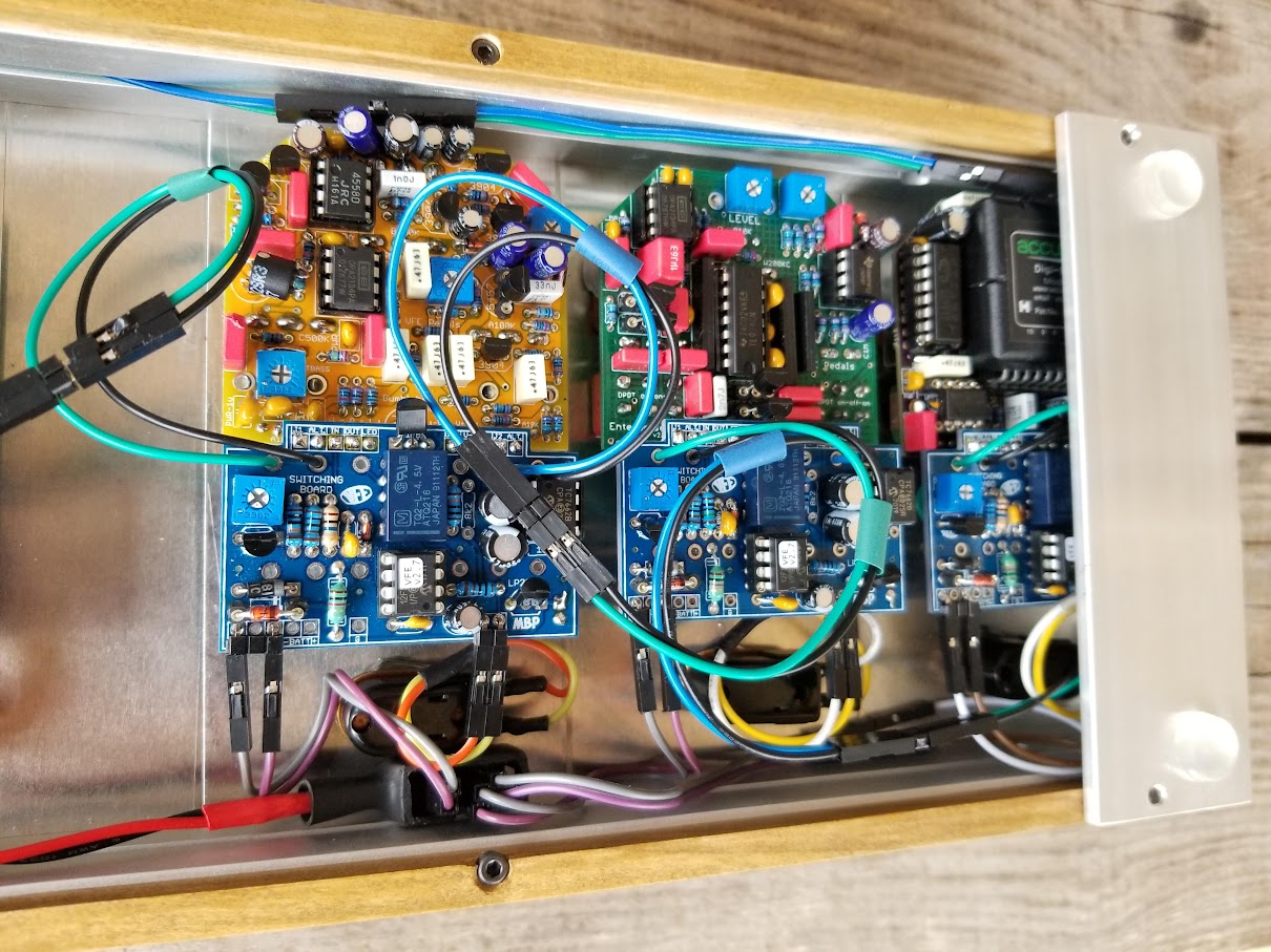
The wiring is mostly using 2.5mm Crimp connectors. (Tayda SKUs A-1060, A-1062)

The 3 faceplates on the right (TS, AD, FRH) are printable inkjet stickers on top, and color adhesive vinyl on bottom of a .03" clear plastic sheet.

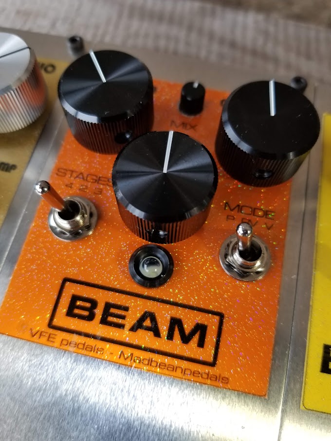
The 3 faceplates on the left are inkjet transparencies printed in reverse, glitter sprayed, and then color sprayed on the print side. I also added a layer of removable sticky stuff to keep them laid down. These 3 faceplates are actually washable. The faceplates were originally made this size so that the faceplate and internal circuit could be transferred to different double and triple pedal enclosure sizes if desired.

It is powered via the P3 system (Phantom Pedal Power) which sends 9v power over the ring, audio on the tip, and a shared ground on a regular TRS stereo cable. (You can probably make an adapter to do this with a OneSpot, I just haven't tried it yet)

Modules pictured in the case are:
MB/VFE The Scream
MB/VFE Alpha Dog
MB/VFE Fiery Red Horse
MB/VFE Bumblebee
MB/VFE Tractor Beam
MB/VFE Yodeler

Other Modules:
MB/VFE Choral Reef
MB/VFE Old School
MB/VFE White Horse
BYOC Overdrive II


#42
General Questions / Matching JFets for first time
December 31, 2020, 05:39:32 PM
I have bread boarded a few of the jfet matcher circuits including geofex and the similar one in the nom-nom doc and I'm not having much luck. They either give me the same reading for all trannies or always measure half voltage whether a trannie is connected or not.

I tried the runoff groove tester for Vp and it seems to give each one a slightly different reading but the trannie gets really hot, really quickly.
http://runoffgroove.com/fetzertech10.png

I have seen a lot of folks over the years that have issues with the geofex one and the solution is usually just to build the similar one at runoff groove.

Also, I just have a cheap digital multimeter. Trying to match J113's

What am I doing wrong? Any tips or tricks?
#43
Open Discussion / SolidGoldFX Surf Rider III schematic
November 20, 2020, 12:50:30 AM
Anybody have a schematic for the SolidGoldFX Surf Rider III? I know it uses a Belton brick, just wondering how it gets the spring sound out of it.
#44
Does buying Electrolytic caps with a higher voltage rating than required help extend the lifetime? I haven't looked at many de-rating charts so I'm not sure if they address this specific question.

For instance, if I need a cap rated at 16v. All other factors being equal, which would be the better choice? A 5000hr rated 16v cap, or a 2000hr rated 50v cap?
#45
Open Discussion / Tayda Cap quality
November 15, 2020, 08:00:30 PM
Anybody ordering Wima and/or Kemet box caps from Tayda? How's that going so far?
#46
Putting this here to gather any interest or ideas?

I understand this is a moonshoot type request but as they say, you'll never get it unless you ask...

I'd like a...
Deluxe Memory Man with negative ground... in a 1590B

It would be nice to have a charge pump built-in but 18v would be ok too. Just please no positive ground.

Other nice to haves would be:
- variable adjust rate and depth
- variable adjust low highpass filter on the repeats ( like on the Deluxe Memory Boy)
- one chip short delay switch (like on dc echo)


Thanks for listening to all the ranting Brian
#47
I have a midrange 80s Charvel Fusion super strat that belonged to my late brother and one of my kids has claimed it. It has a "Made in Germany by Schaller" licensed Jackson branded Floyd Rose bridge. Many of the M3 size saddle screw holes for intonation that go down into the baseplate are stripped from over-tightening. I don't want to replace it and I'd like any fix to be solid for the long term.

I was originally going to just fill with JB Weld and re-tap but I'm afraid that it will just strip out again and I'm also unsure if JB Weld is even ok to use on the cheap "pot metal" or whatever the baseplate is made of.

I've seen most questions like this suggest helicoils or other threaded inserts but others say that those are a one-time use and will deform and back out if you ever remove the screw.

(Edit: I forgot to mention, an M4 is too wide to fit between the saddle "forks")

Anyone have any suggestions for a fix?
#48
Open Discussion / Parasit Studio on Great Scott YT
October 06, 2020, 03:28:45 PM

#49
VFE Projects / Vfe Blueprint Cap subs?
July 05, 2020, 07:12:43 PM
Im curious if C12(.1u) & C14(1u) are doing much of anything other than decoupling? What would be the overall effect of making them both 4.7u? Would it just be kind of darker overall, or just murkier on the repeats?
#50
How do you read the poles and positions from the code on the back of Alpha rotary pots?

I have a 4J3 pot as seen in pic. Does that tell me its 4P3T or 3P4T? Thanks!
#51
The build docs for both the Pepper Spray projects have this:

"1n695  or, 1n34a"
"2n3965 or, BAT41"

"You can use BAT41 diodes as subs for the 1n695"

And then it goes on to talk about the 2n3565 rather than 2n3965, but 3965 is what appears in all the diagrams.

So...
- I can see from the pic in the doc that the appropriate sub for the 1n695 is indeed the BAT41.
- I think I remember reading that the 3965 was a mistake and it should be 3565, but just want to make sure.
- Is the 1n34a just a mistake or is it actually a sub for something?

#52
Has anyone come up with a way to socket an FV-1 on to a board that has SMD pads like the Headtrip?

The only socket type thing I see for SOIC chips are those expensive giant testers like from adafruit. nope.
https://www.adafruit.com/product/1281

However, I do see some SOJ sockets, but, those require the bent under type pins. Anybody tried something like this?
https://www.ebay.com/p/16012048571

You can see it a little better in this 40-pin version
#53
Anyone know of a patch that emulates the Topanga or does a really good 6G15 spring sound? Not just the builtin type blackface reverb but the standalone units.

#54
I watched this video about carbon comp resistor noise and it got me thinking:
[youtube width=480 height=640]https://www.youtube.com/watch?v=yWj5rQRM6Ls[/youtube]

Not quite sure how to word this but I'll try... The Hi-fi audio world is normally concerned with signal fidelity and we here on this forum tend to explore the world of signal distortion and its myriad forms. So with the exploratory and learning spirit in mind...

I'm curious about various ways of how purposely engineered noise (or distortion) on an audio signal could potentially make it sound different or more interesting or more "complex" but not necessarily with just odd/even harmonics. Take for instance, the use of carbon comp resistors in amps, or the preference of some to listen to vinyl, because they are warmer or softer or more pleasant or whatever. What are some ways one could exploit noise sources and mold them in new and interesting ways and not just "rolling off the highs"?

Could you do something like introduce white/pink noise within a feedback loop before/after normal soft clipping or tone shaping?
Noise could maybe come from:
- thermal noise from carbon comp resistor string(as shown in the video)
- low voltage avalanche diode in breakdown mode
- messing with opamp input offset voltage pins in some way?


#55
VFE Projects / VFE Alpha Dog notes
May 20, 2020, 09:27:29 PM
Yet another VFE post share:

https://www.thegearpage.net/board/index.php?threads/vfe-pedals-alpha-dog-v2-all-the-mods-explained.1353771

-------------------------------------------

VFE Pedals Alpha Dog v2 - all the mods explained
Discussion in 'Effects, Pedals, Strings & Things' started by VFEpedals, Nov 26, 2013.

Nov 26, 2013#1
VFEpedals
VFEpedals
Member
Messages:112
Joined:May 24, 2011
Location:Puyallup, WA
I've been seeing lots of questions pop up on the Alpha Dog recently on TGP, so I thought it would be helpful to explain all the mods.

This will get a bit technical, but hopefully it still makes sense. First, as most of you know, the Alpha Dog is based on the Proco Rat circuit. Below is a schematic of the Rat distortion, and I will use it for reference.

[​IMG]

Here is a specific list of ALL the mods I've done to create the v2 Alpha Dog.

1) The input cap is increased (0.22uf), the input resistor is first in the chain, and the biasing resistor is replaced with a voltage divider network of two 2.2M resistors. The 0.001uf capacitor is still the same. This accomplishes two basic goals for me - makes the circuit simpler (fewer parts & values), and reduces the amount of switching pop. These changes really have no effect on the tone (I'll spare you the math equations for why this is true).

2) The gain stage uses a custom tapered 1M pot with 10p filter cap. The dual legs that connect the negative input to ground are 470 ohm + 0.22uf and variable 470 to 10.5k + 1uf. These values were chosen so that I could use film caps instead of lower quality electrolytics, while preserving the same gain & tone structure. The variable part also uses a custom made pot, and is labeled "FAT" on the outside. The two resistor/cap legs in the Rat were set to boost high-mid and treble frequencies up to 20dB more than bass & low-mid frequencies. The FAT control basically allows you to level out the gain EQ by adjusting the gain level of the leg with the flatter EQ. This also means the Alpha Dog gets about 5-6dB more gain than the Rat circuit can.

3) I use a C100K + 1K + 0.0047uf network for the FILTER control. This gives more tonal range, and a more natural EQ balance over the sweep of the control. Some older v1 Alpha Dogs use a B100K pot, which has the same range but will seem to be darker because more of the range of the control is in the dark region. As an example, if you set the v2 Alpha Dog FILTER control to 12:00, the treble cut off is around 2.3-2.8kHz. In some of the early v1 Alpha Dogs, 12:00 would cut off starting at 720Hz (a very dark setting).

4) The buffer input cap is changed to 0.22uf (no effect on tone), and the output cap is still 1uf (but I use a film cap instead of electrolytic). I also added a series 1K resistor after the volume pot to reduce switching noise (particularly when you max out the volume knob).

5) Everything from 1-4 is pretty much doing stuff that's already been done in one form or another. The HARD & SOFT controls are what are really unique to the Alpha Dog. You are all used to switches to toggle between clipping components. The new controls are setup like switches, in that you can isolate one clipping type by turning to that side. But they add an extra dimension by controlling the amount of series resistance - which affects the amount of compression/distortion and output volume. I won't go into the math here, but the basic idea is this - when the control is fully clockwise, it's like a toggle switch in the right position (and vice versa). As you move towards 12:00, series resistance is added to reduce compression - which increases volume and makes the pedal more dynamic. In order to pull this off in a way that's smooth & easy to use, the taper of the controls need to both be log & reverse log - what is commonly refered to as the "W" taper. The Alpha Dog has custom W1M (soft) and W20K (hard) 9mm pots with a nice detent at the 12:00 position.

6) The last bit to mention is the parts used to produce distortion. First, the LM308N op amp will add a very nice distortion of its own, especially at high gain settings. The M mode is a single BS170 mosfet, setup to use its protection diode and Vgs(on) point to compress the gain of the op amp. This is an asymmetrical setup, so it emphasizes even harmonics, and it uses an additional 100pf cap to smooth out any distortion artifacts. The G mode uses a single 1N34A germanium diode. Using just one diode with a super low threshold (0.3V) yields a very asymmetrical clipping (one-sided) that really sweetens things up. If you really crank the gain and turn all the way to the G mode, you'll get a pseudo-octave because the circuit is basically cutting off one side of the signal. However, the op amp will struggle to keep up in this extreme of a setting (glitchy & gritty). The V mode stands for "Vintage", and I really just put it there because it's the classic Rat setup of two silicon diodes. I personally find the original overly compressed, but being able to tune the compression really makes this mode usable to me. The T mode stands for "Twin", which DOES NOT mean a Fender Twin. It means that there are two identical stacked pairs of diodes, along with a small filter cap. The result is a smoother, more dynamic tone than the V mode.

Alright, that was a lot, but I hope it was helpful - even if you are not a technical person!
Last edited: Apr 26, 2014


--------------


Apr 26, 2014#9
VFEpedals
VFEpedals
Member
Messages:112
Joined:May 24, 2011
Location:Puyallup, WA
-------------------------------------------
candletears7 said: ↑
Thanks for posting. Very informative.
So the Fat control really just flattens the pushed mids and highs of the Rat so all frequencies across the spectrum are heard?
-------------------------------------------

Sorry for the slow response. I don't spend much time on TGP, so if you need a quick response, just hit me up via email.

Technical response: The original rat was setup with two legs to add gain - one adds gain to the full spectrum, and and the other adds additional gain to high mid & treble frequencies. The FAT control affects the gain of the full spectrum leg, so when you turn it up it levels out the EQ while it boosts the entire signal.

Practical response: What you'll hear when you turn the FAT control clockwise in v2 is a thicker bottom end and more overall gain/saturation. Turn it counterclockwise for a tighter, punchier bottom end and lower overall gain/saturation. There is plenty of gain range no matter the setting, so it's primary importance is how it shapes the EQ of the gain section.

I hope that helps!
Last edited: Apr 26, 2014


--------------

As for the difference with the FAT control...There are two resistor + capacitor legs off the op amp that control the EQ & gain range.

In v1, the FAT control varied the resistor in the leg of the smaller cap & resistor. This made a wider EQ impact, but also an unintuitive impact on gain. Turning it up increased relative bass response by turning down the gain of the higher frequencies.

In v2, the FAT control varies the resistor in the leg of the larger cap & resistor. This makes it sort of a "full range boost". Turning it up boost all frequencies, which in turn creates a flatter EQ response overall - creating a fuller tone, and fatter bottom end. So the gain goes up AND the bass goes up....much more intuitive!
#56
VFE Projects / VFE Switching notes
May 20, 2020, 08:53:53 PM
I found this old interview with some interesting details about the VFE switching system and thought I would share:

http://www.effectsbay.com/2011/02/review-of-the-vfe-pale-horse-dynamic-overdrive/

------------------------------------------------------------------

– Can you tell me a little more about the switching mechanism? How did you address the 'pop' with true bypass?
As I wrote earlier, that is still something I strive to improve. Right now I use a latching relay switching system designed by Jack Deville electronics. The relay switching opens up some options for players with more sophisticated switching/looper systems, custom multi-effect pedals & even rack-mounted custom builds. The relay switch operates at 5V, which does help to minimize the pop (the magnetic field produced by the inductor is less prone to induce a charge on the switch contacts at lower voltages), so it's a little quieter than the boutique industry-standard mechanical switching. Jack Deville actually makes a great switching system that can be purchased after-market. I decided not to use his system for two primary reasons. First, I would have to use his circuit board design, which won't work with my need to build both flexible & compact pedals. Second, it would have added about $15-20 to the end cost for my customers.

I do have some ideas that I continue to test to see how to make the switching as quiet as possible. I don't want to discuss these yet, as I don't want to build hype over something I haven't yet designed! However, one trick I employ now is to use a low-pass filter + series resistor in front of the LED. This simple circuit both allows the player to tweak the brightness of the LED via an internal trimpot, but it also makes the LED ramp on/off. This quick ramp softens the abrupt current strain on the power supply, and in many cases, helps reduce the amount of pop produced by the circuit.

#57
I found this explanatory post from Peter at VFE on another forum and though I would post it here:

https://www.thegearpage.net/board/index.php?threads/vfe-enterprise-phaser.1019113/

------------------------------------------------------
Jul 1, 2012#18
VFEpedals
VFEpedals
Member
Messages:112
Joined:May 24, 2011
Location:Puyallup, WA

Here's the skinny on the Enterprise:

I began messing with the Phase 90 circuit a few years back, and really liked some of the sounds I was getting out of it. As with all of my designs, I like to squeeze every ounce of goodness out of these circuits, so here's what I've done:

1) Added a feedback control that takes the phaser output & feeds it back to either the 1st (positive) or 2nd (negative) phaser stage. At noon, it feeds both evenly, and will yield zero feedback like the original 74 version.

2) Changed the output section just a little to get a full range MIX control. The output section uses 1/2 of an OPA2134PA op amp. This essentially has the same purpose as the output transistor in the 74 version, but allows for much easier output level control via the internal trimpot.

3) The STAGES switch basically changes phase stages into inverting buffers. With 2 stages, there are 2 inverting buffers...meaning no inversion, and 2 phase stages. This is like adding two buffers to the Phase 45. With 3 stages, there is 1 inverting buffer & 3 phase stages. This gives the phaser a mellower "backward" movement. 4 stage is just like a Phase 90.

4) The MODE switch toggles out a set of capacitors in two of the 4 stages. In phase mode, all the capacitors are matched, yielding a focused phase sweep like the 74 Phase 90. In vibe mode, two of the stages are matched & the other two are very different. This yields a washier, less focused sound. The uneven phase sweeps is the core of what make the Univibe sound the way it does. While the V setting isn't intended to replicate the Univibe, it does get a similar sound.

5) I added a charge pump for more headroom. The JFETs are still a HUGE limitation, so there is not much that could be done, but I did whatever I could. What this also means is that the LFO has a much wider sweep, so you'll have to pull back the DEPTH control some to get that 74 sound.

6) I added a DEPTH control, but that's not a unique feature to the Enterprise, lots of people are doing that to the original Phase 90 circuit.

There are other things that are changed, but they have to do with switching, power supply filtering, and better op amps, which make very minor differences in the phase sweep.

I hope that helps!
#58
General Questions / J113 for phasers
April 27, 2020, 04:42:30 AM
All the talk of upcoming phasers reminded me of an old phaser I have that sounds really really good, really thick and watery and drippy, distinctly different from a phase 90, and I realized I'd never actually looked inside. I had always assumed a straight clone but it turns out that's not exactly the case.

It's a DOD Phasor 401 and it uses J113's and TL022's.

Anybody have any experience with using the J113 in a phaser?

#59
I have two 3005's. What's your favorite project for them?
#60
I need to reclaim the relay on several v1 and v2 vfe switching boards that I messed up the pads and traces on trying to de-solder sockets. I don't have a de-soldering gun but I do have a sucker. I think I might have to cut up the board to do each pin individually.

Any tips or tricks that I may be missing?