News:

Forum may be experiencing issues.

Main Menu
Menu

Show posts

This section allows you to view all posts made by this member. Note that you can only see posts made in areas you currently have access to.

Show posts Menu

Topics - solderfumes

#1
I've been known to perform surgery on 16mm Alpha potentiometers -- taking them apart and modifying them to make no-load tone pots for guitars, changing the resistive elements to make push-pull pots with unusual values, etc -- and I'm wondering if it's possible to do the same to the 9mm Alpha potentiometers, as I've never actually seen one in person before:

https://www.taydaelectronics.com/1m-ohm-logarithmic-taper-potentiometer-round-shaft-pcb-9mm.html

In particular, right now what I'd like to do is to pop it open and cut the resistive element to make a no-load tone pot.

I know that some (or maybe a lot) of you use these extensively in 1590A builds; have any of you ever tried this?
#2
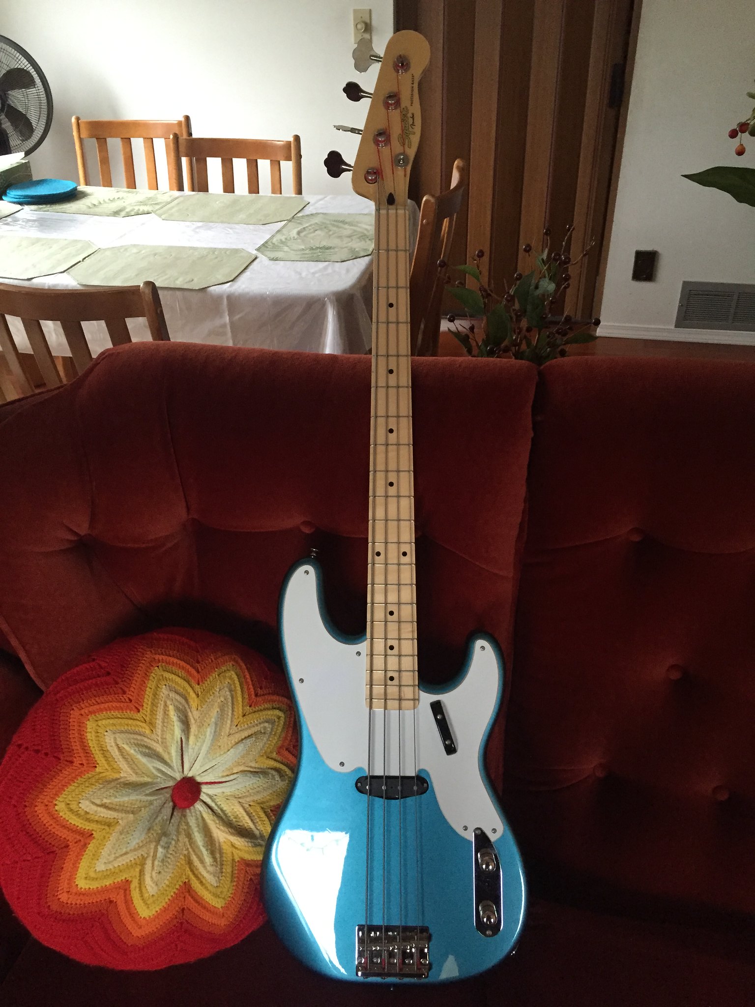
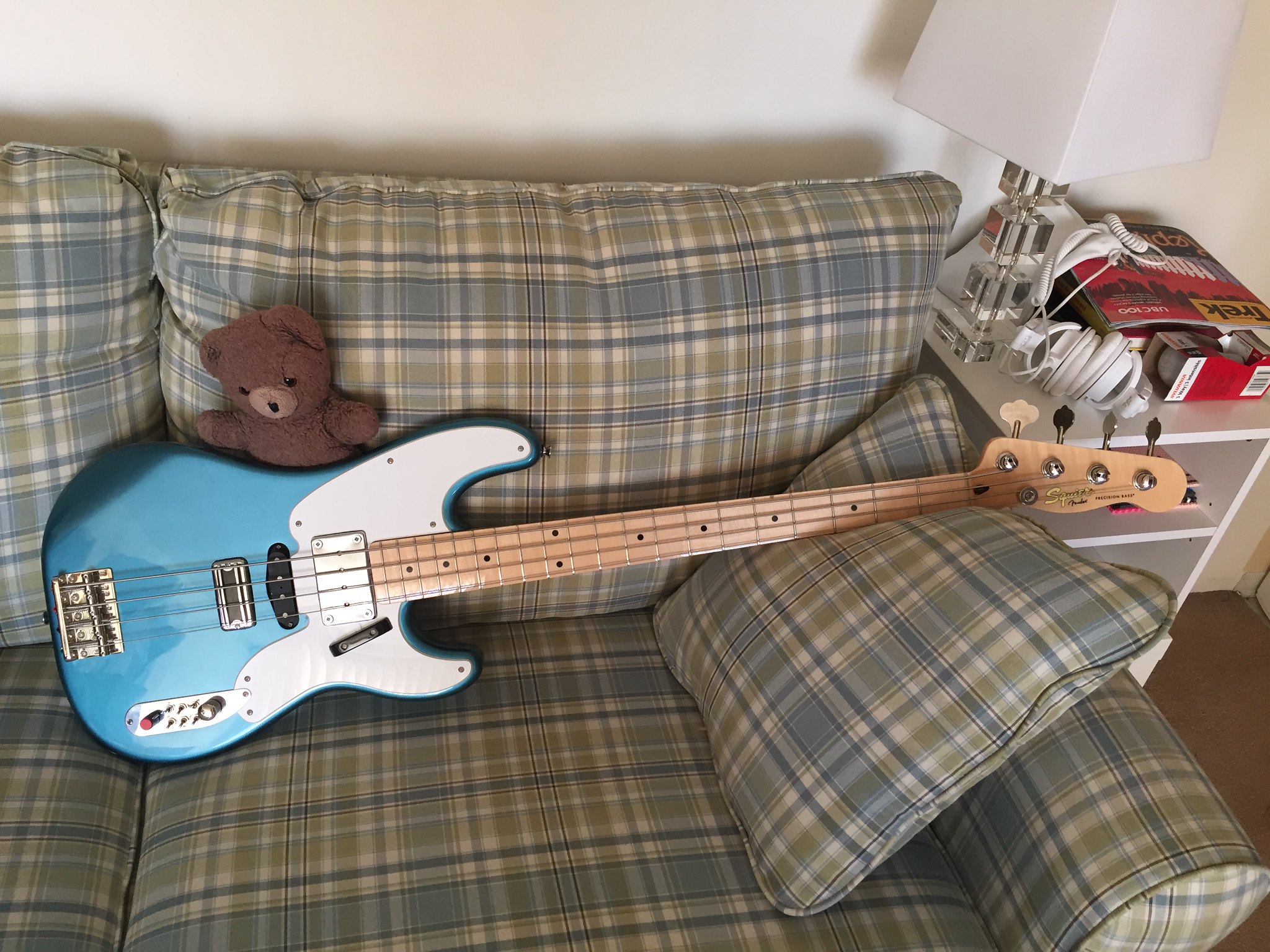
New bass day!  Well, "day" being used loosely, as the entire process has taken half a year.  I spotted this beauty on Boxing Day for $99:

IMG_2565 by dickolaswang, on Flickr

Single-coil Precision basses have never really been my thing, even though they look so cool, but I love the Squier Classic Vibe stuff so even with a few dings and dents $99 is an absolute no-brainer, if only just to flip on Craigslist.  I didn't buy it to flip, though, I bought it because I've had a two-year-long obsession with this bass:


So, I immediately started looking for a TV Jones ThunderBlade pickup.  Getting one was a slow process, because there weren't any TV Jones dealers in Vancouver.  One local shop was going to become one, but they had a lot of trouble properly closing the deal with TV Jones.  In the end it took three months to get the pickup.

I thought I'd also try and add a mudbucker in the neck position like the 70s Telecaster Basses because I've always liked that big deep sound, especially when playing with a pick.  I opted for an Artec mudbucker instead of a Fender Wide-Range humbucker, because when you think mudbucker, you think Gibson, not Fender.  They're dirt cheap on eBay -- I think this one goes for under $50USD (which unfortunately translated to something like $80CDN -- the Canadian dollar sucks right now).  There are two varieties, one with ceramic magnets and one with alnico magnets.  I opted for the alnico version, because I thought the ceramic one might be overwhelming.

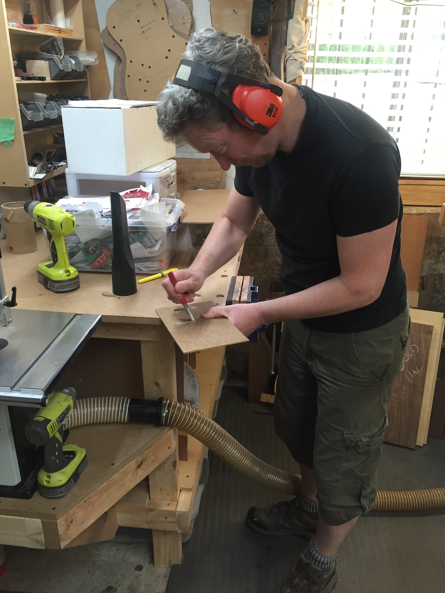
Once I finally got both pickups, I needed some woodwork done, so I called on my friend Ed Bond, of Halcyon Guitars (http://www.halcyonguitars.com/).  He's a busy guy, but eventually he was able to squeeze me into his schedule.

IMG_2733 by dickolaswang, on Flickr

Ed was the production manager of the Vancouver Larrivee factory for something like 14 years, and he makes stripped-down but amazing sounding acoustics under the Halcyon brand.  I have two of his acoustics.  He's a great guy to work with and makes an awesome product.  Unshown here: Ed filled a big distracting dent on the neck with some Crazy Glue so it's no longer a distraction while you're playing.

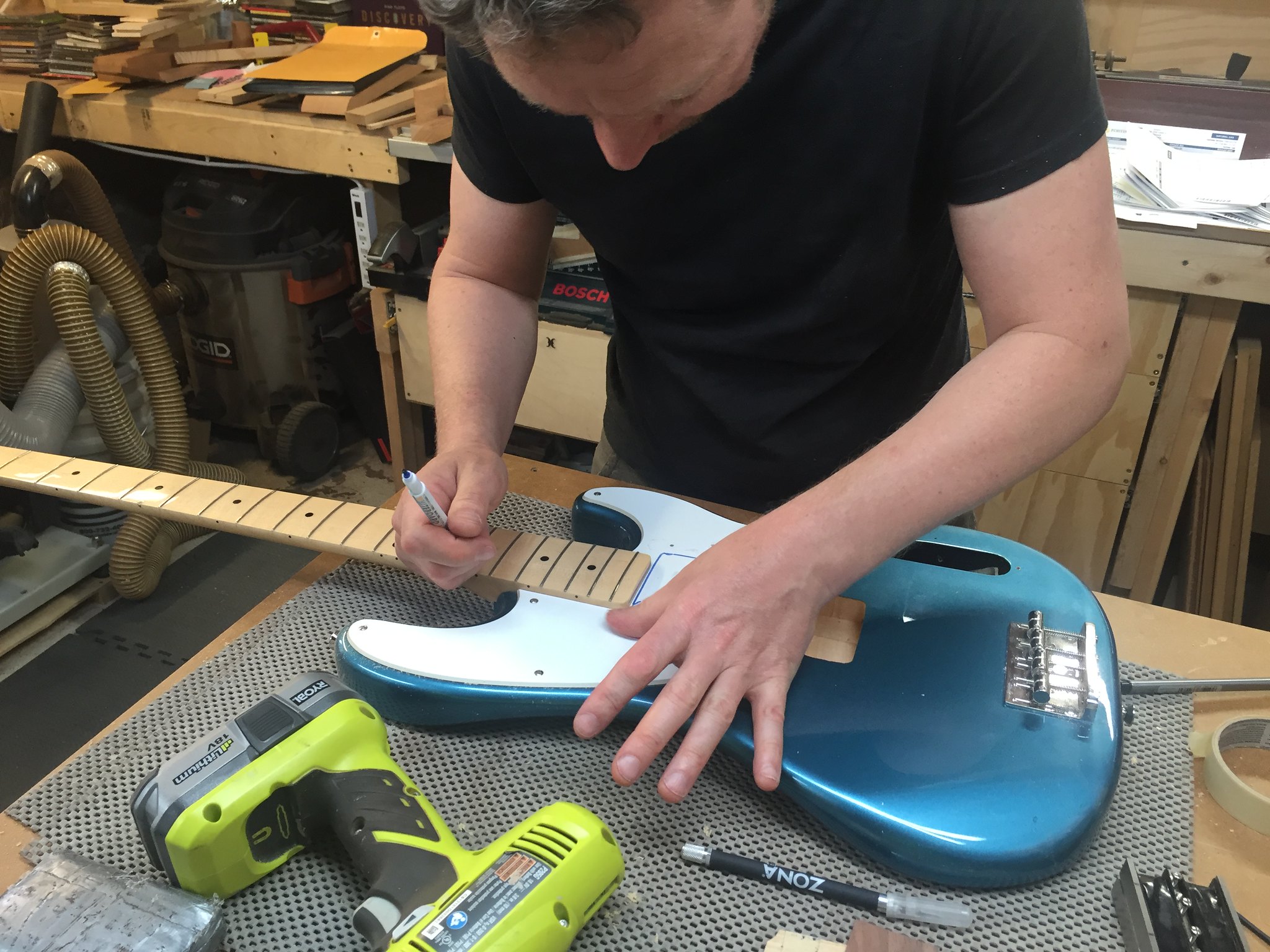
IMG_2734 by dickolaswang, on Flickr

There's one of his Halcyon headstock faceplates, here being used as a thickness gauge.

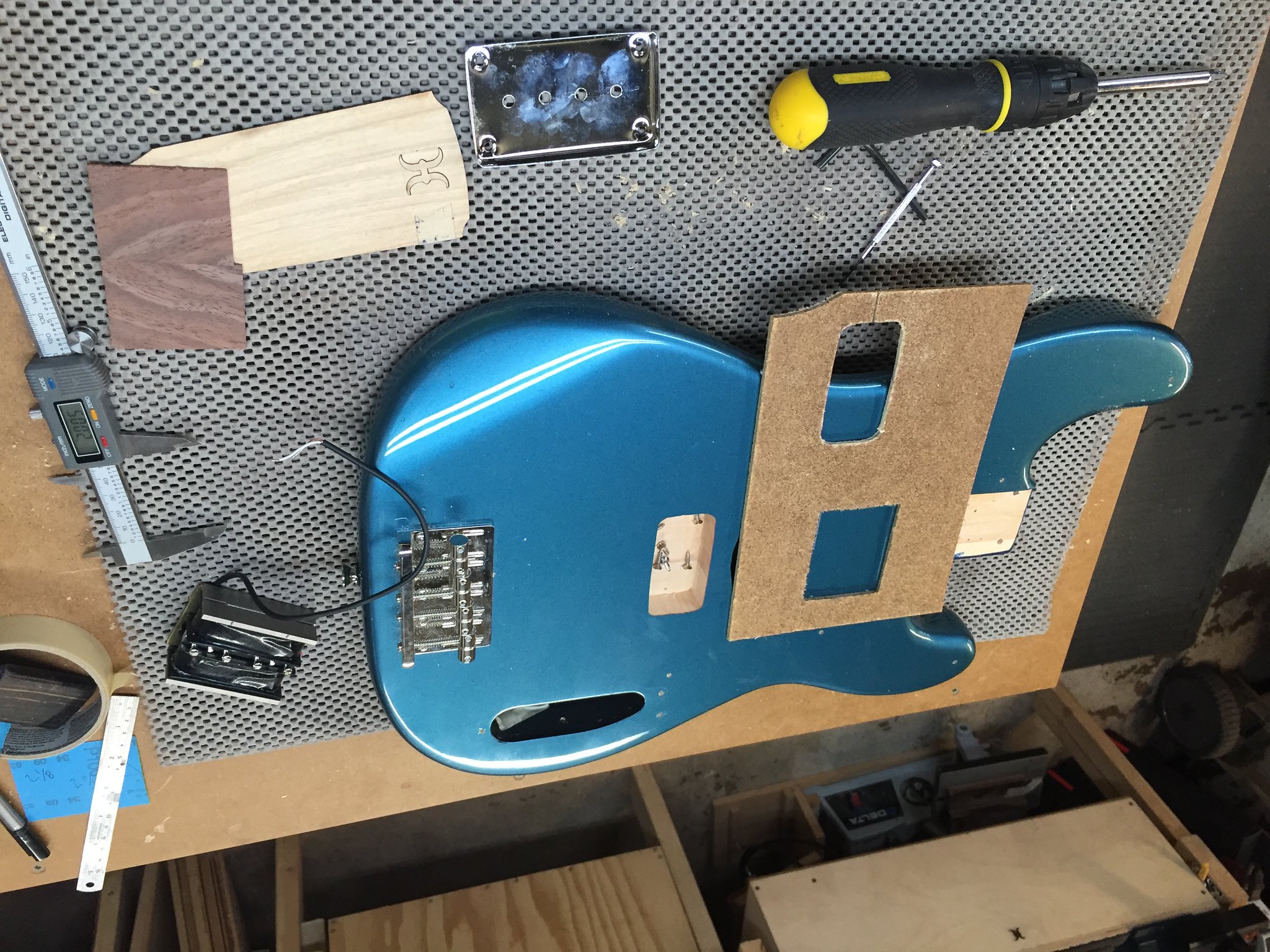
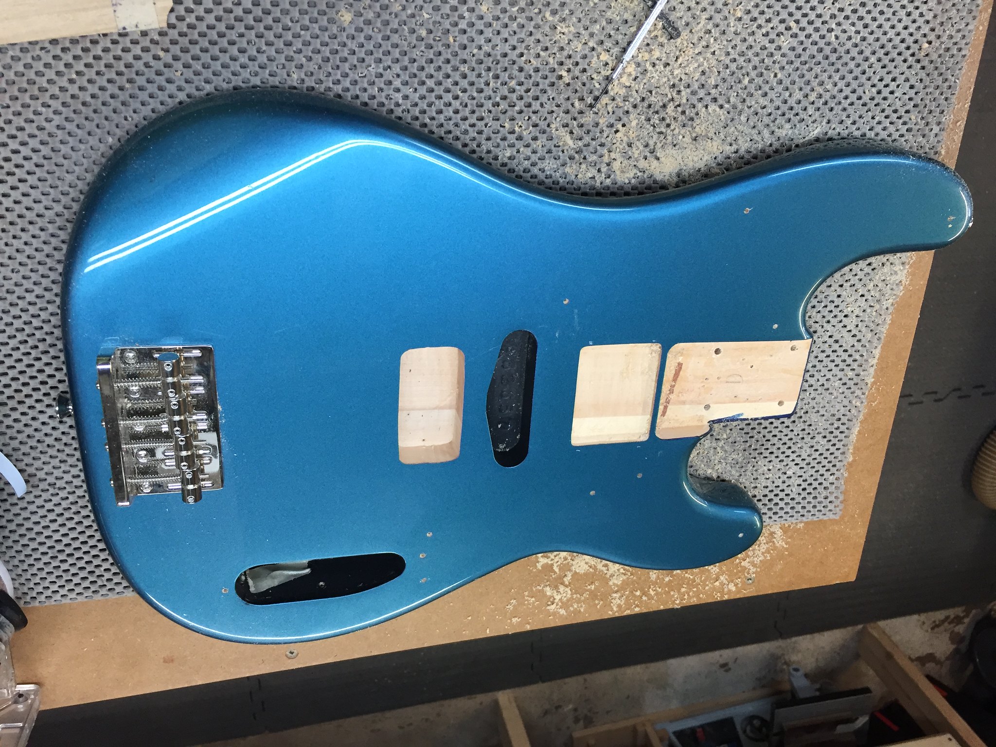
IMG_2735 by dickolaswang, on Flickr

Mudbucker mounting is weird: the pickup itself doesn't screw into the body, it just sits in the cavity, held in place by the cover.  Height adjustment is generally done with shims.  The cover is quite tall, so we had to mount the cover flush to the body to keep it from interfering with the strings.

IMG_2736 by dickolaswang, on Flickr

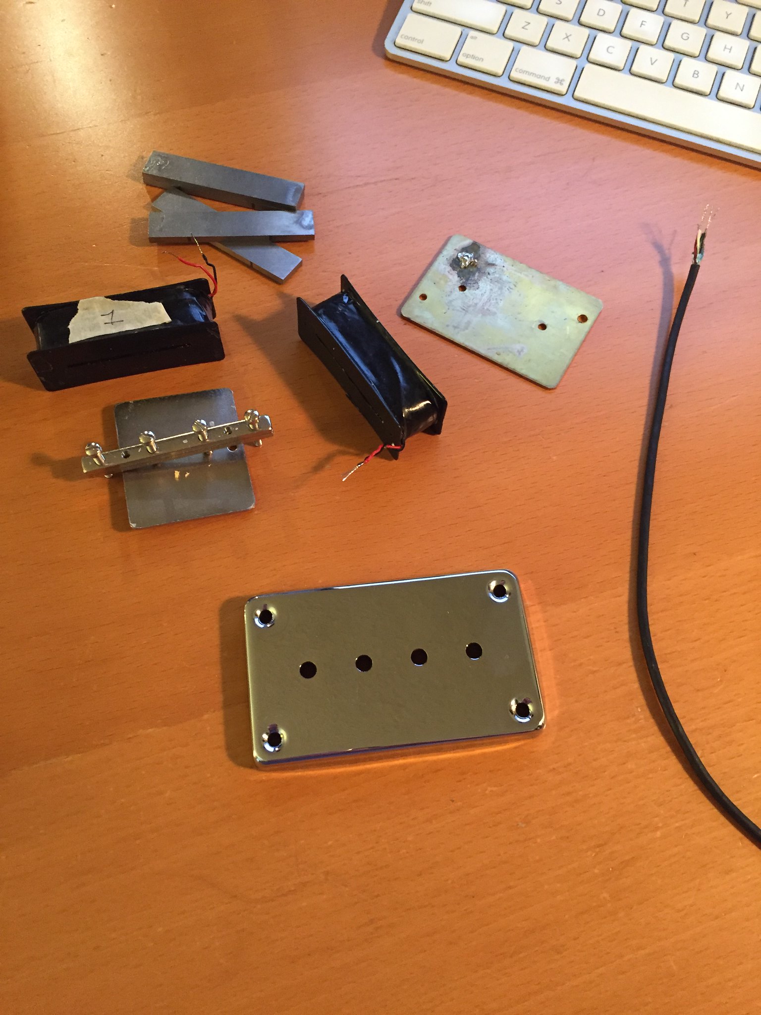
With the body all done, it was time for the wiring.  I wanted to be able to coil tap the mudbucker and/or wire it in parallel, but it comes stock with one-conductor cable, so I disassembled it and modded it with four-conductor cable.  Good thing I did, too, because the pickup was actually wired wrong internally: the coils were wired out of phase!  You get what you pay for, I guess.

IMG_2747 by dickolaswang, on Flickr

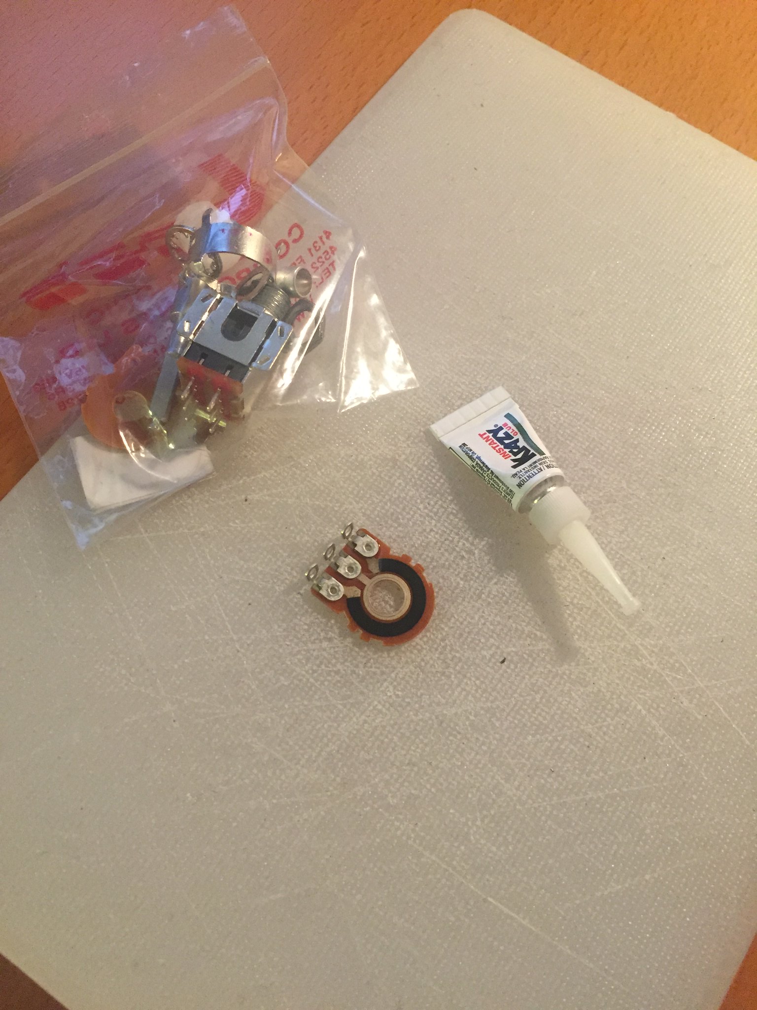
Next, a no-load tone pot.  I do this with a dab of Krazy Glue on the copper part of the outside track connected to pin 3 of the pot.

IMG_2748 by dickolaswang, on Flickr

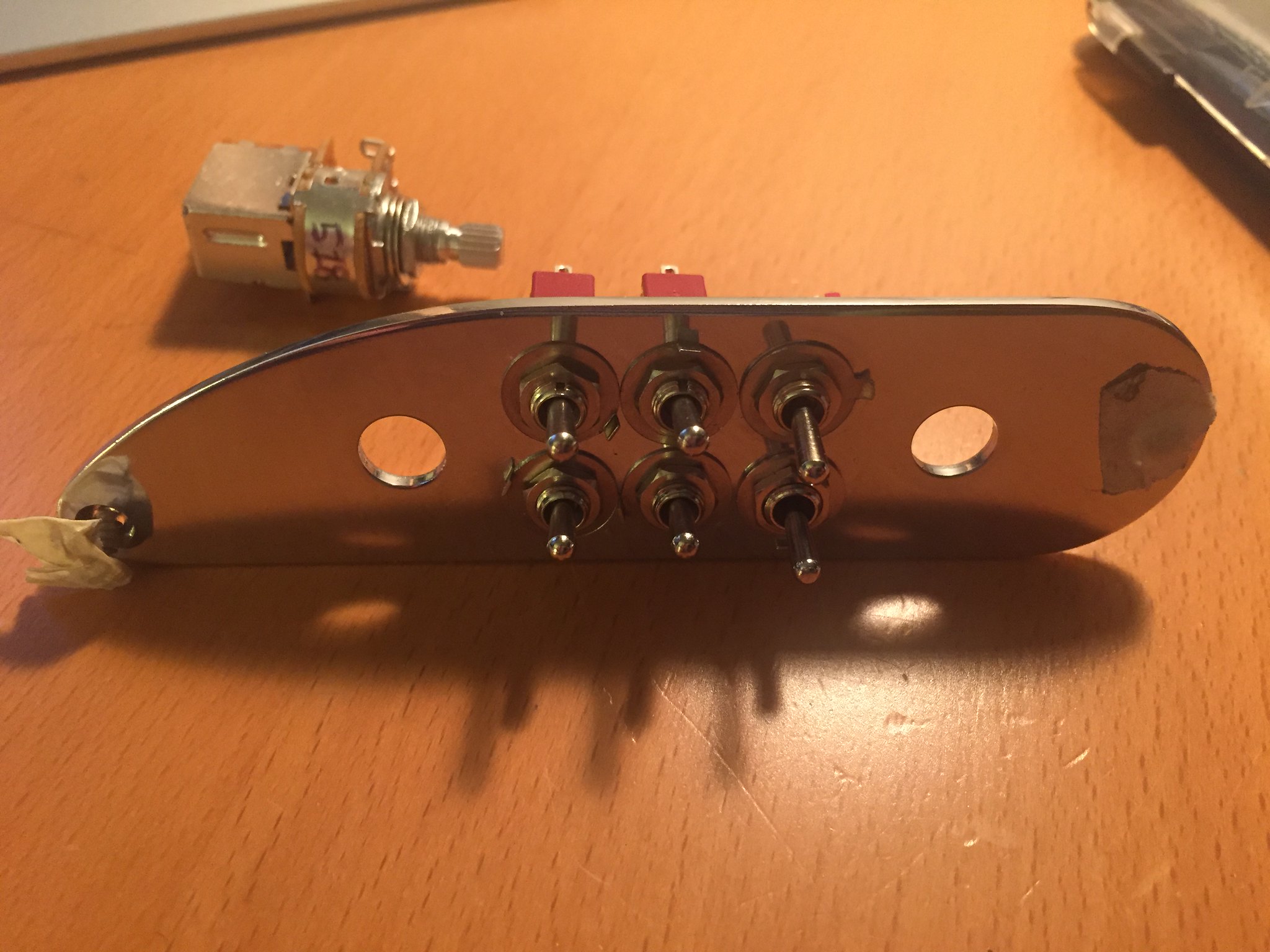
To implement the coil splitting and parallel wiring, I used the volume push-pull switch and one SPDT toggle to implement Seymour Duncan Triple-Shot-type switching on the mudbucker.  This way you can get the regular series wiring, or parallel wiring, or each coil on its own.  I did the same using the tone push-pull switch and another SPDT toggle for the ThunderBlade.

Even though I envision this bass more as three single-pickup basses than as a three-pickup bass, one way or another I needed a pickup selector.  I figured it'd be easier to drill three holes for toggle switches than to cut a straight opening to suit a Strat-style 5-way switch.  Given that it was going to take three toggle switches anyway, I opted for Dan Armstrong Super-Strat wiring, which uses two DPDTs and an on-on-on DPDT to give twelve combinations of the three pickups, including several settings with the pickups combined in series.  I'm hoping to find some series combination of the original single-coil pickup and one of the coils in the TV Jones pickup that will sound like a regular split-coil Precision.

The last toggle switch bypasses the volume pot.  It isn't a straight blow switch: it lifts pin 1 of the volume pot from ground, so that when the volume is turned all the way up, it doesn't load the signal at all.  It's just a little easier to wire.  I like to have the volume bypass and no-load tone pot for recording: in my mind, you're getting the purest possible signal recorded, allowing better tweakability after the fact.

IMG_2749 by dickolaswang, on Flickr

And at last, the finished product, in the hands of my favourite bass player:

IMG_2780 by dickolaswang, on Flickr

Well, almost finished.  I want to replace the tone knob with a better-looking one, as the stock ones are meant for knurled-shaft pots and my tone pot has a solid shaft.  More frustratingly, the TV Jones pickup that I waited two months for is actually defective.  It came with four-conductor wiring, but somehow two of the connections are shorted internally somehow.  This means my switching doesn't work quite yet, so I'm still waiting to see if I can find any useful settings that combine one of the coils with the middle pickup.  The normal series mode works fine, at least, and it gives me the tone I was looking for: lean and powerful but not muddy.

The mudbucker is wild!  I've never used anything like it before.  It's almost overwhelmingly hot and, well, muddy.  I think maybe I should have gone with the ceramics to brighten up the tone a little bit.  It definitely delivers on its promises, though, and sounds great picked.  The coil splitting and parallel wiring were a good call.  It's much less dark and produces a lot more growl in these settings, especially in parallel mode.  It doesn't play that well with the other pickups, because it's so hot (wound to 30k!) that when it's combined in parallel with either of the other pickups, it gets almost totally dominated by them.  Also, I can't imagine you'd ever want to put it in series with anything else, as it's so loud and so dark already that you'd just be getting pure sludge.  What might have been a better use of resources would be to use a stereo output jack and wire the mudbucker up to its own output, for use as a "subwoofer".

I'm really excited that after a long wait I finally have the bass I've been fantasizing about for two years, done my way.  Feels good!
#3
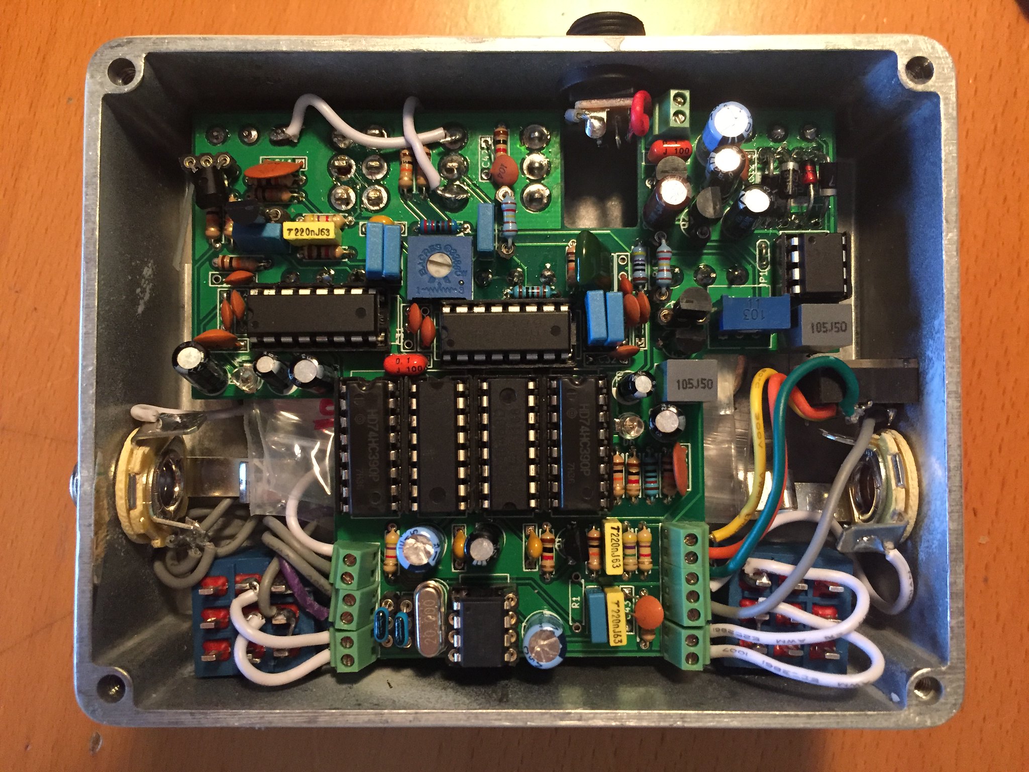
I decided that it was finally time to tackle The Big Boy, the chorus pedal I've been curious about since I was 15 years old and reading Guitar Player magazine: the Boss DC-2.  I've got it working on my breadboard, but I hoped someone out there would be kind enough to explain how the clock circuits feeding the BBDs work.

I've been working from the schematic that's floating around out there (http://www.freeinfosociety.com/electronics/schemview.php?id=123), substituting BL3207s and BL3102s for the BBDs and clocks.  I'm using TL072s for all the op amps, and BC327s for the PNP transistors in the clocks.  Once I sorted out some small issues, it made sounds, but those sounds were awful noises.  Poking around with my scope, it appeared that the problem was that the clock wasn't producing a usable pulse to feed the BBD.  By dumb luck, I decided to probe the signal fed to pin 7 of one of the BL3102s while the other one was connected to one of its outputs, and all of a sudden the output pulse was nice and clean.  Figuring it must be the parasitic capacitance of the probe, I added small capacitances to ground from pin 7 of both BL3102s and now it works.

So, my question to you is: why??  What did this do?  How does the clock work at all?  I'll break down some of my questions into point form, referencing parts by their numbering on the above linked schematic, and focusing on a single delay line, IC9.

- I get that op amp 6b feeds an attenuated copy of the LFO signal to the non-inverting input of 6a.  I *think* that Q8 forms a current source, that charges the 100p capacitor I guess?

- Probing the output of 6a, I see that it produces a triangle wave of constant absolute slope (i.e. positive and then negative with the same amplitude) but with wavelength and amplitude changing according to the LFO signal.  I didn't understand why the op amp's output could be anything but square, as it looks like it's wired up to work like a comparator, but am I correct in guessing that, by feeding the output of 6a into the oscillating circuitry of the BL3102 and back out through some other stuff into the inverting input, there is somehow negative feedback occurring here?

- Moreover, the triangle wave coming out of 6a doesn't go very high or low.  The datasheet of the MN3102 (I can't read the full datasheet of the BL3102 as it's in Chinese) says that the input to pin 7 registers high as a signal between Vdd-1 and Vdd, and low as a signal between 0V and 1V.  The triangle wave doesn't span this range, so how is it driving pin 7?

- Lastly, what did adding the small capacitance to ground at pin 7 do?  Why does it magically work now?

Any and all help is welcomed.  I didn't find anyone doing a real circuit explanation/analysis of this in any of my Googling, so whatever you can provide is greatly appreciated.
#4
Introductions / Greetings again from Vancouver, BC
February 16, 2016, 06:46:32 PM
My original introduction thread got wiped in the server crash.  I'm Richard and I'm from Vancouver, BC.  I got started building pedals about a year and a half ago, after I ran out of guitars to rewire, and I haven't looked back.  This forum has been a huge help to me and I've really enjoyed using the project documents.  I like to start from scratch and create my own layouts, but I usually start from a Madbean schematic.  I've built a Kingslayer, a Sunking, a NomNom, a Current Lover, a Collosalus, an Afterlife, a Cupcake, a couple of Mudbunnies (Mudbunnys?), and a Retrograde.

My original introduction got some replies from other Vancouver/Canada/nearby people.  Hoping to get some replies from them again!  Maybe we should get a Vancouver meetup going sometime.
#5
I posted about this before it was boxed, but the thread got wiped when the server problems struck.  I wanted to try my hand at Jon Patton's Hamlet Delay because his demos sound great and the circuit looked nice, simple, and elegant, but with some added bells and whistles: tap tempo, two PT2399s for extra delay, and an effects loop.  I bought a Taptation chip for the tap tempo, but when I did a little more research into how it works, I found that it isn't an ideal situation if you wanted to double up on the PT2399s.  A little more digging through forums revealed several helpful posts (particularly this one http://www.diystompboxes.com/smfforum/index.php?topic=94484.30) suggesting that a PLL would be a good way to get two PT2399s to sync without heterodyning.  There were also suggestions that this approach could be used to implement the tap tempo as well.

I then decided to finally try my hand at some Arduino programming, and after a bit of trying to get the uC to work as a tap-tempo oscillator and PLL, decided that it wasn't going to be fast enough to do both, so I programmed it to be a straight tap-tempo oscillator and turned to a CD4046 for the PLL duties.  This was fun!  I studied computer science but had never made anything that actually controls a real world machine -- closest thing I'd ever done was make two computers talk to each other, and that's kind of cheating :))

Anyway, this is what I ended up with:

IMG_2574 by dickolaswang, on Flickr

IMG_2573 by dickolaswang, on Flickr

and this is how it looks in context:

IMG_2613 by dickolaswang, on Flickr

IMG_2612 by dickolaswang, on Flickr

(My middle name is Hwa.)

I learned a lot from Rod Elliott's page too (http://sound.westhost.com/project26a.htm).  The secondary PT2399 stage is based on his Super-Simple PT2399 Delay Circuit, figure 3 on that page.  I tried to go light on the filtering on that stage, as I thought the filtering on the primary stage would handle the noise (the secondary stage actually precedes the primary one).  It almost does, but when the secondary PT2399 is engaged it definitely sounds a little gritty/distorted.  I should try a different PT2399 in that spot to see if it helps, but I can live with it, and I probably won't need the extra delay time much anyway.

I had a few issues putting it together: I fried one of the switches so it had to be replaced (which is a mean feat without desoldering braid, which I bought and promptly lost).  One of the pots was bad, too, so it had to go.  In replacing both of those things, I broke another trace on the board -- to go with the one I broke originally assembling the board -- so there are two ugly white jumpers on the finished product.  I also made a mistake on the board. I grounded pin 5 on the uC because I didn't fully understand the datasheet and thought it was an input pin.  Turns out that it can be an input if you futz around with the firmware, but by default it's a reset pin.  Next time I build it I will cut the appropriate trace, but in the meantime I lifted the pin by fashioning a 7-pin socket out of SIP sockets.

Nonetheless, it now works, and I'm still kind of blown away that I managed to get this project finished and functional!  Still gotta work on those EnviroTex and painting skills :P
#6
I've been spending the last two weeks learning to use KiCad and making a Collosalus layout (with several mods of my own).  Upon uploading to Seeed Studio, it asks whether I'd like to make the project public and I said yes, but then I realized that maybe I should have checked first whether this was kosher or not.  Is this cool?
#7
I've been looking at building an AMZ Mosfet Booster as a nice simple break from struggling with flangers, which led me to take a look at Jon's Bearhug FET Compressor.  (Why make *just* a booster if you can build a compressor and get the booster for free?)

I took a closer look at the Bearhug schematic and I have a question about D4, in the rectifier section (working from the schematic at this thread http://www.madbeanpedals.com/forum/index.php?topic=6802.0.  Is it necessary?  It just goes straight to ground.  Without it, you'd have half-wave rectification similar to that in the Orange Squeezer, but with it... what's different?
#8
I'm interested to try building a Zero Point SDX 2 but the boards aren't out yet.  I'd like to study the schematic beforehand because I'm a dork (and I might like to breadboard it first).  Is it possible to see the build document before the board comes out?  Even just a draft would be helpful.
#9
General Questions / Control voltage standards?
April 10, 2015, 05:11:40 PM
I'm thinking about building a dedicated LFO for use with control voltage inputs on pedals.  In particular, I have a TAPLFO chip that I'd like to box up into a module that I could use with other pedals like flangers, tremolos, phasers, etc.  I'm just wondering what is the "standard", if there is one, for control voltages in synths/etc.  A friend of mine says that it's 0-5V on his Korg synth; the TAPLFO datasheet gives a circuit for a -5V to 5V output.  Anyone else have suggestions?
#10
Build Reports / Current Lover on perfboard plus
March 26, 2015, 01:28:21 AM
Everyone's builds look so good!  Mine look terrible as I'm still getting the hang of all of the drilling/painting/labelling.  Still, thought I'd share some pictures of my last build: a modded Current Lover on perfboard plus.

I like to build using perfboard because a) I'm trying to learn as much as I can b) it gives me as much flexibility as possible to implement mods.  For the last 6 or 7 builds I've done, I've been using copper tape to make traces on the back.  It's served me well, but I think it might be time to look at etching my own boards soon!

The plan is to eventually build a matching Collosalus to play with TZF, hence the effects loop.  I borrowed the circuit for the stereo output from the BYOC Analog Flanger: I buffered the output of the Current Lover and fed that into an inverting op amp stage for the R output (the L output is tapped from the buffer directly).  I used the other half of that op amp to invert the phase of the signal going into the BBD, so I can switch between additive and subtractive flanging.  The last major mod was a primitive "manual" control, which is just an external pot in series with the clock trimmer.  Turning this up moves the sound from flange-y to chorus-y (and it totally whacks out the sweep, so, you know, not perfect).

Painting remains a real challenge.  I've had the paint wrinkle on me multiple times.  I'm probably putting too thick of a layer of paint on under the clear coat, and not giving it enough time -- the 48h it says on the can is not cutting it!  I'm not hugely enthused by either Krylon or Rustoleum clear coat anyway, as they're both pretty soft, so I might just abandon it altogether in favour of EnviroTex Lite.  The labels are just printable Avery clear labels, and I was too cheap/lazy to buy the full-sheet labels for a prototype build, so I just used a couple of the 2"x4" labels.  Glad I did, too, since the paint wrinkled so much.
#11
I'm planning to build a Krankosaurus, but my local electronics shop is out of 9.1v Zener diodes.  Just wanted to check that I can happily substitute 8.2v Zeners into their positions.  Do I ever need to worry about that being a factor when using any typical guitars/pedals?
#12
I've got a Kingslayer 2 on my breadboard right now (sounds great!) and I have a question about C10 in the schematic.  It calls for a 1uF tantalum (the notes in the original Kingslayer document say an electrolytic works fine here, which is what I have), but the positive side of the capacitor is referenced to ground.  Why use a polarized capacitor here?

That said, it does seem to work.  I tried replacing it with a 1uF film capacitor and it sounded more or less the same (well actually the film capacitor does seem to give it a little beefier tone, but I'm not sure I could really put my finger on it nor could I be sure my ears aren't just playing tricks on me).
#13
I've been doing all of my builds on perfboard and have always placed my wires on the component side of the board.  However, I've started using better quality perfboard that is plated through hole, and it strikes me that I should be taking advantage of this and attaching my wires to the "trace" side of the perfboard like a proper via.  What's the best way to do this?  It seems like soldering to the traces on the same side as the wire is a recipe for burnt wires, so is it best to run a short trace on the component side of the board in those spots and then solder the wire end to that?
#14
I've been corralling the parts to put together a Kingslayer.  My local go-to electronics shop only had the ICL7660 charge pump in stock, and I foolishly bought it before I knew the difference between it and the TC1044S/ICL7660S/MAX1044.  I've heard people warning that there will be a whining noise due to the 7660's oscillator frequency being within the audible spectrum.  Will I be able to get around this by adding an appropriate (say, 100uF, 25v) filtering capacitor across the -9v and +9v rails, or is the noise coming from somewhere other than the voltage ripple?
#15
Hi all,

I'm pretty new to building pedals and have been lurking around the forum for a while taking stuff in.  I got started through the DIY club on tonefiend.com and have built all five of the entry level projects (Electra distortion, Bazz Fuss, FET clean boost, Rangemaster, Fuzz Face), and have just finished building a five-knob Orange Squeezer, with mods lifted from Mark Hammer's Tangerine Peeler and GGBB's Orange Smoothie, and with some advice/explanation from Mark Hammer via personal message.

Next up on the docket, and currently on the breadboard, is an Afterlife/Flatline; actually, it's a Ghost Note, as I copied Jon Patton's threshold control mod.  Because I'm a sucker for punishment, and because I'm trying to learn all I can from each circuit, I'm attempting to make a five-knob version, trying to figure out what I can do to adjust attack and release.  The Afterlife already includes a "sustain" control but it seems to me that that's really a ratio control.  Jon kindly answered some of my questions via personal message and suggested the following:


  • replace R6 with a small-valued pot to adjust the attack
  • add a 1M pot (plus series resistance) across C3 to shorten release

I replaced R6 with a 1K trimmer, and it seems quite effective.  I haven't tried #2 yet, but I did try adding a trimmer in series with vact_1A (the LED) to lengthen the decay, and it seems to work.  Jon mentioned that the release in the Afterlife is already quite long, but I've noticed that the LED pretty much instantly turns on and off (I don't have a Vactrol so I rolled my own with shrink tubing, an LED, and an LDR, which allowed me to see how bright different types of LED got before they went into the shrink tubing) unless I turn the trimmer up, and the release feels pretty quick to me unless I do that.  In fact, I can't really tell any visual difference in the behaviour of the LED if I just straight-up remove C3 from the circuit.  The LED still just lights up when I play and turns off when I don't.  Thus, my questions:

1) If I'm not misunderstanding the circuit, R6 controls how hard the signal gets "pumped" to C3, much as the 1k5 resistor before the diode in the Orange Squeezer controls the attack in that circuit.  But, that's also what adjusting the gain of IC1_B does (i.e. Jon's threshold control), albeit from "the other side" of the signal.  So, are the effects of these adjustments completely conflated, or do they actually have any distinct effects?  It does seem to me that adjusting R6 changes the attack while changing R7 adjusts the threshold, anyway, but I would need to fiddle around with it more to try and identify if they're doing the same thing.

2) Should I be worried that there is by default no resistance protecting the LED?  I'm not sure of the kinds of voltages we're feeding the LED, but from my rudimentary knowledge of diodes and Kirchhoff's laws, I don't quite follow why we don't see an unbounded current across the LED when the voltage of C3 exceeds Fv.  Moreover it seems like C3 is either instantly dissipating its charge across the LED if I don't put in the series resistance, or just not doing anything.

As a side note, I found that I'm getting really good results (i.e. strong compression) using what I think is an MEC MLG5547 LDR (http://leeselectronic.com/index.php?id_product=7363&controller=product&search_query=photo+resistor&results=11).  I started off with an old LDR (marked NSL-32 CANADA, if that means anything to anyone) that I got from a friend, and thought "really subtle effect, can't quite tell if it's on but it seems nice" but then when I tried the MLG5547 it clamped down really hard.  I can't compare it to a Vactrol VTL5C3 but the datasheet tells me that its turn on time and turn off time are pretty snappy (20ms and 30ms respectively), and its light and dark resistances are in the same realm as the VTL5C3.  So don't lose hope if you're rolling your own!  Actually, that brings me to another question:

3) The datasheet says I should be using a green LED, but my green LEDs aren't even close to as bright as my orange ones, so I'm getting better results with an orange one.  I looked it up and saw that green LEDs have a very wide range for Fv; does that mean that their turn-on voltage also varies?  Should I shop around for a brighter green LED?

Apologies if these questions have been addressed somewhere that I haven't already looked!