I've also been playing a lot of CS2 lately, and I have an addiction. The updated graphics and smooth gunplay make every match super engaging. I've been grinding ranked matches with friends, and it's honestly some of the most intense gaming sessions I've had in a while. The strategy and teamwork are interesting, especially during those close overtime rounds.
- Welcome to madbeanpedals::forum.
This section allows you to view all posts made by this member. Note that you can only see posts made in areas you currently have access to.
#2
Open Discussion / Re: Video Maker Software?
January 22, 2025, 01:13:09 PM
DaVinci Resolve is fantastic for advanced editing, with great tools for color correction and audio. HitFilm Express is another good choice, especially if you want to add effects. For something simpler but still capable, Shotcut is user-friendly and covers the basics well.
If you're working with audio files for your demo and need to convert them to different formats, this tool could be handy: https://www.movavi.com/audio-converter/aif-converter.html. Good luck with your video—sounds like it'll be a fun project!
If you're working with audio files for your demo and need to convert them to different formats, this tool could be handy: https://www.movavi.com/audio-converter/aif-converter.html. Good luck with your video—sounds like it'll be a fun project!
#3
Open Discussion / Re: What are you playing? (games)
January 10, 2025, 11:11:45 AM
Your recs are solid, Rocket League is such a fun mix of chaos and skill, and I totally get the frustration when things don't go your way. Insurgency is another great pick; the sound design really does add a whole new level of intensity.
If you're into multiplayer games with unique styles, you might enjoy Team Fortress 2. It's got that perfect mix of humor and strategy, and it's still surprisingly active after all these years. The TF2 player count shows just how strong the community is even now. For something a bit more chill but still engaging, I've also been playing Hades, it's an absolute gem if you haven't tried it yet.
If you're into multiplayer games with unique styles, you might enjoy Team Fortress 2. It's got that perfect mix of humor and strategy, and it's still surprisingly active after all these years. The TF2 player count shows just how strong the community is even now. For something a bit more chill but still engaging, I've also been playing Hades, it's an absolute gem if you haven't tried it yet.
#4
General Questions / Re: Anyone have a pre-2015 Lowrider PCB for sale?
March 16, 2016, 12:49:35 AM
You guys rock...got a couple of PM's and have some options....great!
Warren
Warren
#5
General Questions / Anyone have a pre-2015 Lowrider PCB for sale?
March 15, 2016, 05:48:38 PM
Hi,
I'm looking for a pre-2015 version of the Lowrider PCB. I absolutely love the pedal, and I've got a friend that wants one. I built the 2015 version, but we both much prefer the older version.
Anyone?
Thanks,
Warren
I'm looking for a pre-2015 version of the Lowrider PCB. I absolutely love the pedal, and I've got a friend that wants one. I built the 2015 version, but we both much prefer the older version.
Anyone?
Thanks,
Warren
#6
General Questions / Re: Where are you guys buying enclosures?
February 08, 2016, 06:57:55 PM
+1 to Pedal Parts Plus. Worth the slight extra cost to me due to high quality and really fast shipping, regardless of what color I've ordered.
I've had some issues as others with Mammoth in the past, generally pretty good, but I've had several orders that took a month to ship, way beyond their posted lead times, and screws that weren't a great fit.
If you want cheap, Tayda, and of course Smallbear is great too, wish they did colors.
Warren
#7
Global Annoucements / Re: 2015 BOTY Contest Entry Re-post
January 23, 2016, 04:27:26 PM
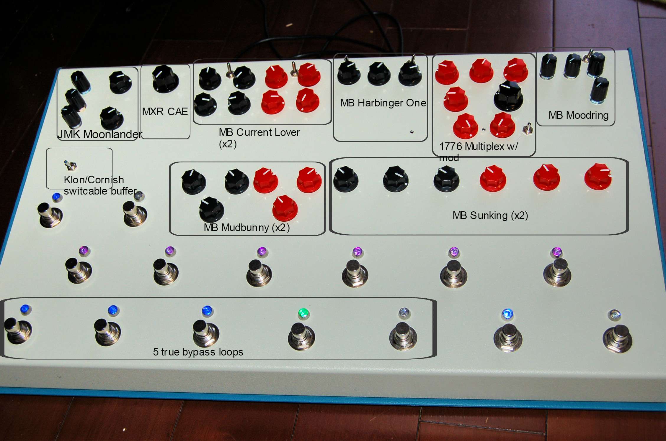
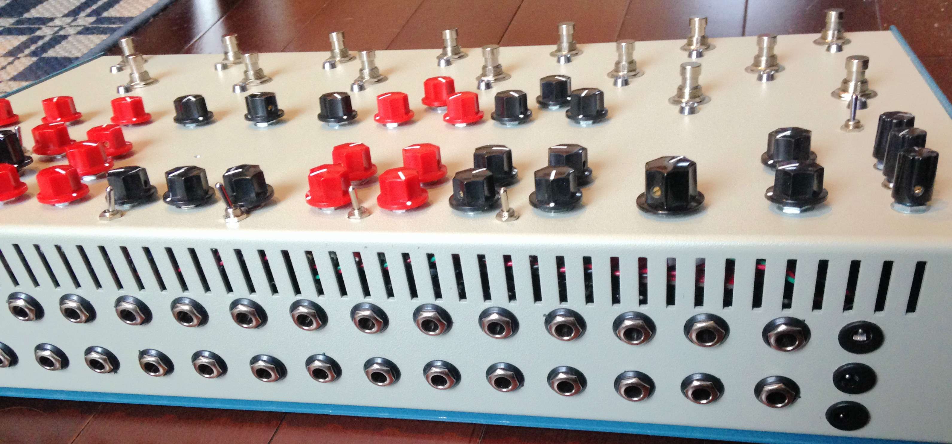
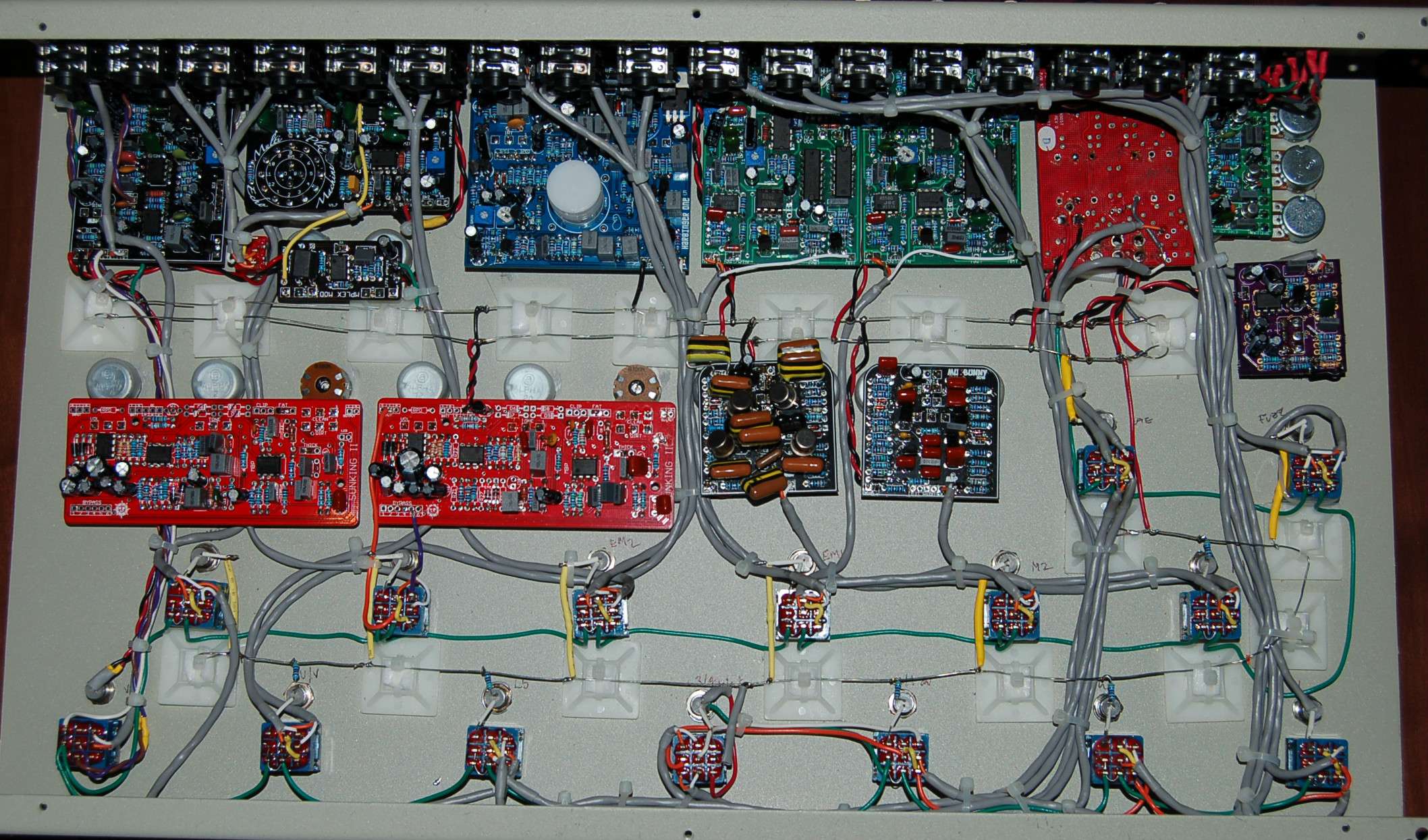
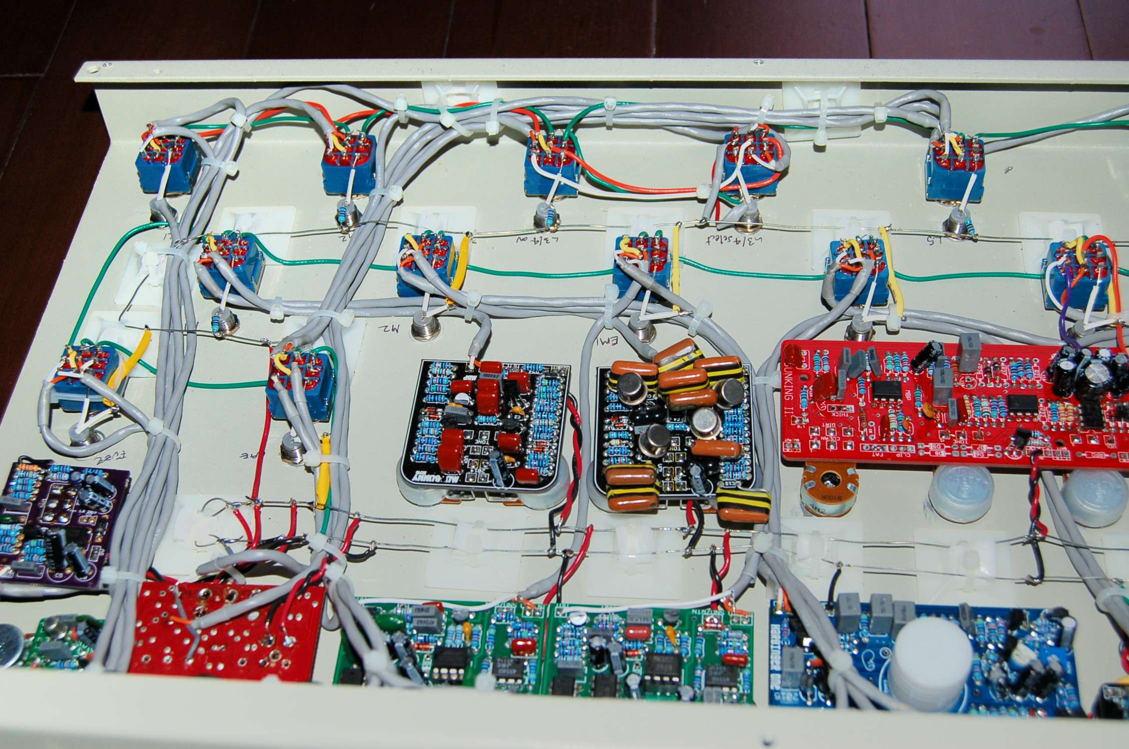
Here's some pics of the Floydian Slip....11 effect multi with built in 5 channel true bypass loops. A nightmare of wiring proportions!


and the soundclips are here:
https://soundcloud.com/user258480591/floydian
Enjoy!
Warren


and the soundclips are here:
https://soundcloud.com/user258480591/floydian
Enjoy!
Warren
#8
Global Annoucements / Re: BOTY - Winners Annoucement
January 23, 2016, 03:28:32 AM
Congrats to Lee, and all the other winners...amazing projects all. Incredible creativity, skill and good old fashioned gumption.
I'm going to take the lectric-fx credit. I'm a junky for flangers and phasers, and I gotta build that Bloodstone.
Thanks to Brian and all the other sponsors for their generous prize donations. I hope to post up some of my build pics again sometime, but just started a new job, so my time and mental capacity is limited right now...no chance I'll be attempting another mega-board anytime soon, although there are plans for another with all modulation fx someday.
Warren
#9
Global Annoucements / Re: Important: Read This, Please
January 19, 2016, 01:55:54 AM
This definitely sucks, I'm going to miss all the BOTY build posts, drooling over Lee's wiring, seeing those crazy cut off fingers on the Buzzsaw....
I think folks have posted the correct order for the winners...congrats to Lee, well deserved, and thanks for everyone that voted for my Floydian Slip. So many great builds.
Here's to a great 2016 of DIY, and restoring the lost knowledge, one post at a time.
Warren
I think folks have posted the correct order for the winners...congrats to Lee, well deserved, and thanks for everyone that voted for my Floydian Slip. So many great builds.
Here's to a great 2016 of DIY, and restoring the lost knowledge, one post at a time.
Warren
#10
Tech Help - Projects Page / Re: Dirtbag, very very distorted
April 29, 2012, 09:17:01 PM
Alright. I went through every single resistor, measured it and compared it's color code where it couldn't be measured accurately (due to a cap charging or a parallel resistance) and found it 100% correct. Now, being thoroughly perplexed, I decided to think out of the box a bit, and even though I'd done all the recommended mods and replaced R21 and C14 back to 1K, I put them both back to 100k. Dirtortion is now gone. Excellent, however, my signal is too weak now. So, I decided to put a 50k trim (all I had on hand) for R21, and now....voila, I can dial in just the right amount of signal until I get distortion.
I rebiased everything, and also replaced the feedback pot as Brian directed.
Long story short, it now sounds fantastic and works perfectly! I'm very happy with it.
So, thanks to Brian and Scruffie for the assistance. Whew, I now deserve a beer. Then after the beer, I can throw it into an enclosure!
Thanks a lot!
Warren
#11
Tech Help - Projects Page / Re: Dirtbag, very very distorted
April 16, 2012, 02:31:40 PM
Brian:
Yes, I'm using a 9V supply. I reverified the jumpers for the 3205 (correct) and R11 and R12 are definitely 47K. Perhaps the signal is too hot at pin 7 and it's just not as noticeable until the repeats and feedback enter the picture. It is pretty loud on pin 7. What sets the gain out of the compander?
Scruffie, the pin 2 & 6 of the BBD are almost exactly half supply so that seems fine, you're probably right about a bad value somewhere that's affecting the gain. Where should I start looking?
Thanks guys, I appreciate the help.
Warren
#12
Tech Help - Projects Page / Re: Dirtbag, very very distorted
April 15, 2012, 02:36:12 PM
Measured the clock with my DAW. 9.75kHz
#13
Tech Help - Projects Page / Re: Dirtbag, very very distorted
April 15, 2012, 12:24:38 AM
Some progress:
Adding another diode in series brought the voltage down to about 7.7. That helped a bit, in that now the bias setting is not on the extreme end of the trim, but closer to the centre. There is also less distortion, but it's still unusably bad. Another observation is that I have to have the feedback pot almost completely CCW, otherwise it self oscillates terribly, that's with both gain trims fully CCW. I can't bias it with the feedback half way, it's oscillating way too much and is a distorted mess.
I unfortunately don't have a scope to see the clock signal, my 4047 is a BE suffix, from TI. I do have a capacitance meter, and C41 is very close to 240pF, I made it with 2 caps in parallel to get it close. I'm going to try to rig up a signal to my DAW to get a reading of the clock signal.
Incidently, I happened to have another NE570, so for kicks I swapped it, it acts exactly the same.
#14
Tech Help - Projects Page / Re: Dirtbag, very very distorted
April 13, 2012, 09:39:55 PM
Hi Brian,
Pin 5: 8.4V
Pin8: 8.2V
Pin 7: 8.3V
with bias CCW: 8.3V
with bias CW: 0.6V
I've actually already swapped the BBD with some others I had, and it does exactly the same thing.
Thx
Warren
Pin 5: 8.4V
Pin8: 8.2V
Pin 7: 8.3V
with bias CCW: 8.3V
with bias CW: 0.6V
I've actually already swapped the BBD with some others I had, and it does exactly the same thing.
Thx
Warren
#15
Tech Help - Projects Page / Re: Dirtbag, very very distorted
April 13, 2012, 09:00:10 PM
Still no progress on this, but more to report. Essentially, the signal is getting to the first BBD IC4 pin 7 just fine, no distortion, however, when it comes out of pin 3 and 4 of the BBD, it is fizzy and brutally distorted. The only way I can get anything out of it is with the bias trim turned nearly completely CCW. There is a tiny amount of trim where I get sound out, otherwise it cuts out completely. Where can I start looking for problems?
Thx,
Warren
Thx,
Warren
