News:

Forum may be experiencing issues.

Main Menu
Menu

Show posts

This section allows you to view all posts made by this member. Note that you can only see posts made in areas you currently have access to.

Show posts Menu

Messages - MarcFive

#1
Tech Help - Projects Page / Re: Wah mod
April 12, 2015, 02:11:19 AM
Quote from: Bflat5 on April 11, 2015, 10:32:20 PM
I just rewired it following the fulltone mod and now there's no output switched on or off.

Did you use the same switch or did you check it? A picture of what you did would help. Did you trace the wiring to see if it was modded?
#2
Build Reports / Re: Liquid Gold...
April 10, 2015, 11:36:21 AM
Quote from: Coda-effects on April 09, 2015, 03:31:04 AM
First SMD? Really?  :o
I quit.

I'm out. Sheeesh.
#3
Tech Help - Projects Page / Re: Wah mod
April 10, 2015, 11:30:53 AM
Ya, that Fulltone link jball85 posted: http://www.fulltone.com/sites/default/files/manuals/fulltone-v847-mod.pdf

Would be my suggestion. That wiring you've got going on doesn't ground the board input when bypassed. But I don't know why it's whining when on. You may have gotten the switch too hot when soldering, that looks like a big glob of solder on one of those legs. In any case I'd scrap that wiring layout. It's hard to tell where the Black wire on Lug1 of your pot is going. To the output jack ring I would guess(?). It should also have a wire going to the switch from that lug for grounding like the Fulltone layout.

It might be a good idea to study a few layouts of the VOX wiring and see if someone has modded the pedal before to see if thats playing a role. I can't trace the wiring with your photo's.
#4

[/quote]

I take it you switched to a quad op amp with a higher voltage rating?
[/quote]

No, same ones. TC1044SPCA, TLC274. I also noticed whine with the gain all the way down. I've got parts coming for a couple more of these, I ought to be able to get one working and then have a reference. I'll have to order a different quad and see what that does. I didn't realize there was an issue, I built this one year ago and then health issues popped up , but I seam to be bouncing back.  So I missed all the discovery.
#5
Quote from: mgwhit on April 09, 2015, 07:24:36 PM
What value is your C9?  It should be 390pF, but it's the same size as your 390nF C5.  If you have a 390nF in C9 you're letting way too much signal bypass the negative feedback loop resistance, which would kill all of your gain.


And the winner is... OMG, do you know how many times I've gone through these... I seriously need to buy you a beer!
Well done.  ;D

Swapped the errant cap and nothing. Swapped the IC's and got gain finally  but glitchy when I'd dig in a little. Then it just started sputtering.  Gonna put it away now before someone gets hurt.
#6
Quote from: TGP39 on April 09, 2015, 02:42:42 PM
Hi Marc. To my knowledge, you can't measure a pot in circuit the same way you can't measure a resistor in circuit. Anyone, please correct me if I'm wrong.

Steve.

Well, if you look at the schematic of the dual gang pot the clean side has a parallel 1.5K resistor. This seems to be what my meter reads regardless of where the pot is adjusted to. It also has a resistor and cap in parallel but I think the cap pulls it out of the equation.

The dirt side of the pot doesn't have anything attached in parallel that isn't broken up by the op-amp, so it reads like it should read.

As far as measuring resistors, I find most can be read, but there is the odd circumstance where I've pulled a resistor only to find it was indeed just fine. In fact the only two bad resistors I've ever come across were in a Handmade Bluesbreaker pedal an old friend asked me to look at. The board was perf board and the wiring looked like a birds nest, I think he used enameled pickup wire or something. It was just dumb luck I figured out what was wrong. The only electronics I had engaged in up until that point was building a Pete Cornish buffer. Come to think of it, that's what started this whole mess, I didn't want to pay $800.00 for $3.50 worth of parts... Now I have come across some Carbon Comps that I believe were rejects, but thats another theory.

Caps seem to have a lot more happening, but I'll tend to check them before install since they vary so much.

I've only been doing this for a very short amount of time, but these are my observations.


#7
Quote from: mgwhit on April 09, 2015, 03:16:55 PM
Quote from: MarcFive on April 09, 2015, 03:06:30 PM
R29 feeds to R2 which feeds into IC1 pin3. Looks like R29 end @ IC3 pin8 is not soldered.

R29 does look dodgy, but it also feeds every point in the circuit that is receiving ~4.5V (VB).

Yep, I missed that fact. :o
#8
PM me, I'll mail you the resistor. NC
#9
That would explain the gain pot issue, but it wouldn't explain the weird voltage on IC1 pin3.  i would suggest reflowing the solder on that pin.  Can't tell if it's bad, but it's one of the few things that could explain an out-of-place voltage.  I checked all the resistors in that part of the circuit and they looked good.

R29 feeds to R2 which feeds into IC1 pin3. Looks like R29 end @ IC3 pin8 is not soldered.
#10
The solder on R29 looks suspicious from my house.
#11
Quote from: madbean on April 09, 2015, 05:17:24 AM
Like Steve said, the voltages are correct. The problem is that the IC is pushed a bit beyond it's capacity which is why I changed the limiting resistor as is seemed to solve the problem. But, an IC swap also accomplishes the same thing...the only difference is whether or not you feel one IC is better than the other. Personally, I really like the 274 in this circuit which is why I put it in the BOM even though the design pushes it just out of spec. But, the 2264 or 074 also sound fine.

Thanks Brian, Just on a hunch I slapped a waning battery on the pedal as opposed to my Voodoo Lab supply, but that didn't seem to help much. (Reasoning the 150R resistor was dropping the supply voltage a smidge).  I measured the dual gang pot on me Sunking II and it has the same sort of odd readings in circuit as this one. So I'll swap the resistor and report back.
#12
Quote from: TGP39 on April 09, 2015, 04:07:53 AM
Hi Marc. You are getting ~18volt swing on your quad.  The TC1044SCPA is taking in the 9 volts on pin 1 and pushing out 9 volts on pin 8 AND -9volts on pin 5.  There is your 18 volt differential.  I hope this helps.

Steve.

Thanks Steve, I thought that was the case, but I was using the Sunking II as a reference. So I guess the Sunking is running one TL072 @ 24v and one @ 12v(?). When I originally measured the Sunking, I got something close to 18v and figured I'd have the same sort of finding on the Kingslayer circuit. I had in my mind the pedals ran at 18v. I guess it's time to start deciphering some Data Sheets.
#13
Thanks Brian,

But I don't think we're on the same page. I see the 10R/150R change, but I thought I should be getting 18v somewhere in that quad. I'm not getting any gain/clipping or buffering. But if you think those readings are good, my only guess is the 100K dual gang, I don't get any resistance change on the clean side sweep .
#14
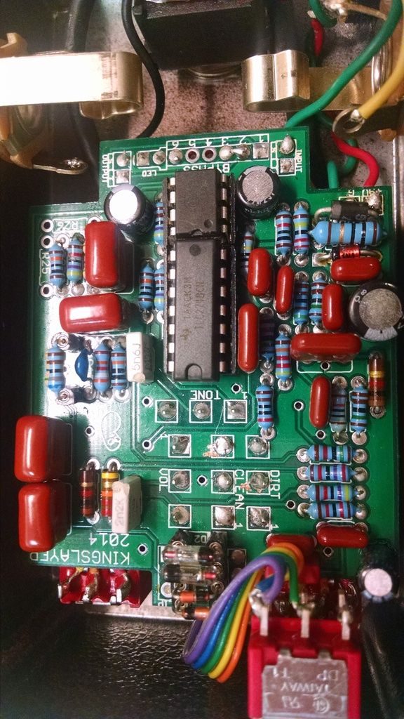
Came back to this after a year, because I just ordered parts to build this pedal for some friends, and I still haven't figured out what I did wrong with this one. I know I've checked every component value, even measured the components that allow being tested 'in circuit.' Just installed another set of chips.

Pedal turns on, tone control sounds awesome, volume works,(fooled me into boxing it), fat mod works, everything else, gain, bypass buffer, clipping switch is not functioning. The gain knob fully counter clockwise induces a little whine, otherwise has no effect.

1044 SCPA Voltages are as follows:

1. 8.75v          8. 8.71v
2. 5.05v          7. 5.24v
3. 0                6. 3.84v
4. -3.59v         5. -8.53v

TLC 274:

1. .4mv           14. -2.9mv
2. o                13. -.1mv
3. .1mv           12. -0
4. 8.84v          11. -8.58v
5. 0                10. -0
6. 0                  9. 0
7. .1mv             8. 3.0mv


I'm hoping these voltages just scream out at someone.


I had the board out of the box and went over the entire board with a loupe and hit anything that even looked  the slightest bit not perfect. I am suspicious of the dual gang pot, but I can't see how that would affect the tlc 274 voltages.
#15
I get frustrated and hit it with compressed air after the solder sucker. A little preventative tape and the vaporized solder should clean up with a toothbrush. But a de-soldering station? I likes the sound of that. I'm constantly finding new ways to solder stuff the wrong way. :-\