News:

Forum may be experiencing issues.

Main Menu
Menu

Show posts

This section allows you to view all posts made by this member. Note that you can only see posts made in areas you currently have access to.

Show posts Menu

Messages - B_of_H

#1
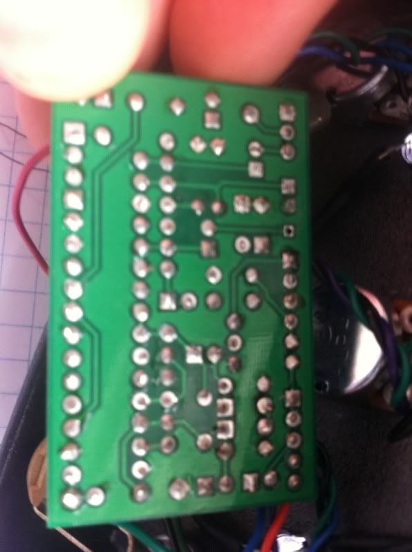
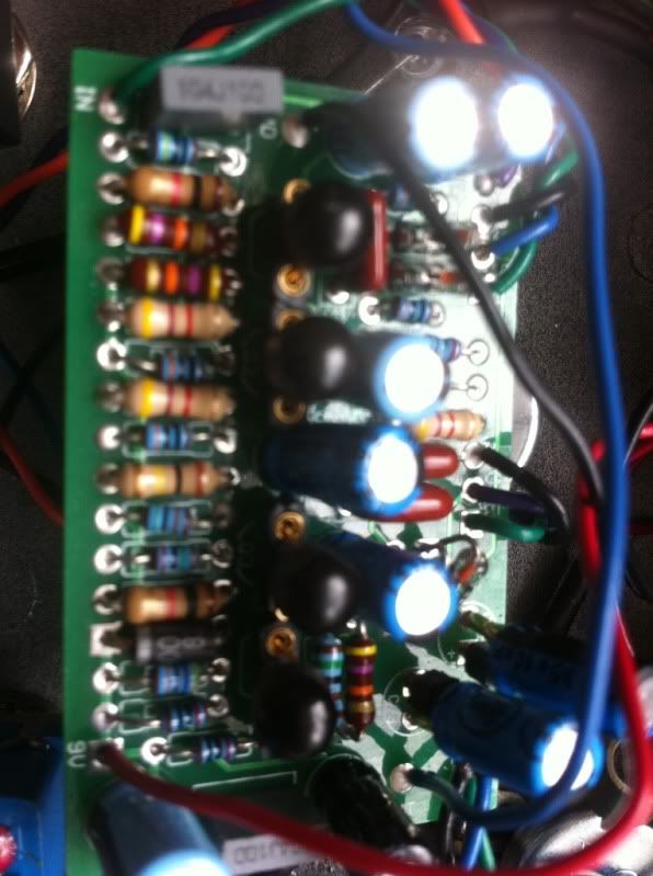
Long story short I bought a mini q-tron 10 years ago and intended to rehouse it and mod it for true bypass. I took it apart and never got around to putting it back together. can I hook up the dc jack like normal or do I need to do reverse the polarity etc... I'm super rusty on all this stuff, its been many years since I got the soldering iron out.  :)


#2
this pedal looks amazing.  are these waterslide decals?


looks like chuck sperry stuff to me:


#3
Mods / Re: serendipity mod: egodriver meets ts9
April 06, 2011, 09:50:43 AM
Quote from: k.rock! on April 04, 2011, 02:37:15 PM
Hey man, did you record any video or soundclip after making these mods? I'd be very interested to hear how your findings sound like :) Thanks!

-Kaleb

you know...i've actually pulled this circuit from my pedalboard and i'm testing out the t-bagger instead.  I never really recorded anything with it either. 

i like it better than the t-bagger so far but it had a huge pop no matter how I wired the switch while the t-bagger is pretty silent.  To me though the circuit itself sounds like a cross between the ocd and a ts style pedal. 
#4
Global Annoucements / Re: Yo Dawg--
March 28, 2011, 02:12:39 PM
looking forward to this one, i'll have to order one soon. 
#5
Quote from: madbean on March 23, 2011, 04:31:01 PM
Here are voltages off two different builds.

8.85v supply

Build #1: the new fabbed board
Transistors: 2n3904 (read C-B-E)
Q1 2.28, .75, .14
Q2 7.17, 2.28, 1.64
Q3 7.02, .8, .18
Q4 7.74, .76, .15


Build #2: ver.1 board
Transistors: 2n2222a (read C-B-E)
Q1 7.2, 2.2, .14
Q2 7.2, 2.2, 1.61
Q3 6.93, .77, .19
Q4 7.72, .73, .17

Q2-Q4 match well on both builds. Q1 in build #1 is close to the result I would expect. The collector in Q1 on build 2 seems way off, so it may have gone south or I might have the wrong collector resistor there. I only played through build 1 this time and just took the voltages off build 2.

Anyway, with the gain rolled all the way down, it's a bit above unity with max volume compared to bypass. With the gain all the way up it has a huge volume boost at max compared with bypass.

thanks.

it looks like the issue is at q1 somehow.  I'm going to probe around and perhaps order some new q's to try I guess.  I appreciate the help.
#6
Open Discussion / Re: Make your time...
March 22, 2011, 11:42:21 AM
what is it?

???
#7
Build Reports / Re: Eagle Sunking
March 22, 2011, 10:56:39 AM
which diode configuration do you prefer so far?
#8
I could use some help still on this, thanks.   :)
#9
Open Discussion / Re: Idea in conjunction with delay
March 16, 2011, 08:30:44 AM
I built the echoplex booster into a rebote delay.  I liked it but had to pull it as it was a tight fit in an enclosure and didn't spend a lot of time on it. 

My idea was to put the ep circuit post delay and mod it for a darker sound (can't remember all what I did but I darkened it up quite a bit).  I also tried it pre-delay as well. 

IIRC I thought it might need to be inserted into the signal path somewhere rather than just pre/post effect.  There is probably a thread here on it if you search (link below) but iirc the idea was to put it on the wet sound only.  Unfortunately I got tied up with other stuff and never followed through (typical for my project ideas  ::) )

as far as the echo park i'd think it might be a nice addition but it also might emphasize the sterile nature of the repeats and make an other wise nice sounding delay a little to brittle and bright. 


here is the thread actually:  (this is for the original design which was minus the fat control iirc)

http://www.madbeanpedals.com/forum/index.php?topic=466.0


#10
General Questions / Re: Splitter box
March 16, 2011, 08:19:44 AM
i'm not sure on the splitter box question but along the same lines here is some possibly useful info. 

On tgp one time I asked if anyone knew how to reverse phase simply with a diy circuit.  Kimock responded that any simple single stage booster will do the trick and I tested it out using the following: slambox, thunderpuss, fat pants and a stratoblaster.  all of them reversed phase on one of the outputs perfectly.

just fwiw/fyi

I was using a boss octave pedal to split the signal at the time. 

#11
whoops. I thought you asked about r19

r9 is the input voltage (my DMM's battery is going out but) on the bottom and a like 8.7 on the top

#12
btw, I don't know how to check the last gain stage or transistors.

I audio probed it and it seemed like there was a pretty big drop in volume at the top of r17 and coming off the middle lug of the tone pot.


#13
Quote from: madbean on March 14, 2011, 07:32:58 AM
You should not be reading negative voltages. Something is obviously very wrong here. Not sure what, though.

Are your transistors socketed, by any chance? If using 2n3565, the flat side of the transistor should be the emitter. For example, from left to right, the flat side of Q1 should be on the left.

What is your reading on both sides of R9? One side should be about 9v, the other somewhat less.

sorry, no negative voltages...bad way to write those out.  the - just separated the transistors.

yes, they are socketed.

here (flat side being 1st)

q1: .15/.82/2.43
q2: 1.8/2.54/8.48
q3: 9.3/.8/.11
q4: 9.9/.74/.08

r19: 10.6 on the bottom, .76 on the top

#14
thanks.  I'm stumped on this one, perhaps one of the 3565's is bad?


the legs of the transistors are (from left to right as you look at the pcb)

0.15, 0.82, 2.42 - 8.1, 2.5, 1.8 - 8.9, 0.8, 0.1 - .08, 0.74, 9.6
#15
Quote from: bigmufffuzzwizz on March 13, 2011, 10:18:33 AM
You always got some good projects ideas! I gotta get drilling for enclosure versatility. Can't wait to see what you put together.

thanks, I was just looking at the enclosure thinking "can I make something outta this?"  If I can find a reasonable way to plug that one large hole in the top I think I can make it work.  It's a pretty sweet box actually, just horribly wasteful to put this small little circuit by itself in there IMO.  :)