News:

Forum may be experiencing issues.

Main Menu
Menu

Show posts

This section allows you to view all posts made by this member. Note that you can only see posts made in areas you currently have access to.

Show posts Menu

Messages - bluelagoon

#1
Open Discussion / Re: Reliable Source for LM308s?
August 07, 2023, 08:20:03 AM
Personally would not trust Banzai, After catching them out selling fake HA1457W Hitachi op amps at a great price, then I notified them to as much that they were selling fakes, they said we will look into it, A year later they are still selling the same fakes as real NOS, Totally unscrupulously oblivious to what constitutes ethics

https://www.banzaimusic.com/HA1457W.html

Don't purchase these, I asked Banzai for an up to date image of actual item being sold back in late 2021, and the image they sent to depict their item was an exact same image and detail as fake Chinese HA1457W IC's I had previously purchased of which none of them worked all duds from a lot of around 50 out of China, All non original fake copies, and bad copies at that.
The actual image Banzai sent me to depict their HA1457W is shown here as 8M4 HA1457W identically marked.
2nd image is an original Hitachi HA1457W, its not hard to spot the fakes with the HA1457W op amps
And while it is, I have purchased a few working fakes of these op amps, the lot of those marked same as the Banzai, from China were all duds, non working, I cant use them, and wont resell them.
And yet Banzai did nothing after I notified them they were selling fakes, likely to this day they are still selling the same
#2
General Questions / Re: Why is my Op Amp smoking?
July 10, 2023, 08:21:50 AM
Probably smoking cause did not read the Surgeon Generals warning on the pack of cigarettes
#3
Released just now:  ".hex code for VFE switching MCU" https://www.vfepedals.com/product-page/hex
:)
And it works a treat, just like the pre programmed ones sold here and direct from VFE
All Good  :) And much thanks to Peter at VFE, and all those that supported his Indiegogo appeal.
#4
Build Reports / Re: Coda Effects Black Hole Build Issue
February 03, 2023, 02:47:14 AM
Was Checking the Coda Web Site, and the Build Doc for the Black Hole says
Q1/Q5 J201
Q2/Q6 J201
Q3/Q7 J201
Q4/Q8 J201
And yet the parts list denotes only 4 x J201 transistors required, So why the Q1 to Q8 listed in a seperate section as if to imply 8 J201's required? Beats me?
#5
Peter Rutter has just launched an Indiegogo fund raising campaign to hopefully get the cash together to purchase the license rights to the Silent True Bypass Relay Switching code that programs all the PIC Microcontrollers used in the VFE effect pedals. To me these VFE PIC MCU's are one of the best for true bypass silent relay switching that are on offer, and while a little similar to the Free code offered by Coda for similar purpose, the VFE PIC works differently than the Coda and is useful in ways that the Coda cannot achieve.. I know that you can write your own code easy enough for a required switching situation, or you can pay someone to write it for you. But what Peter has in mind if he gets the funds together to purchase the PIC MCU license rights, is to make his particular PIC MCU code available for free to all DIY Pedal builders just like the Coda code is presently available.
This simplifies things a lot for those who don't wish the extra curricular of learning to Code Micro Chips.
Making accesable a quality PIC MCU code easy and readily available for use in not only VFE effects but all and any and every effect where you want true bypass with silent quite relay switching incorporated.
This is very altruistic of Peter Rutter giving back yet again to the DIY community, so would encourage any and all with an interest in such things to have a look at the Indiegogo campaign and hopefully be inclined where able to support him in his quest.

https://www.indiegogo.com/projects/help-vfe-pedals-make-diy-available-to-everyone#/


Cheers, Trevor T.
#6
okay thanks Scruffie, needed that help. running in the dark a bit otherwise. Much appreciated,  :)
#7
Yeah more headroom is the idea, the HA 1457 chips can take something like up to 25 volts each rail, apart from that I were looking to incorporate in same box as an existing circuit already on dual supply, So really want to just make everything compatable. So you would reccomend the 3M3 goes to the 0 Volt ground, okay ? Would it be correct then that the only real place the - 9 volt would need placing then would be on the op amps pin 4? Thanks for your reply and assistance.

Cheers, TTay
#8
Hey thanks for your reply Matmosphere.  Thanks for the tip on the 7662 chip.
I aready have the hows and whys of getting the dual supply voltage for the circuit, just need some advice on which parts of the existing single voltage supply circuit needs reconfiguring to adapt to a dual voltage +/- 0 volt ground circuit. like which parts such as involved in the voltage dividing network need scrapping and where the existing grounds go to in a dual supply ? to 0 volt ground or to  - 9 volt and already know the half supply connections from the dividing network go to the new 0 volt ground, just need to understand the rest of the story for this particular circuit.

Cheers.
#9
Hello Fellow Board Members,  :)
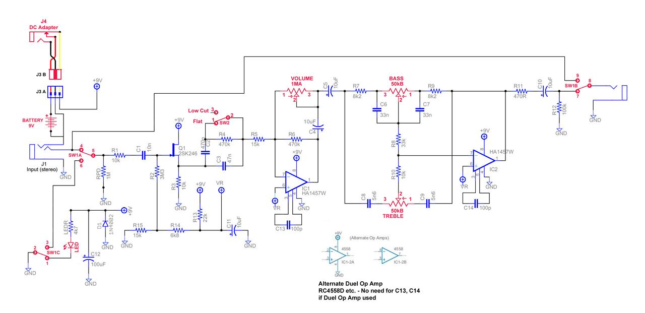
                                             I am in a bit of a quandry, trying to properly figure just how to correctly convert the Boss FA-1 circuit from single 9 Volt supply to a Dual rail +/- 9 volt supply with a centre 0v ground. I realize I shall need an appropriate charge pump to get the dual supply, but really need help to identify just which of the original grounds become -9volt and which stay as 0 volt ground, I understand that the op amp half supply voltage goes to 0 volt just mainly curious on the section circled in orange trying to get my head around, particularly where the 3M3 resistor is supposed to end up either 0V ground or -9volt? also the 1M pull down resistor does it go to -9volt or 0 ground? I see that also the voltage dividing network in there can probably be scrapped. Just need some sound advice on the matter. the rest of the circuit seems a bit more straight forward, but please chime in with every detail needs correcting for dual +/-v supply. Any and all advice is greatly appreciated

Please see attached FA-1 Schematic.


Thanks for your support.

Best Regards,

TTay
#10
I am looking to do the Boss FA-1 circuit only I wanted to do it with a dual rail +9v -9v power supply, or possibly even up to +15v -15v. I just need some education on what changes to the circuit need doing and where exactly the negative volt rail, the positive rail and the 0v needs placing, and also what in particular is now ground reference? is it 0v or -9v The circuit image is shown below. Thanks for any insight and instruction into the matter. Cheers, Trevor

#11
I am looking to do the Boss FA-1 circuit only I wanted to do it with a dual rail +9v -9v power supply, or possibly even up to +15v -15v. I just need some education on what changes to the circuit need doing and where exactly the negative volt rail, the positive rail and the 0v needs placing, and also what in particular is now ground reference? is it 0v or -9v The circuit image is shown below. Thanks for any insight and instruction into the matter. Cheers, Trevor

#12
 :) ??? Thanks