
beside the obvious one that is part tolerance, there is also the silicon lottery. the third thing that I think people are mostly missing or skeptic is the induction. all kinds of induction. everything is an antenna. we are playing with high gain audio amplifiers. ceramic caps create and are influenced by magnetic fields. but lets also be realistic, the induction depends on the presence of AC magnetic fields from both inside and outside the case. a shielded enclosure will mostly only get RF on the cable so there is a length of cable there that is radiating RF before it reaches the first RC low pass. RF + high gain can steal headroom if it is not filtered properly. even if it is it is not since it radiates from the jack to the switch. the more you RC filter this the more you increase the RF load through the wire (also an antenna) this also increases the current through the wire. I built a pedal with a LM386 into a TL072 and it was notorious for induction. this is a function of sensitivity to picking up noise and currents being used by the LM386. it makes no difference if the ripples are generated and picked up in the signal or in the power. for single ended signals the feedback loops are the same result with high gain amps. it does not matter if the noise is coupled to the power rails or to the signal and one of the power rails. it will be amplified at each gain stage. there is ground at 0 Ohms theoretically ideal and then there is ground at G > 0 Ohms. there is wire at 0 capacitance and then there is real wire including the leads of the part have C > 0. don't forget L > 0. all your transistors and opamps have different ground this is exactly what is coupling the induction and power ripple between builds. usually this is very very low less than 1 Ohm but a solder joint can vary depending on oxidation of the PCB and component leads. no one ever notices or records measurements of oxidation that can be as high as 10 Ohms or more even worse on the power or a transistor with beta 100+. you can sort all these things out but you really can't sort the silicon lottery past a point of Hfe and I know that manufacturer, part number and Hfe do NOT tell the story when you are trying to make consistent guitar pedals. it is much deeper than that. you need 4 dimensional data sets, not worth it to check a batch or to check a part. thats where I give up.
- Welcome to madbeanpedals::forum.
This section allows you to view all posts made by this member. Note that you can only see posts made in areas you currently have access to.
Pages1
#1
How Do I? Beginner's Paradise. / Re: Why do some pedals just sound awesome
July 06, 2016, 01:25:14 PM #2
How Do I? Beginner's Paradise. / Re: Green Russian Big Muff voltage problem
July 06, 2016, 12:53:27 PM
check your power supply make sure it is > 8v. turn the power off and measure the collector resistors for resistance. it should be within +/-%20 of the schematic. if you have the right resistors there then check the base voltages with the power on. report back the base voltages.
#3
How Do I? Beginner's Paradise. / Re: Etched vs Fab PCB
July 06, 2016, 12:47:17 PM
single sided boards sometimes do put the components on the same side as the copper but this is usually when there is no drilling. you see it on quick and dirty builds or builds that have mixed SMD and through hole components. it is somewhat easier to solder a radial cap this way laying it down flat than it would be to solder a resistor or diode.

#4
How Do I? Beginner's Paradise. / Re: Soldering 9v jack negative lead to metal case?
July 06, 2016, 12:42:59 PM
if the enclosure is painted or powder coated I sand paper the inside area around the jack to ensure good grounding for years to come. a PCB with a grounded standoff would also work if you don't mind the bolt sticking through the case to the outside. you can buy solder lugs that hang off the pot shafts and ground to the case. search for solder lug or solder terminal 0.25". a smaller solder lug can be used a different way by bolting it to the enclosure.
#5
Build Reports / Re: Picture Showcase - post your best pedal work
July 06, 2016, 02:16:20 AMQuote from: beneharris on May 17, 2016, 08:30:41 PM
Here is my best one, but its just a test rig:
nice one! try this to protect the wire going through the hole. they come in every size.
http://www.mouser.com/ProductDetail/Heyco/G1004/
#6
Build Reports / Re: Fuzz Factory with 7 knobs
September 09, 2011, 01:42:47 PM
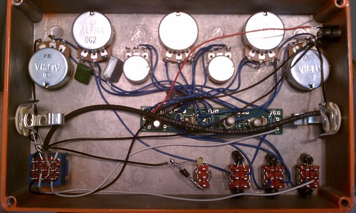
I haven't actually tried them together. I built them on different days and I always drop my stuff off at a local place for consignment. I should just go and grab all my pedals for a proper weekend of fuzz jamming. to answer your questions...the bass switches are all the electros switching to larger values, including the drive cap. so thats 22uf INPUT 22uf DRIVE and 47uf OUT. the input and output caps are so close you should just do 22uf IN and 47uf OUT on every fuzz factory. the drive switch is a small change as well. the biggest waste of space ever. when in one of the clipping modes, you must turn the volume up for clipping. without another volume knob, its completely unusable in a live setting. its just way too loud when using the clipping with vol turned up. I would totally do it again and not use any switches at all. clipping can be done with two volume knobs, "gain" and "vol". the tone control is from the easy face. google it. the grit is just a 250k linear in series with a 100k resistor on BC of Q1. it is useful but can be left out if your dont have space. 7 knobs on a 1590BB is possible with 16mm or 9mm pots. bring back the PCB Mr Bean 
#7
Build Reports / Fuzz Factory with 7 knobs
August 24, 2011, 03:46:53 PM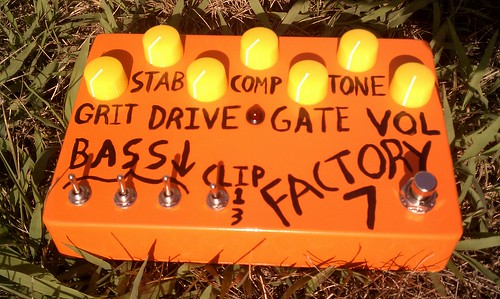
the tone knob is taken from the easy face and works great. the grit is just 100k to 350k on Q1 CB. thats a 100k with a 250k pot.
part of a complete set
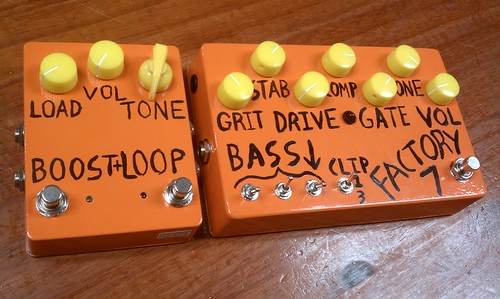
thats a modded LPB on the left. you can switch them both together with one footswitch but you must put the fuzz in the loop of the boost. I kinda f*d up and my diode clipping is dependent on the volume of the fuzz factory. you could just run a volume knob in a box after the fuzz factory and it would switch together with all the clipping and no volume problems. next time I'll just make a 8 knob version with less switches.

#9
Build Reports / 4 knob mangler
August 21, 2011, 03:55:05 AM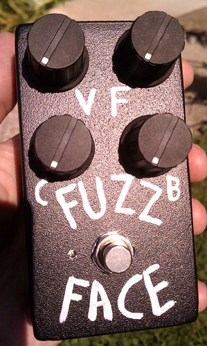
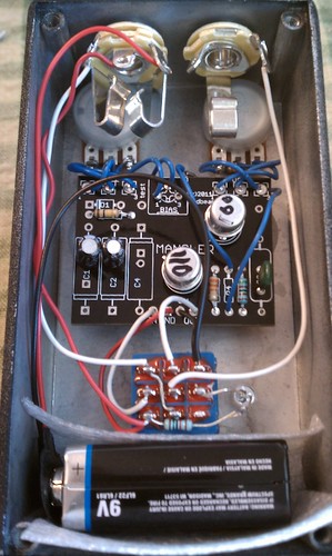
pnp fuzz face with contour (like fulltone 69), and bias on the front. the bias is just Q2 bias. I have the correct bias closer to the full ccw so as you turn it cw you get starved Q2. its a 5k1 resistor in series with a 5k pot. my volume pot is 100ka with 100k resistor on the outer lugs. its weird how different fuzz faces work better on different vol knobs. transistors are japanese germanium TCG102 or TCG1024 or something. I really like it but I would have used a 4k resistor in series with a 8k pot if I knew I could have starved it more. and also the bias is slightly out of range with the contour turned all the way up. I think I should have used all 3 lugs for the contour instead of just 2.
Pages1