News:

Forum may be experiencing issues.

Main Menu
Menu

Show posts

This section allows you to view all posts made by this member. Note that you can only see posts made in areas you currently have access to.

Show posts Menu

Topics - Bieling3

#1
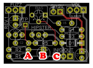
After too much fiddling with the C10 cap trying out different configurations for a mids knob (ya, I should have socketed) I think I've burned out the ring for the hole on the PCB. It's the right leg that connects with R18 and the 3rd lug of the tone pot.

Is it possible to just stretch the leg over to R18 and drill out the offending hole?
#2
I want to add a 100kB linear pot to my Hipster Fuzzface clone as described at fuzz central's Axis Face page:

http://fuzzcentral.ssguitar.com/axisface.php

QuoteThe "Smooth" Control
The next thing that we're going to do with the circuit is to add a 100K linear taper potentiometer to the input of the circuit, between the new pulldown resistor and the input capacitor, to act as a sort of a pregain. This mod was originally put on the Fuzz Face-style circuits by Mike Fuller and the '69 fuzz pedal. We're only going to use the first lug and the wiper lug of the pot since it only needs to act as a variable resistor. This pot will allow you to reduce the "fizziness" of the fuzz, and will also allow you to greatly smooth out the texture of the fuzz. The pot should be wired like this: Lug 1 attached to the input, Lug 2 (the wiper) attached to the base of Q1, and Lug 3 left unconnected. With this wiring the pot will be at minimum resistance when it's turned fully counter-clockwise, and at maximum resistance when fully clockwise.

The schematics aren't all that different between the two but never the less my inexperience has me asking:

Should I wire the pot between "A" and "B" or "B" and "C"?

#3
Just like the title says, no sound. It bypasses just fine and then when you switch it on, nothing. I've had a rough couple of weeks with this thing. I built one last month and had it up and running in a couple of hours. I'm determined to make this pedal work. As per suggestion I've:

QuoteDouble checked my wiring
Double checked my part values
Double checked my part orientation
Double checked my soldering job

....And given it a lot of looks with plenty of time in between to clear my head.

Socketed 2N5088 Transistors read as follows:

Q1

C 6.62
B 1.14
E 0.71

Q2

C 6.63
B 1.14
E 0.71


Q3

C 6.12v
B 1.05v
E 0.62v

Q4

C 3.89v
B 1.14v
E 0.58v

Hopefully I can get some better pics tomorrow when I go back to work at the lab... and also take a toothbrush and some isopropyl alcohol to the board to get all the flux off it...


P.S. Yes, the diodes' legs are long... once the fuzz is up and running they're coming out and a switch is going in. Same with C10.