Show Posts

This section allows you to view all posts made by this member. Note that you can only see posts made in areas you currently have access to.


Topics - lincolnic

Pages: [1] 2 3 ... 5
1
General Questions / Help me identify a jack? String Ringer LFO Depth
« on: November 15, 2018, 09:46:56 PM »
Hey friends,

I haven't built anything in a while, but I'm taking some time off around the holidays and plan to be doing a lot of soldering. One project I'm working on will be the Dead End FX String Ringer, but I need some help identifying one of the switching jacks used in the project. I've attached a screenshot to this post from the build doc, but in case that doesn't work here's a link to the build doc itself:

https://drive.google.com/file/d/1lEGyfLFhGigXvQ8sfUZGQItD3yIR-7y7/view

I'm specifically not sure what I need for the LFO Depth jack pictured on page 5. Any help would be appreciated!


2
Hey guys, I need some help with an older build. I'm about to sell my original ZPSDX, but I've discovered a couple of issues.

First, the overall signal level is getting boosted when the pedal's engaged. What's the best way to solve this? Should I increase R3?

Second, there's a faint ticking in the background when the pedal's engaged. I think it's the LFO, as it speeds up/slows down when the Rate knob is adjusted. The ticking disappears if I touch one of the knobs (they're aluminum), so maybe there's some weird grounding issue?

I should add that everything else works properly and sounds good, so hopefully these issues are easily solved. Since the PCB's been out of production for a while, I'm attaching the build doc so you guys can check the schematic.

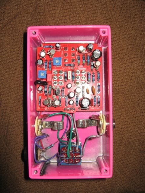
Here's a gutshot. After I took this picture I added a 10k resistor across the Feedback pot to try and tame it a bit, but otherwise everything's as is:


3
Hey gang, I'm wondering about the proper behavior of the Gain 2 trimmer in the Total Recall delay. I've built two of these so far -- one with four MN3008s, one with Xvive 3005s -- and in both of them, I can never get the volume at pin 1 of IC4 to match pin 7 of IC6. Everything in the biasing process goes well up to that point, but then with Gain 2 maxed out, the volume at pin 1 of IC4 is a good 6 dB or so lower than it is at pin 7 of IC6. This behavior happens in both of my builds.

The pedals still work otherwise, and generally sound pretty good (the 3008 one still has some clock noise at max delay time, which I need to figure out), but has anyone else run into this problem? Just how much of a problem is it? If it was just one build I'd think maybe I had a bad trimmer or something, but the odds that I picked two bad trimmers for the exact same spot on two different PCBs are pretty slim.

4
So I finally put my Twin Peaks on the test rig today, and much to my dismay, was greeted with some immediate issues. While the symmetry, shape, tone, and rate knobs all appear to work properly, there's a massively loud thumping sound, much louder than the guitar signal. Turning the depth knob up to around 8 or 9 o'clock seems to trigger it, as does adjusting TR3 or TR4. It was so loud that I immediately took it off the test rig.

Everything is completely stock, no substitutions. VTL5C1s for the vactrols, C22 is socketed and has a 100n in there at the moment. My only thought is that when I soldered the two PCBs together, maybe I had them too close together, and something is shorting out. I was able to slide some cardboard in between them after the fact, but it didn't help (they may be close enough that the cardboard got torn up). But before I do a lot of desoldering I figured I'd ask for help first.

Here are my voltages:

9.0 supply

5532

1. 1.8 - 4.8 varying
2. 3.4
3. 3.4
4. 0
5. 3.4
6. 3.5
7. 2.3 - 5.0 varying
8. 7.1

TL074

1. 4.3
2. 4.3
3. 4.3
4. 8.8
5. 4.3
6. 4.3
7. 4.3
8. 4.3
9. 4.3
10. 4.2
11. 0
12. 2.1
13. 4.3
14. 4.4

TAPLFO

1. 5.2
2. 0.9
3. 2.4
4. 5.1
5. 1.5 - 3 varying
6. 0
7. 1.4 - 3.8 varying
8. 5.2
9. 5.2
10. 3.5
11. 1.8
12. 2.7
13. 2.4
14. 0

I was able to bias B2 and B3 to roughly half of B1 without any trouble (don't remember the voltages offhand and didn't think to write them down, as I did that before listening to anything).

D1 lights up fully when power is applied, but I'm not sure if that's normal or not.

Unfortunately I only have a picture of the main PCB, but I can assure you I've checked the pot PCB and all the resistor and cap values are correct. No photo of the bottom side, obviously. I don't have the momentary tap switch soldered in, would that affect things at all? I feel like it wouldn't, since if the switch isn't being pressed that connection isn't being made anyway, but it's worth mentioning.


The PCBs are just temporarily mounted in the enclosure for ease of testing/photographing. In case anyone's wondering what's going on with the screw holes, I wasn't able to find the nylon screws suggested to hold the boards together, so I just soldered some thick diode legs to the pads instead. I figured since they're not actually connected to anything, it was a permanent enough solution that I could still undo if needed. (As it seems like I'll need to do now…)

5
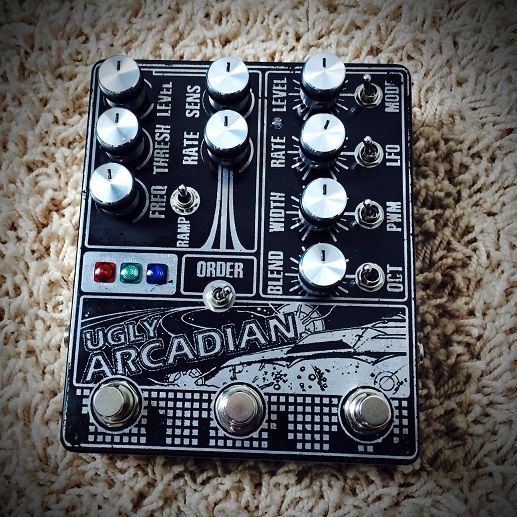
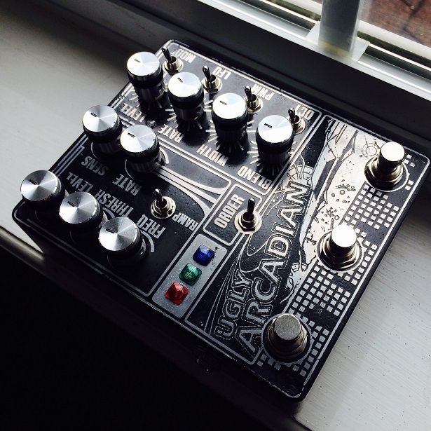
So Dan and I did a second collaborative build, and it's one of the craziest boxes I've ever put together. He talked me into putting an Arcadiator and Machette together into one box, and then proceeded to design the hell out of said box. To whit:


(It's worth noting that all the photos in this thread came from Dan, and he graciously allowed me their use.)


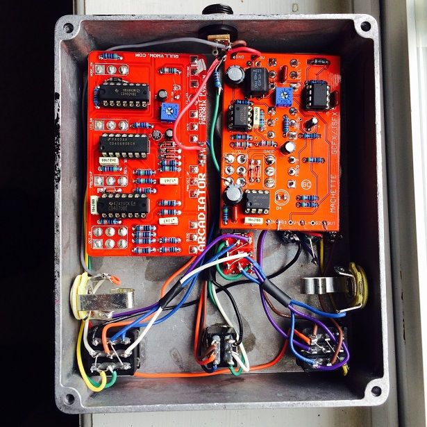
Luckily for me, Dan was agreeable and was willing to overlook his usual taste for off-board wiring. With nine pots and five toggles just on the circuits themselves, anything other than PCB-mounting would've been a real test. (It also would've been a gigantic box -- this is already a 1590XX!) The LEDs work like this: red is for the Machette, green is the Machette's LFO (which is toggled by the middle footswitch), and blue is the Arcadiator. We used an ultraviolet/purple LED for the Arcadiator's LFO indicator, board-mounted between the "level" and "rate" text.

This was my first time including an order switch in a build (having only done one two-in-one before), but other than that it was mostly straightforward. I had good intentions for the wiring, but as usual, they got slightly derailed: I started hooking up the Machette's footswitch in the usual way before remembering that it has a special wiring diagram to cut down on signal bleed. I had to desolder the half of the 3PDT I'd already done and start over. Luckily, the Alpha 3PDTs are robust, and I had no trouble there. When I went for the final post-box test, I noticed that the Arcadiator's LED wouldn't light. I reflowed, checked for cold joints (the CLR there used to have heat shrink on it, but I snipped it off to make sure the connection was good), reversed the lead, and still got nothing. The LED was just a dud. So that also helped un-neaten some of my previous work. Admittedly, I also got a little impatient with all the re-working I had to do and could've tried harder to keep it cleaner.


I used the last of my wire boxing this thing up, but I have some more arriving tomorrow or the next day, so I'll be able to finish my own sometime this week (I sent this off to Dan as soon as it was done). If I manage to improve on the guts in a meaningful way, I'll make another build report.

I just realized that I've written a lot and haven't said anything about how it sounds. The answer: completely insane. Each of these circuits can do so much on its own, and when you combine them (especially with both LFOs engaged) you can get some real throbby chaos going on. I'm actually surprised at how much I like the Machette on its own -- I wasn't sure what to expect, but I found myself dialing up some kooky early Brian Eno sounds that made me happy. I was also having fun with switching the Machette to be first in the chain, setting it up to generate signal, and feeding it into the Arcadiator.

Of all the pedals I've built to date, this one definitely has the highest learning curve, but the sheer variety of sounds it can make is worth the effort.

6
Tech Help - Projects Page / Arcadiator trimpot setting help
« on: April 17, 2015, 09:39:59 PM »
Guys, maybe (probably) it's because it's late and I'm tired, but I can't seem to figure out how to set the trimpot on my Arcadiator. It doesn't seem to be making a huge difference whatever I do. Can someone explain it to me? The rest of the circuit seems to be working properly, as far as I can tell.

7
Open Discussion / The 57th Strat ever made
« on: April 02, 2015, 03:01:29 PM »
Seriously. Its serial number is 0057.

https://reverb.com/item/582117-1954-fender-stratocaster

A beautiful guitar to be sure, but do you think it'll ever be played by whoever buys it? (I'm assuming some rich person will buy it eventually.)

8
Tech Help - Projects Page / Arcadiator IC question
« on: April 01, 2015, 09:37:55 PM »
I've seen some reports of people having trouble with their Arcadiator because of chip variations -- I think it's the CD4069? Can someone confirm which version of this chip is the one that works (or doesn't work)? I haven't built mine yet, but I have the sneaking suspicion that I've ordered the wrong ICs. Hopefully I can nip this in the bud before I get it on the testing rig.

9
General Questions / Fresnel LED bezel question
« on: March 06, 2015, 06:00:52 PM »
To those of you who've used fresnel LED bezels, have you found it better to use them with waterclear LEDs, or are diffused LEDs bright enough to be seen through them easily? I'm aiming to use fresnels on an upcoming build but I'm not sure if one type of LED would work better than the other.

10
General Questions / Any issues with two LFO circuits sharing power?
« on: February 19, 2015, 11:09:33 PM »
This might be kind of a dumb question, but I'm gonna ask it anyway. I'm in the planning stages of a 2-in-1 build, with each circuit having an LFO (in this case, the Machette and Arcadiator). I know sometimes you can run into heterodyning issues when you have two different circuits with clock chips sharing the same power, but is there any kind of similar issue with two different LFOs?

I don't think there is, as I see tremolo and phaser combos pretty frequently, but maybe there's something else I need to learn.

11
General Questions / Mudbunny jack/drill template question
« on: December 02, 2014, 11:40:54 PM »
On the Mudbunny drill template, I notice there are specific jacks used (I'm guessing in order to have enough space for the battery). Which jacks are these?

Would regular open frame jacks be too big to include a battery in a 1590B? Gonna build one of these for a customer and he'll want the option of battery power, so if I've got to get specific jacks I'll pick some up.

12
General Questions / Anyone in Brooklyn have something to test MN3008s?
« on: October 06, 2014, 09:20:42 PM »
Bit of a long shot here, but I figured I'd ask anyway. I know there are at least three of us here in Brooklyn (me, Droogie, thesameage - anyone else?). I just bought some MN3008s from the same eBay seller that everyone else here did, and while I think everyone's received legitimate chips, I've got nothing to test mine in. Do any of you guys have a build I could drop these into to see if they work? I'll buy you a beer or a slice of pizza or something.

If so, we could meet at my studio to check things out. Let me know! Worst case scenario, I'll test them whenever the DBD3 is finally released, and I'll either be happy or I'll be out $25. Not the end of the world.

13
Open Discussion / MXR 126 Flanger/Doubler - similar to 117?
« on: August 31, 2014, 10:56:17 AM »
I've been wondering about this for a little while, and I figured this was the best place to ask. Does anyone know if the old blueface MXR 126 Flanger/Doubler is a similar circuit to the 117? We have a 126 at my studio, and it sounds fantastic, but I know it's got a SAD1024 in there (along with another rare IC) and I feel like it's only a matter of time before it goes. Does the 117 share any of the flanging circuitry with the 126, or are they very different?

126 schematic, if that helps: https://dl.dropboxusercontent.com/u/33143162/MXR%20M126%20Service%20Schematics.pdf

14
Build Reports / Lamprey - jubal81's SFT in a 1590B
« on: August 21, 2014, 12:15:30 PM »
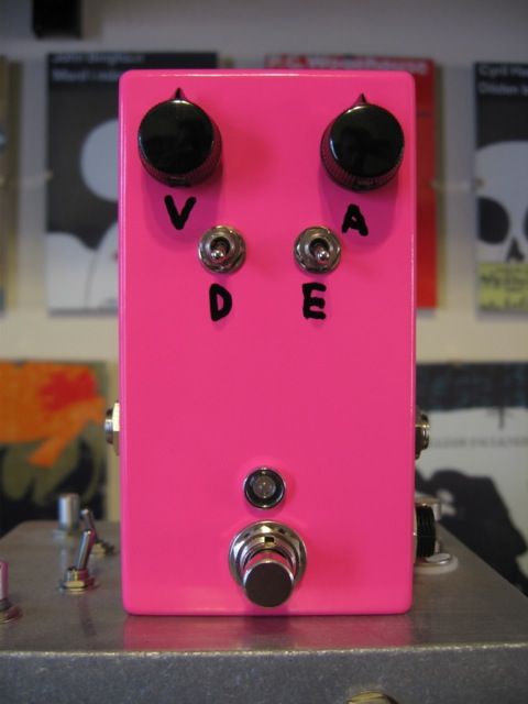
Over the weekend, I finished up three projects: twin1965's V Fuzz, midwayfair's Rustbunny, and now jubal81's Lamprey (the SFT). This build wasn't super eventful, but it's worth noting for a couple of reasons.

The PCB was intended to fit into a 125B, but I much prefer 1590Bs. I asked Jason if he thought it would still fit, and he said it would, so I dove in. Turns out, it does fit…barely. After some very careful measuring and drilling, I still had to flip the PCB component side-down, but otherwise it fits over the jacks and under the backplate without touching either. Since everybody always says this circuit sounds so much better at 18v, I also made sure to leave room to include a spare Road Rage I've had sitting around for a while. Double-sided tape insulates it from the enclosure and holds it in place.

The enclosure is Laser Navy from PPP - it's actually a little bit darker with a more subtle sparkle in real life, but my camera's flash made it pop a little bit more. I labeled it with a metallic silver Sharpie, though it looks white here (again, due to the flash).


You can see how tight everything is in the gutshot, but there's no pressure or stress on the board when I close it up, so overall I'm fairly pleased with how it came out. It sounds good, and I intend to use it for home bass recording. Thanks to Jason for the nice PCB!

15
Last December, midwayfair did an extremely generous PIF and I was lucky enough to receive one of his hand-painted enclosures. I was already interested in his Rustbunny (modified Sam Ash Fuzztainer) circuit, so I knew that's what I had to put in this box.

After spending a couple of months unable to decide on what I wanted the artwork to be, I eventually told Jon to just go ahead and do whatever he wanted; I trust him. While he was working on that, I went ahead and built the circuit on vero from the Tagboard Effects layout. Work and other real life stuff kept me from wiring it up for a while, but I finally finished it on Monday.

It's hard to take a good photo due to the lighting in my room, but I think you guys will get the general idea that this is a pretty rad enclosure:


What you unfortunately miss due to my poor photography are some of the finer details: bits of metallic silver in the clouds, some gold in the grass, definition on the birds, etc. It's pretty obvious that Jon put exactly as much care into this box as he does for his own builds, and I'm so grateful to him for this. I'm not great at decorating my own builds, so it means a lot to me to have an enclosure he painted. I've been a fan of his work for as long as he's been showing it off.


Like most of my vero builds, the wiring for this started out neater but then got away from me a little in the boxing. The wires to the gain knob in particular were supposed to be a bit more elegant. At least the switch wiring is fairly tidy!

As for the sound of the pedal, Jon's original demo does a much better job of showing it off than I could, so I'll repost that here:


Big thanks again to Jon for the enclosure, and for the circuit design. I'm really enjoying the sound of this one just as much as I enjoy looking at it!

Pages: [1] 2 3 ... 5