News:

Forum may be experiencing issues.

Main Menu
Menu

Show posts

This section allows you to view all posts made by this member. Note that you can only see posts made in areas you currently have access to.

Show posts Menu

Topics - mgwhit

#1
Open Discussion / Hum using Boss AC-2 out to PA
March 07, 2015, 12:14:24 AM
I'm playing a gig Saturday night where I'd like to use my Boss Acoustic Simulator pedal with its effected output going straight to the PA, but whenever I do this both my amp and the PA hum like crazy.  I'm assuming it's a ground loop issue, but my PA doesn't have ground lift.  Would it be a potential problem (i.e. dangerous?) to rig up an enclosure with one grounded jack for connecting to the pedal and an isolated, non-grounded jack for connecting to the PA?

I suppose I could just disconnect ground on one end of the cable, too, but a specific enclosure seems like a simple, reusable, put-it-in-your-gig-bag solution.

The stupid thing is, I ran the AC-2 like this at a show a couple years ago, and don't remember having this hum problem at all.
#2
Open Discussion / Inkscape and font rendering
September 19, 2014, 08:07:31 PM
I'm using Inkscape on Mac OSX to design my waterslide labels, and I've just bumped into something I've never noticed before.  I have the name of the pedal in a large font spanning the width of the label, so the left side of the first letter and the right edge of the last letter are aligned with the right and left edges of the graphics above and below them.


When I go to save to a PDF (which is what I usually do before taking my graphics to a print shop), the text enlarges down and to the right, just enough to visibly ruin the spacing and alignment.


(Apologies -- the two screen caps were made at different levels of magnification, but you should be able to see the issue.)

It does the same thing when I do a Print Preview function...unless I set the Backend to bitmap instead of vector.  This got me thinking, so I did an Export Bitmap at 300 dpi re-imported it into my SVG file, resized it to match my vector image and did Print Preview the text maintained its alignment and size, but the rounded edges of my graphic were disfigured!

Any idea what could be going on with the text and how to prevent that?
#3
There seem to be a lot of threads where people suggest that the PT2399s they bought from Tayda were noisy or simply non-working.  I haven't ordered from Tayda in a long time, but I need to this week and was wondering if I should throw a few in.  I suppose for the price I can afford to experiment.

Are there multiple manufacturers of legitimate PT2399s?  If not, are Tayda selling clones or work-alikes (or fakes)?
#4
Forum member jimmybjj was kind enough to let me try out one of the extras from a small batch of Sparklehorn PCB's he recently had fabricated.  One of my bandmates had been bugging me for a overdrive/delay combo for some time, and I had just ordered some PT2399s, so I was thrilled to get an opportunity to try this one.  As you can see, it came out looking pretty nice.  I'm not 100% sold on the overdrive yet, but that's probably because I haven't used the recommended op-amp.  I will fill in some extremely long-winded details in my next post.


#5
Building a Sparklehorn, and it's my first PT2399 delay.  It was a bit of a rush job so I didn't order parts specifically for it.  Finished populating the board tonight except for the 15n cap at C16 -- didn't have it.  I've got 10n and 22n available.  Is this a value I can fudge, and if so how will it affect the circuit.  I can't tell if it's a tone filter or if it affects timing.  Thanks!
#6
Here's my MadBean Boneyard in a remarkably flaw-free Mammoth Vintage Orangle Sparkle Translucent 1590BB.  The Bypass footswitch operates a red LED on the left, the Gain footswitch switches between Crunch (Green LED) and Crush (Blue LED) modes on the right.  The toggle switch is for symmetric or asymmetric clipping, and is just a DPDT On/On with either a jumper or another red LED for D4.  I did a half-gain mod (R5=100R, C5=1u), as I thought full gain was just too much.  I also included the low-pass filter on the output, as this is a very bright circuit.


I gotta admit, I love how this came out.  I'm happy with the look, and I'm thrilled with the sound.  Haven't used it in a rehearsal setting yet, but I plan to give it a spin later this week.

I'll post the gut shot and some gruesome details a little later this morning.
#7
Build Reports / Aqua Velvet (MN3007 Pork Barrel)
July 20, 2012, 01:30:11 PM
I had bigger plans for this build, but, after watching the completed board languish for months while I never got around to those bigger plans, I decided to just go ahead and box the sucker.


First off, I was planning to actually do some nice graphics on white-background laser printer waterslides, but my graphics skills are awful and I could never get anything I was happy with.  As usual, I fell back to my old text-only "let the name do the talking" graphic style.  The Mammoth enclosure had a LOT of flaws (you can see one up by the 'A' along the top), but I think I covered most of them up.  I ended up liking the color more once I got a few coats of clear on it and the whole thing assembled.  I think it looks pretty retro-spiffy.


I had also gone back and forth about cramming a Road Rage into this guy.  I tested it at 12V when I built it, and it does sound noticeably better than 9V.  However I must've designed the decal when I was in a "no Road Rage" period.  Once I realized I had already labeled it "9-15VDC" I decided that adding the Road Rage was a recipe for future disaster.  I can live with this.


Check in the lower left corner.  I was so concerned about making room for my jacks that I accidentally drilled the hole for my power jack too close to the screw well.  I can't take the nut all the way to the wall of the enclosure, but it's holding just fine.

I also socketed R39 in case I decided to do the LFO indicator mod.  I even bought a light plate for this, but wasn't happy with how it fit the enclosure -- it's a bit larger.  I'm putting this on the "maybe one of these days" list.

My only real mod to the circuit was that I subbed a 4580DD for the 4558 in IC1.  I think it took some middiness out of the signal and added some sparkle.  I'd love to hear if anyone else has tried another dual op-amp here.

All in all, I'm happy with the appearance and thrilled with the sound.
#8
Here's another one I finished last fall.  I was originally going to go with the waterslide on the left, but after watching a certain documentary a friend talked me into going with the one on the right.


Here's the enclosure after a bake in the oven.  I had heard that clear coat didn't work well on bare aluminum (maybe because there's no primer), but I've never had any problems with this one and I think it looks great.  I used a flat clear instead of a gloss, and you can barely even tell it's been finished.  (I used a gloss clear on another bare enclosure and did not like the way it looked.)


Even with all those knobs and wires, getting this in a 1590BB was a snap with room to spare.  I like it when I can mount the jacks on the top to save horizontal space on my board.  I built this Chunk Chunk board to guitarpcb.com "Boogey 57" specs with 2n5457 JFETs primarily because I hated the fizzy sound of most of the YouTube videos with J201s.  Despite the name I was really looking for a more alt-rock/pop-punk high gain than a metal tone, and with the right guitar and amp I can dial that in with this.

Through my tele and 5F2A Princeton it sounds kinda ridiculous.


Here's the finished product.  When I decided to build this one, I kinda thought it was going to be a goof, but my bandmates like this best of all the pedals I've done (okay, along with the Fat Pants, which is currently on one of their boards).  I should probably replace the nylon 3PDT washer with a metal one so that it lives up to its name.


#9
Build Reports / Guess what I'm boxing up today...
May 27, 2012, 01:05:52 PM
#10
Build Reports / Violet Ram's Head Mudbunny
May 24, 2012, 02:40:09 PM
I just went to check my voltages on this for a Tech Help post and realized that I had never posted a build thread, so here goes.

Here I'm preparing to drill out the top of the enclosure.  I'm not really going to start with that unibit -- must've been left on the drill press from a previous outing.  I only use that one for the power jack.  I usually start with a punch for the center of each hole and then a 1/8" starter hole.  I've printed out a paper copy of what will eventually be my waterslide and affixed it with double-sided tape.


And here are the waterslides themselves.  Two in case of an emergency (although I tend to be less conservative these days).


I wish I hadn't used so many carbon film resistors.  Big Muffs are noisy enough as it is.  I also wish I would've gone back and tweaked the mids like I wanted to, but sloth prevailed.  Lotta space in that 1590BB, but it's still more pedalboard friendly than a real Big Muff.


The finished product,  The silver sparkle (pedalpartsplus) shows through the purple lettering a little bit, which looks great in real life.


Even got a violet LED for it just to complete the look.


Around the time I was working on this I had posted a Tech Help thread because the gain was through the roof, the tone knob didn't have much useable play and the volume was instantly on.  I set the board aside for a while and when I came back to box it up I noticed that I had mixed up the pots.   :P

I think this pedal sounds phenomenal, but because of the mids situation it can get lost in a band context.  My solution: tell everyone else to back off.


#11
General Questions / FatPants 2012 in a 1590A...?
April 29, 2012, 01:56:40 AM
Anyone know if the new (2012) FatPants boards will fit in a 1590A?

One of the guys in my band loves mine, but wants me to do another for him with custom graphics...and specifically in a 1590A.  There's no way I would have tried this a month ago, but now, having read the Baby Board build guide and seen all of the fantastic Baby Board builds that rolled in today I'm tempted to give it a try with some of those low profile jacks from SmallBear.

If not, I'll be posting a WTB for the old board.  :P  Thanks!
#12
I finished my Pork Barrel board last night, and after one false start (never put a voltage sag knob on your test rig unless it has a detente at one end or a built in switch) got it up and running and sounding pretty good.  I used the 3007 chip, so I tested it at both 9V and 12V.  I've got a Road Rage on a rotary switch on my test rig, so I can go back and forth very easily, and I think 12V sounds noticeably better. 

However, I think the buffered/blended signal sounds a little, dare I say it, midrangey.  Could this be the 4558?  Could this be my brain?  Has anyone tried alternate op amps for IC1? Any recommendations?  I've got some 4580DD's, TL072's, LM833N and NE5532P's laying around I could try, but only so much willpower.

Also, I measured my B100K pots before I soldered them on, and one of them was 99K, but the other was 91K.  :(  
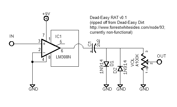
I looked at the schematic and it looks like both of them are just being used as voltage dividers, so I figured it might be okay as long as the value was close enough and the taper was truly linear.  I went ahead and soldered it in as my Depth pot since I'm planning to do the Depth-increasing LFO LED mod anyway (R39 socketed).  Is that value affecting my maximum (or minimum) Depth?
#13
C7 is 100n on both the Red Llama and Tube Sound Fuzz versions of the Snarkdoodle.  On previous versions, the board was spaced for a box film cap, but the pads and silkscreen on the 2012 edition seem set up for a ceramic disc.  Any idea what's up with that?

Also, does anyone understand the function of C7 in this circuit?  It appears to connect the 9VDC to pin 8 of the IC, but wouldn't a capacitor here block the DC?  It doesn't appear to be present in other schematics I've seen.
#14
To add the LFO indicator, the Pork Barrel build doc says:

"Omit R39 from the PCB. Run a wire from the R39 pad on the right side of the PCB to one
lead of a 22k resistor. Attach the other lead of the resistor to the positive lead of a High Brightness 3
or 5MM LED. The negative lead the LED goes to the 3PDT switch to toggle it on and off with bypass."

If I were to connect the cathode of the LED back to the other pad of R39 would that just keep the LFO indicator light on all the time (i.e. even when the effect is bypassed)?  I'm assuming based on the schematic that that pad is just connected to ground.
#15
Spring Break fun continues with another old board finally boxed up!  This time it's an old Fat Pants crammed into a 1590a.


I had a bear of a time cramming this all in, and then, when I finally finished, I realized I had wired the Boost pot backwards.   :-\   
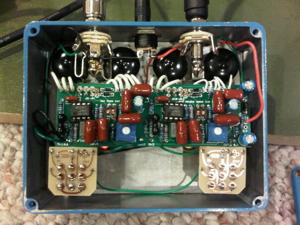
I didn't want to pull everything out again, so I managed to desolder and resolder the wires working entirely from the surface of the board.  I'm sure the joints aren't exactly up to NASA standards, but they work just fine.


Sounds good by itself, but does anyone have opinions on where to put this in your chain?

I'd like to say that this is the last 1590a project I'll ever do, but I've got a completed Thunderpuss board just sitting on my desk and staring at me.  At least the new Baby Board build guide has that nice 1590a drill template.
#16
Build Reports / King of Rock (Aristocrat)
April 10, 2012, 02:56:28 AM
This is the first MadBean board I ever assembled, but for a number of reasons I never got around to boxing it up until today.  I made a total hash of the first enclosure -- bad finish, bad drilling -- and eventually just threw it out and started over.  I think I used 33n caps for C1 and C12.  Red channel has the high gain option.


I finished all the wiring this afternoon, but the Red channel wasn't working.  It had worked outside the box, so I figured it was a wiring error or a short.  Signal was disappearing at R10 on the board, and it turned out to be a bad joint on the Tone pot.  Luckily I was able to get my iron underneath the board and fix it pretty easily, but that meant I didn't finish until my five-year-old was in bed.  Sounds pretty weak at low volume, but then again what doesn't?  I'll give it a real workout tomorrow morning.


The 3PDT PCBs and pot condoms are from GuitarPCB.  The eagle-eyed among you may have noticed the 4558's on the board.  I don't remember putting them in there originally and I didn't notice them until after I took the photos.  I've since swapped in 4580D's on both sides.
#17
I wasn't paying close enough attention on my last component order and accidentally bought some 22nF box film caps that are 7.5mm wide, way too big to fit the C1 and C12 spots on my new Slow Loris board.  (I know it's my own dumb fault, but why Tayda even stocks these things is beyond me.)

I could probably fit one in the C1 position, but it would have to rest on top of R1 and R11.  Would that cause any problems?

I've got an extra 33nF cap I could use, too.  If you were going to sub a 33nF in C1 (input) or C12 (tone filter), which position would you prefer to use it in?  Thanks!
#18
I've managed to misplace my last sheet of laser printer waterslide decal, and I'd really like to finish some enclosures this weekend.  I've never found it looking at Staples or Office Depot.  Are there any kinds of places that carry this stuff?  I can't imagine that you can only find it online.

UPDATE: Hobby Lobby has something they call "Image Art Waterslide Transfer Paper", but it sounds strange.  They describe it as "for glass" and mention that it produces "beautiful sepia tone results once fired"!  They also mention that it is "designed for laser printers with iron oxide toner".  I have no idea what kind of toner my HP uses.
#19
Open Discussion / Is my LM308N hosed?
August 27, 2011, 05:32:33 PM
A few weeks back I wanted to experiment with diode clipping in a simple distortion circuit, so I breadboarded Dead-Easy Dirt (http://www.forrestwhitesides.com/node/93), set up an eight-position dipswitch for different diode combinations, added a few resistors and capacitors for tone shaping and learned quite a bit.

Since I've always wanted a RAT, I ordered an LM308N.  I still had the Dead-Easy Dirt breadboard laying around, so I replaced the LM386 with my new LM308N, rewired for the different pin-outs,removed most of the unnecessary components, plugged in and...nothing.  Here's the basic gist of what I've got on the board:


Voltages are like so:

1: 9V || 8: 9V
2: 0V || 7: 9.5V
3: 0V || 6: 8.9V
4: 0V || 5: 0V


I've tested with a signal tester and  I get clean signal on pin 3, no signal on pin 6.  I should probably say no guitar signal -- it picks up and amplifies some crazy church radio station just fine (as do all of my breadboarded and unboxed effects).  That makes me think that the LM308N is still functional and that I'm just missing something.

Any help much appreciated.  Thanks!
#20
I finished a Mudbunny last night with Violet Ram's Head specs and the Mids knob omitted (jumpered).  The gain on this thing is out of control.  I typically get about unity gain with the volume knob set between 8:00 and 9:00.  I'm not really familiar with playing through a BMP, so I don't know if this is typical or not.

Other than that, it's pretty much what I expected -- big, hairy wall of fuzzy distortion -- and there's plenty of usable tones there.  There's just no subtlety whatsoever.

(There's also very little useful space on the Tone knob outside of 11:00 - 1:00, but I understand that's fairly typical and I don't feel like I need it.)

For what it's worth, I ran the specs for each variety through a BMP gain calculator formula, and the VRH should have much more gain than the Triangle and Russians, but less than the Mayo and (obviously) the Creamy Dreamer.

If anyone else with a Violet Ram's Head Mudbunny would like to comment on the gain level I'm getting I would appreciate it.  Maybe there are some voltages I can check on the transistors to see if I'm running hot.  Thanks!