News:

Forum may be experiencing issues.

Main Menu
Menu

Show posts

This section allows you to view all posts made by this member. Note that you can only see posts made in areas you currently have access to.

Show posts Menu

Topics - Thomas_H

#1
Hi guys,

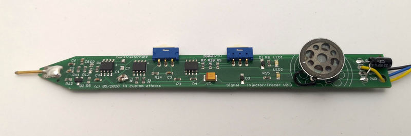
after some long silence I have put up speed again and I am trying out a few new things.
I set up a project to try out PCBA (PCB and Assembly) service.

I wanted to create something usefull, so knowing that a lot of support requests sooner or later have the question: "Did you use a signal probe to veryfy your circuit?" I created this:

Link to demovideo on YouTube:  https://youtu.be/C7YJBo8ySLI


Signal tracer/injector pen features:

  • handy tool - thus the pen design
  • powered by 9V pedal source
  • switchable signal generator burst or alternating (950Hz/1050Hz)
  • switchable instrument (200mV) or line (2V) signal level
  • amplifier and mini loudspaker in(on) the pen
  • SMD components already soldered

Do you think this will be usefull for the community?

yours
Thomas
#2
Its been a long-taking project but its comming.
I need your input on this.

Please join the feature polls to provide me with your opinion.
http://www.madbeanpedals.com/forum/index.php?board=49.0

Thank you!

Thomas
#3
Open Discussion / PRS SE 20 amp - schematic anyone?
December 17, 2014, 02:59:41 AM
I shot a PRS SE 2 Channel on evilBay and it could need some rework soundwise.

Does anyone have a schematic by chance?
#4
This is a custom build after a clients request.

He is playing acoustic guitar in a band context and wanted to be more versatile.

The unit has gone through a few stages which are documented here.
The first try was to use standard switches but he soon found out (what I said) that they make a lot of noise in this huge enclosure.
So we switched it out later for a Effect Control Unit when it was comming in.

So, this is what is in the unit (and the flow of signal from top to bottom)


  • TH custom Valvetizer V1.5 in the clean version using an 12AT7 tube. It was done without the tone control (always on)
  • TH custom 5-band EQ (always on)
  • Jon's Bearhug Compressor
  • madbeans Porkbarrel (CE2-Chorus)
  • madbeans SeaUrchin (Delay)
  • TH custom reverb V4
  • TH custom Processor V4.1(Filter/Splitter/Mixer) (always on)
  • TH custom balanced Line Driver (XLR-Out) (always on)

here are the steps of creation:

Laser engraved in the fitting test:


From the inside. Switch wiring:


From the outside. Knob color samples:


From the inside: Switches replaced with Effect Control Unit:


Knob colors and LED colors choosen by customer:


A look at the splitter/mixer jacks. You can loop in other effects here and mix them in or you can add a secon guitar or whatever ...


Backside with In/Out and XLR-Out. Power jacks are connected to allow chaining other devices.


Live on Stage! Look down at the feet of the guitar player.

#5
You might have seen the 125B version in an earlier build report here: http://www.madbeanpedals.com/forum/index.php?topic=17210.0

Some crap playing sound demo:
[soundcloud]https://soundcloud.com/th-custom-effects/tube-driver-at07-tube-sound-demo[/soundcloud]


I have changed a few parts values and the tube to AT7 and this is sooooo great sounding. Lots of fun and great distorted tones testing this baby!
I will do another recording when I have time.

Now here is the mentioned 1590BB version with the tube inside!
This is the outside. No tube ;-), just a plain black stomp box.


After a lot of thinking how to fix the tube inside the enclosure I came up with this:
(Wiring isnt very tidy as I had to flip the stomp switch because the tube did not fit anymore :-) )


Some detail:
Tube is held in place by a L-shaped piece of plastic which has a 18mm hole for the tube socket to go through. The plastic is mounted to the bottom of the stomp box. Connection to the board with flexible wire and connectors to allow easy access.
There is a separate board to mount the tube socekt and the connectors.


I will do a new board revision which has some optimizations to the layout allowing even easier placement of the tube and board.
It will be available as a GroupBuy. Watch out for it the next days.
#6
Build Reports / Tube Driver - Sound clip added!
August 29, 2014, 01:01:51 AM
Hi,

finally I managed to cram this Tube Driver into a 1590B enclosure.
Although it worked with a lot of time spent I can not recommend this. Use a 125B and you will have easy going ;)

I am still tweaking this a little at the moment but build to the known specs it sounds like the real thing.
There is some more background info here: http://www.madbeanpedals.com/forum/index.php?topic=17209.msg163886

Here are some pictures:


#7
Open Discussion / NAD! Laney IRT Studio
August 15, 2014, 07:57:47 AM
Hi guys,

I had to have one and here it is:

Laney IRT Studio (15W)
Its a little noisy but real fun to play with!
Three full channels (Clean, Rhytmm, Lead) and great sounds!


#8
This is him...

... protecting the secrets papers on the workbench ...

                                   ... sleeping

:-)


#9
Open Discussion / If there were a DIY metronome ...
November 21, 2013, 12:00:51 PM
...what would you be looking for?

- range 40-240bpm ?
- tap tempo switch ?
- LED indicator
- sound switchable between woodblock and cowbell?
- option to do "count-ins"?
- which beat and division pattern do you like to see?
- other things ?

your input is highly appreciated!

Thomas

#10
Build Reports / Set of runoffgroove boards (Thor)
November 15, 2013, 12:20:19 AM
In the series "one runoffgroove effect per day" we continue to show whats in the box.

Here is: Thor!
Not really beeing 100% orginal but people tell me they find the added Bandaxall tonestack really useful.


And this is how it sounds:

[soundcloud]https://soundcloud.com/th-custom-effects/rog-thor-demo[/soundcloud]
#11
Here is the next one.

The Supreaux-Deux:


[soundcloud]https://soundcloud.com/th-custom-effects/supreaux-deux-demo[/soundcloud]


#12
Build Reports / Set of runoffgroove builds (Azabache)
November 13, 2013, 12:31:41 AM
One-build-per-day seems to be the frequency I can focus my mind on publishing here.

So, from the depths of this box,
I present: the Azabache:


And this is how it sounds:

[soundcloud]https://soundcloud.com/th-custom-effects/azabache-demo-1[/soundcloud]

[soundcloud]https://soundcloud.com/th-custom-effects/azabache-slide-demo[/soundcloud]
#13
Build Reports / Set of Runoffgroove builds (Umble)
November 11, 2013, 02:14:57 AM
I forgot to post the prototype builds I had done half a year ago.

Here I present: The Umble.


and how it sounds:

[soundcloud]https://soundcloud.com/th-custom-effects/umble-demo1-clean-lowgain[/soundcloud]

[soundcloud]https://soundcloud.com/th-custom-effects/umble-demo-2-mid-gain[/soundcloud]
#14
Open Discussion / Laser engraving -question
July 13, 2013, 11:09:00 AM
Hi,
I tried to get a black powdercoated Hammond 1590A laser engraved.

This worked fine in the way that the laser has cut sharp graphics into the paint.
But for some reason the lines are not silver shining as you would expect but dull grey.
Yes, the laser has cut in the aluminium. If you use a sharp needle you can scratch throug the dull surface and get silverish aluminium.

Any idea what I have done wrong?

#15
This is YAM (Yet Another Muff) that was also born as pre-production study.

Larger one is a 1590B size, small one is 1590A. Both circuits are identical !
And I am very proud that I managed to get the mini board done without any 1/8W resistors. they are all your standard 1/4W size.

Not telling what their magic is, just that it is the best of all worlds   8)


1590B


1590A


#16
I am proud to present two of my babys that were born as pre-production units.

The Autobahn-Drive  ;D

Those are actually based on the DOD 250 with a few gimmicks.
feel free to visit my site to find out more.
The small one is actually even smaller than a 1590A, its a 1550A !!!!


Here you can see what is inside:

Standard 1590B


Super Mini 1550A
#17
How do you store your resistors ?
I am not sure what the best way is to do that but I found that using a drawer cabinet is not optimal - once you have your values sorted into it you are fine - but when a new value comes in later - do you really rearrange all values to get it in between ? NO!

So for quite some time it looked like: ;D


Yesterday I saw this box. And I had an idea!

I found some strong paper and cut it into strips. Then I labeled it and put it into the plastic bag. Securing the bag and the paper with some clear film.


Before that I made sure the box holds 3 rows the width of the playstic bags and used the cover cut to stripes as dividers.


It took me three hours to complete the job but right now I have the ultimate sorting and storing utility fro my resistors.

After I had completed a little more than half of the bags I noticed that I was distributing resistors into existing bags more than creating new bags  ;)


Right now I know that I am overstocked in about 10 values and understocked in about 5. I also know now that I have 77 different resistor values  :-*

#18
HI,

I just finished a v3205 Version of the Dirtbag Deluxe and I dont think its working right.
Some things I can state after 4 hrs of looking at it with a Scope and reading datasheets of the NE 570 and v3205.

Facts:
47k used for R 11/12.

Observations meassured:
a) NE 570 Output on Pin 7 is Biased 7V
b) BBD Chips run at 8,2V  resp. 8V Vgg

Observations soundwise:
a) Not replacing the 1k/33n filter results in distorted repeats - (we know that)
But the repeated signal also has a high level of noise comming with it. So the delay-circuit is somewhere grabbing noise
b) replacing R21&C14 with 100K both: results in a less distorted signal. The signal is weak and still has the same level of noise. It is also not possible to make the circuit self oscillate with this mod even when the gain pots are up and feedback is full.
The noise starts with the signal coming through and ends with the signal.

Another Observation made:
Why is there a 9V clock signal fed into a 8,2V driven BBD ? Shouldnt be the clock signal max the supply voltage of the chip ? - This seems to be a design flaw as this is how the clock is built.

Can someone please supply me with some reference of a working v3205 Dirtbag.
In Detail I am looking for the correct Pin 7 NE 570 Bias. 7V in my build. Also any Scope reading of BBD in and out signals Pin 3 and 7 would be very helpful as I think the clock signal is not filtered out in the later stages.

Any other idea would be very helpful.
Thank you !


#19
Open Discussion / Mysterioso vs. Hot Tubes
January 31, 2012, 04:37:39 AM
Hi dear community  ;D

Somehow I got impressed by the pure and raw sound the 4049 distortion circuit produces. I already did build a Snarkdoodle.
I am not so fond of the noise this circuit produces as it definitely amplifies the tiniest input signal delivered - even unwanted  ;)

I am now looking into some more advanced circuits and need your input if you already tried one of those and what your personal experience with those circuits is/was.

I had in mind the
Mysterioso Jr that can be found here on Madbeans and
Gaussmarkov's Hot Tubes circuit found here:http://gaussmarkov.net/wordpress/circuits/hot-tubes-clone/

Your input is higly appreciated.
Thank you