
So if you look in the eagle files in the universal documents folder it has all the switchboards I listed. the picture in the assembly folder shows Truesoft sps v3.1 and has a few smd on the back and th on the front. If you pull up the eagle file it's actually version 3.2 and has everything on the front and is all through hole. I assume this is the one I will eventually use. In the eagle files there is also an sps 15v (shows sps v3) and an sps 18v board (shows sps v3.4). The 18v appears to be the newest based on date. I also looks like it has fewer components and returns to the th on the front with a few smd on the back. In the assembly file it shows sps v2 assembly which matches the 18v and 15v format but doesn't show anything about the smd components on the back. Essentially there is nothing in the assembly folder that matches any of the actual boards completely.
- Welcome to madbeanpedals::forum.
This section allows you to view all posts made by this member. Note that you can only see posts made in areas you currently have access to.
#2
VFE Projects / sps switching board questions
April 15, 2024, 05:30:04 PM
Any one else having trouble sorting out the sps switching board options? I purchased the files from vfe and got many of the boards and was going to start assembling some of them. The circuit pcbs are pretty clear but when I started looking at the sps switching board it all gets fuzzy. In the files there is an SPS system board, a truesoft sps 15v board, a truesoft sps 18v board, a truesoft sps through hole board and a truesoft sps board. How the crap am I supposed to know which one to use for what? In the assembly documentation it has sps v2 assembly. It matches the 15v and 18v board but only shows one side but doesn't show the back side. No where else does it show what should go in those spots. A few are easy but a few would just be a guess, lol. The truesoft sps documentation shows yet another board with different parts and then there is a spreadsheet for an smd version that once again used another set of parts. I just wondered if anyone has come across any clear cut directions on what to use when and where with these? I really want to get some of these going but a the moment I am kinda throwing up my hands. I don't mind a little pic programing or smd soldering but this is a bit wonky, lol.
#3
Tech Help - Projects Page / Re: Woodstork Voltages?
June 23, 2016, 01:52:23 PM
My assumption was correct. I took out the suspected 1044 and replaced it with a 7660s (what I had on hand and after checking data sheets it is the max 1044). Re-biased and all is right in the fuzz world.
#4
Tech Help - Projects Page / Woodstork Voltages?
June 23, 2016, 01:26:31 PM
Anyone have working voltages on a Woodstork? They are not on the BOM. I am fairly certain it's the 1044 but I don't have any extras at this moment. I thought I would check voltages while I was waiting on some new ones to arrive. On the same note what is the preferred 1044? I usually get the tc (microchip)bc tayda carries them but if this one is faulty I may try a Max1044 from small bear. Thanks in advance
#5
Tech Help - Projects Page / Re: Harbinger droning
May 16, 2016, 02:26:32 PM
I did notice one thing going through the populated board. For ic2 I have L7815 not LM7815. They are both +15 voltage regulators but the l7815 is 1.5amp output vs the 1amp of the LM7815. Is it possible this could be the issue or is that unlikely?
#6
Tech Help - Projects Page / Re: Harbinger droning
May 16, 2016, 01:53:52 PM
Thanks Jon. I will double and triple check everything. Like I said I am not new to building pedals I just suck at schematics and most problems i have been able to find without much trouble. My best guess is a bad ground somewhere I just have to find it. My DMM is acting a bit squirrelly too so thats not helping. Thanks for the advice. Is there a good place you recommend to learn how to read schematics? I certainly don't want to waste anyones time, unfortunately I have never come across anything that really broke it down.
#7
Tech Help - Projects Page / Re: Harbinger droning
May 16, 2016, 11:24:53 AM
The effect changes but the droning is still there when I switch between chorus and Vibrato. The modern/vintage switch just boosts the droning. I am still a novice at reading the shematic so the dry path/ effect path honestly doesnt mean anything to me. I assume you are talking about Brians color coding on his curcuit diagram (thick and thin red/blue lines). I would be happy to read up on it if you can point me in the appropriate direction. Does a particular color indicate the dry/effect path? I could assume but that doesnt really get me anywhere but trouble, lol. Thanks in advance Jon. Btw I have built several of your circuits and enjoy them.
#8
Tech Help - Projects Page / Harbinger droning
May 16, 2016, 10:38:36 AM
Hi guys, I have been working on my Harbinger and have a horrible droning sound. In bypass there is no noise but when I switch it on the sound starts. The noise goes with rate of the light. Everything works and I can hear cool sounds its just has this extra noise with it. The noise persists regardless of settings. I built it for 18v bc I had a wall wort, so why not? I have built 20+ pedals but apparently been pretty fortunate. When I go over the circuit with my audio probe it starts sounding funky at c6. I reflowed a bunch of stuff just to be sure but no luck. How do I know if the cap is bad? Any suggestions would be great.


#9
Global Annoucements / Re: April Releases
April 29, 2016, 09:35:33 PM
Its okay as long as you are watching the Preds Brian 
#10
Build Reports / Re: Dig dug 2
April 12, 2016, 01:13:12 PM
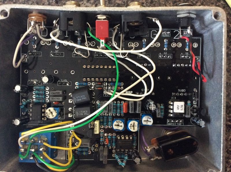
Sorry I missed it but yes they are just in series. There was plenty of room so I just used what I had on hand.
#11
Build Reports / Re: The Build Report of Why I Haven't Built Pedals Lately
April 11, 2016, 05:48:14 PMQuote from: 287m on April 11, 2016, 01:06:40 AM
where build docs for the drone?
just kidding.

Love it
#12
Build Reports / Dig dug 2
April 02, 2016, 03:07:39 PM
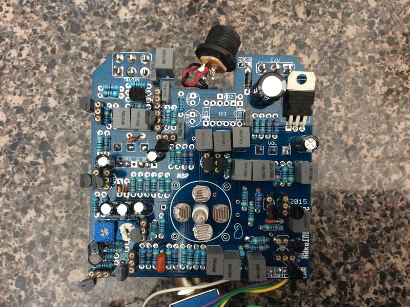
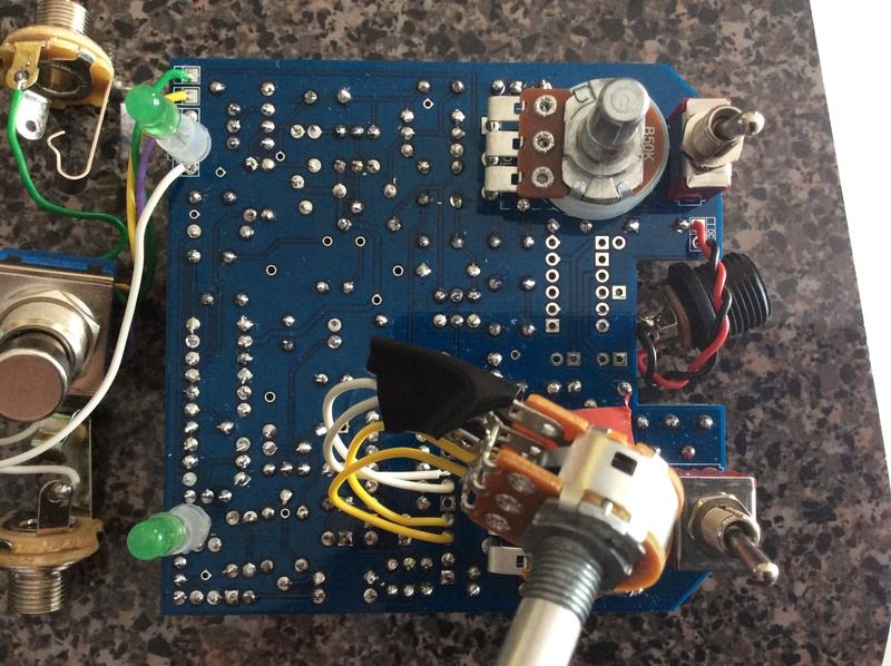
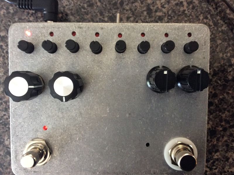
Wrapped this up yesterday. What a fun circuit to play with. It sounds awesome. I havent decided on artwork yet but am very pleased otherwise.


#13
How Do I? Beginner's Paradise. / Re: Dig dug 2 1p8t 2p4t ?
March 28, 2016, 04:59:50 PM
Well I feel stupid. I just laid them on there last night and thought, that sucks they look close. Guess thats what I get for doing it at 2am. I just put them on and like you said they are a little offset. Thanks
#14
How Do I? Beginner's Paradise. / Dig dug 2 1p8t 2p4t ?
March 28, 2016, 03:44:34 PM
This is a silly question but I don't want to screw it up. Which way do the 1p8t and 2p4t switches mount to the pcb? I havent seen any real indicator on the pot and the pcb just shows an arrow pointing down. Thanks in advance.
#15
General Questions / Harbinger sockets
March 27, 2016, 07:25:56 PM
I am finally ready to build my Harbinger. I wanted to get several projects down (over 20 now) so its time. I am wondering, those of you that have built this, is there any thing you wish you had socketed that you didnt? The power options I likely will (just in case I want to change it up later) but what about the bulb or the photocells? I havent really seen anyone say they socket these but it seems like if you burn a bulb it would be easier to swap.