News:

Forum may be experiencing issues.

Main Menu
Menu

Show posts

This section allows you to view all posts made by this member. Note that you can only see posts made in areas you currently have access to.

Show posts Menu

Messages - xorophone

#1
Quote from: midwayfair on December 23, 2016, 02:19:40 PM
The other side of the level pot is an inverting op amp input, so you won't hear anything there. But you have narrowed it down. Check, re-check, and triple check the components between the wiper of that pot and the op amp. Maybe you swapped a cap, or maybe you used a 120K where you should have used 12K, maybe there's a short to ground. But it's only a few components.
Quote from: jimilee on December 23, 2016, 06:50:26 PM
On the underside, where is says leviathan, make sure those aren't bridges. Check the whole board against the PnP.

I actually fixed it! ;D I'm extremely happy now because this was my first big pedal project and I really wanted to give it away for christmas!

I tried bypassing the LVL pot using a wire, and it worked fine so I decided to replace the potentiometer, which fixed the problem! The value was right so I just think it was broken. I'll have to measure it some day using my multimeter and find out what the problem was.

The tone pot isn't working great (I used a higher value and used a resistor to change the taper, but I think it just made it worse.), but I don't really care about that. Most of the change happens in the beginning of the rotation (the pot value seems to high and the taper is a bit crazy too), but I'm not even going to bother fixing it because I'll probably just break something else. It's not that important.

Merry christmas everyone and thank you so much for the help! :)
#2
I just did A BUNCH of audio probing and actually noticed that there actually is delay applied to the output-signal, but it's VERY low in volume. It's very hard to tell if the LVL pot actually makes any difference in volume, but I can still hear some delay when it's on 0, so I'm guessing it isn't working as intended. There's delay signal going in to pin 3 of the LVL pot, so maybe I'll have to try replacing it.

Quote from: xorophone on December 05, 2016, 10:43:29 PM
Another thing I forgot to mention is that I've soldered some resistors on 2 of the pots to try to change the pot value and/or the taper. I DID NOT know what I was doing but I decided to experiment with it. On the RPT pot I've soldered a resistor between lugs 1 and 3 and on the TONE pot I've soldered a resistor between lugs 2 and 3. This shouldn't really prevent the pedal from outputting the delay signal though, from my understanding.
This is something to keep in mind too. The LVL pot doesn't have a resistor on it.

What should I try next? I really want to finish this project now because I was planning on giving it away for christmas. In Sweden we celebrate christmas the 24th, so I'm under a lot of pressure. So please, if you have any idea, please tell me!

Merry Christmas!


Edit:
Quote from: midwayfair on December 01, 2016, 02:57:50 PM
There may be a couple places where you don't hear signal. Don't panic! You won't hear anything on the - input of an op amp.
This of course prevents me from probing the components between the LVL wiper and pin 6 on the op amp, which makes it a bit harder.
#3
Quote from: selfdestroyer on November 30, 2016, 10:32:55 PM
I would definitely add some pictures.

Cody

Here's some pictures:


Sorry for the bad underside photos. Please tell me if you need better pictures. I wanted to avoid having to desolder all the wires.

Quote from: midwayfair on December 01, 2016, 02:57:50 PM
When you audio probe, test:

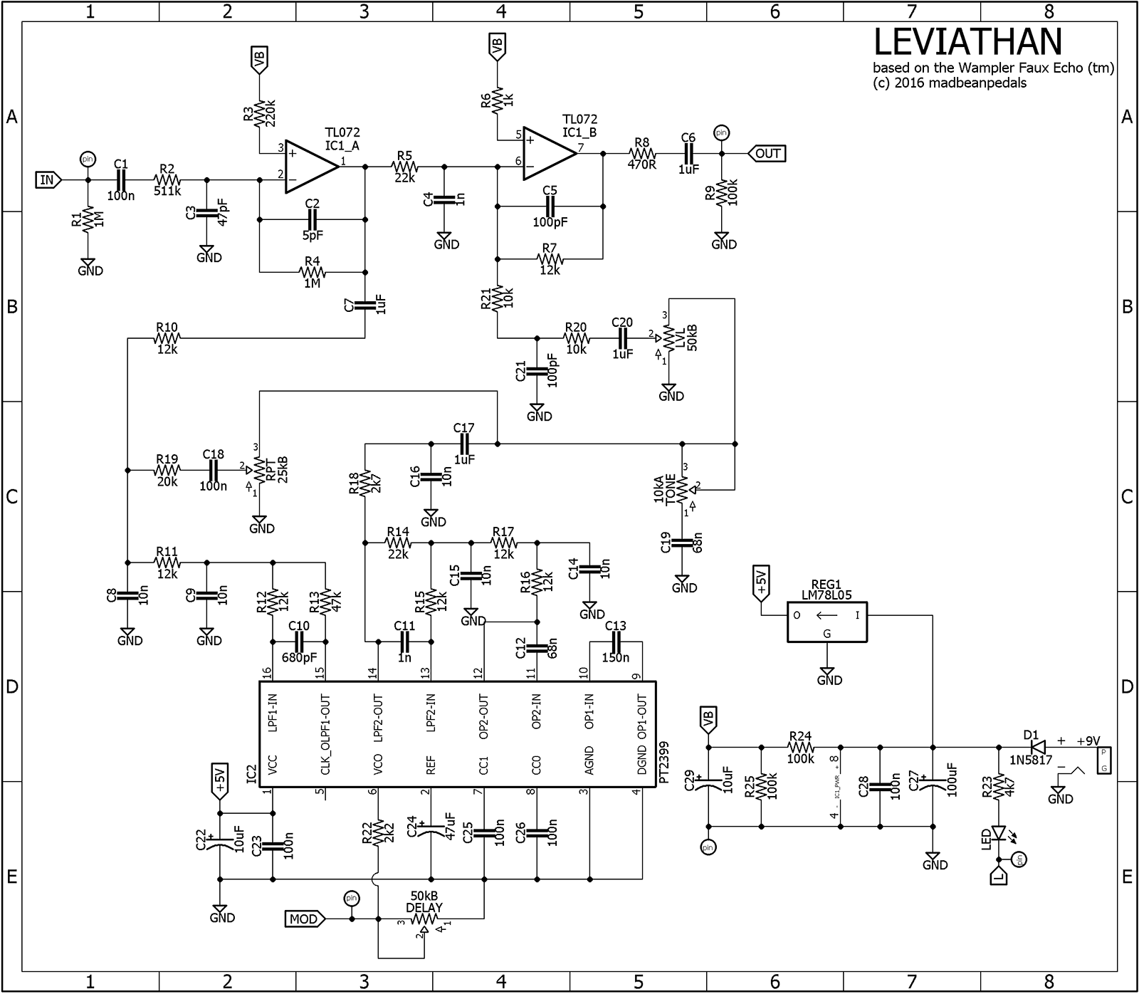
1. Both sides of R10
2. Lugs 2 and 3 of the repeats.
3. " " of the LVL

Start there, and check the components in between until you find where the signal is lost.

There may be a couple places where you don't hear signal. Don't panic! You won't hear anything on the - input of an op amp.

I started audio probing yesterday and I got some very interesting results.


  • There's both dry signal and delayed signal on both sides of R10. The dry signal SEEMS TO BE a tiny bit louder on the side facing the TL072 chip, while the delay signal on the side facing the TL072 chip is much quieter than on the other side. The repeat and delay pots affect the delay signal just like they should.
  • Lug 3 on the LVL pot outputs delay signal, but no dry signal.
  • Lug 3 on the RPT pot outputs delay signal, but no dry signal.

To me all of that information looks right. Where do you think I should continue probing? Which path should I follow? Sorry but I'm still pretty new to guitar pedal building so it's hard for me to know where it pays off to probe.

Another thing I forgot to mention is that I've soldered some resistors on 2 of the pots to try to change the pot value and/or the taper. I DID NOT know what I was doing but I decided to experiment with it. On the RPT pot I've soldered a resistor between lugs 1 and 3 and on the TONE pot I've soldered a resistor between lugs 2 and 3. This shouldn't really prevent the pedal from outputting the delay signal though, from my understanding.


Edit: Sorry for the horrible soldering by the way. ;) The solder kept travelling up the tip of the iron and landing on the tracks beside the pad. From my knowledge there's no solder bridges though. It was a lot harder soldering homemade PCBs than I expected.
#4
Quote from: selfdestroyer on November 30, 2016, 10:32:55 PM
I would definitely add some pictures.

Cody

I'll upload some pictures as soon as I have the time. :)

Quote from: madbean on November 30, 2016, 10:34:46 PM
Voltages look pretty good. You need to audio probe the circuit and find out if the PT2399 is getting signal and putting out any delay at all or if the signal is dying somewhere else.
Quote from: midwayfair on December 01, 2016, 02:57:50 PM
I know it's an official project, but it's helpful to have the schematic right here:


When you audio probe, test:

1. Both sides of R10
2. Lugs 2 and 3 of the repeats.
3. " " of the LVL

Start there, and check the components in between until you find where the signal is lost.

There may be a couple places where you don't hear signal. Don't panic! You won't hear anything on the - input of an op amp.

Thank you for the replies! I'll try probing it when I have time. Midwayfair, I'm guessing you mean the pots when you say "repeats" and "LVL". Is that right?

And what do you mean by
Quote from: midwayfair on December 01, 2016, 02:57:50 PM
3. " " of the LVL
?
#5
Hello!

I've recently finished my Leviathan delay from Etcher's Paradise. I etched a circuit board myself and it turned out good, but after soldering all parts the effect didn't work. I don't think there's anything wrong with the offboard wiring because the LED works like it should, the 3PDT wiring looks correct and the bypass works. When the effect is turned on the guitar signal goes through the pedal, but there's no delay applied. It's very hard to tell, but the signal might get a tiny bit amplified by the TL072 chip, so it seems like that one is working. It's of course really hard to tell when using a dynamic signal source though, so I'm not sure. I know it's impossible for you guys to troubleshoot it, but I just want you to tell me where I should start in the troubleshooting process.

Here's some information about modifications and stuff I've done to the circuit (please tell me if these could affect the circuit in any way):


  • I've used a 510k resistor instead of 511k (R2)
  • Many of the ceramic capacitors have been replaced with monolithic capacitors. For instance every 100pF.
  • I've used chinese PT2399 chips (and TL072 for that matter.) so there's a risk that my chips just aren't working.

I'm guessing the 510k resistor shouldn't make any difference, but I don't know about the monolithic capacitors, so please tell me if there's any problems with using those. Is there a way to check if my chips are working or should I just buy some real ones and hope they work?

I also checked the DC voltages on the chips using my multimeter, so here's that information:


PT2399:

1: 5v
2: 2.39v
3: 0v
4: 0v
5: 2.86v
6: 2.39v
7: 0.57v
8: 0.60v
9: 2.39v
10: 2.39v
11: 2.39v
12: 2.39v
13: 2.39v
14: 2.39v
15: 2.39v
16: 2.39v


TL072:

1: 4.26v
2: 4.28v
3: 4.17v
4: 0v
5: 4.25v
6: 4.28v
7: 4.28v
8: 8.58v


It looks perfect to me, but please tell me if there's anything wrong with it or if I should measure something else.

If you want pictures or something I can post that too. Just let me know!
#6
Quote from: sominka on November 01, 2016, 10:21:52 PM
Cut  a piece of your toner paper and tape it onto the pcb etch image which will be on your plain paper build document.  Put the whole page back through your printer and reprint.
Hope this helps.

Oh! Now I understand! That's a smart solution. Hopefully it doesn't get to thick for my printer to handle, though. I'll try it.

Thanks! :)
#7
Quote from: selfdestroyer on November 01, 2016, 08:39:37 PM
Quote from: xorophone on November 01, 2016, 08:17:08 PM
Do you mean I should open the PDF-file in Adobe Acrobat Reader and then print the whole page?

That's the easy way is to print the whole PDF page that has the PNP on it.. or use GIMP like Brian suggests. I uses HP Presentation paper so printing a full page is not a big deal to me. But if your using blue or expensive paper then I can see this being a problem.

Cody

I'm using toner transfer paper, but it's not too expensive, so I guess it'll have to do until I find a better solution.

I don't really understand what Brian mean, so if any of you could explain I'd be really happy. As I said previously, the DPI of "Leviathan_PNP.psd" is already set to 300 in Gimp. Might be easier to use Photoshop, but I don't have it.

Thanks for the help!
#8
Quote from: madbean on November 01, 2016, 08:32:47 PM
Print the page from Acrobat, cut the PNP to size and tape it over the PCB image and print again to the same page.

Or if you can open the PSD file in Gimp, set the DPI of the image to 300.

Sorry but I don't really understand the first part.

The DPI is already set to 300.
#9
Quote from: selfdestroyer on November 01, 2016, 08:02:26 PM
If you open them in Adobe Acrobat Reader and print to 100% no scaling you should have no problems. What specific layout are you trying to print? I can test it for you.

Cody

I'm trying to print the Leviathan delay. (I built it on perfboard first but failed.)

There's a file in the ZIP called "Leviathan_PNP.psd". That's the one I've been trying to print (after exporting it using gimp.) The picture in the PDF-file looks like it's the right size so I tried using an online pdf image extractor to download the picture, but it was the same size as the psd-file.

Do you mean I should open the PDF-file in Adobe Acrobat Reader and then print the whole page?

Yes, I'd love if you'd test it for me!

Thanks!
#10
Hello! I want to etch something from Etcher's Paradise, but the black/white pictures used for the toner transfer are much bigger than they're supposed to be. If I print it with 100% size it covers almost the whole A4 paper. How do I fix this? The images seem to be 300dpi and my printer is 600 dpi, if that makes any difference. Note that they're big before printing as well.

I'm guessing just scaling it will solve it, but which size (or percentage) should I scale it to?
#11
Quote from: thesmokingman on October 27, 2016, 02:27:18 AM
if you build a dyna comp or ross clone, source the metal can 3080 ... it is one of the few mojo items I feel really lives up to the hype.

Oh okay, I will! I've always wondered what those round metal things have been, so thanks for clearing it up for me!
#12
Quote from: jkokura on October 26, 2016, 10:26:57 PM
That sounds like the Ross Comp to me. Any sort of 'classic comp' that utilizes a CA3080 is probably what you're looking for.

Jacob

Thanks! I'll take a look at it.

If anyone has any more recommendations I'd love to hear them, so I can compare them.
#13
General Questions / Compressor with a lot of character?
October 26, 2016, 08:40:43 PM
Hello! I'm looking for a compressor build that will give me that vintage, slightly distorted sound. One that really has character.

Which ones do you recommend?
#14
Thanks everyone for the replies!

In this case the 11k resistor was just an example, so I don't have a schematic to show you.

Buying the exact values is pretty hard here in Sweden. I don't have any stores I can go to if I want to pick up a specific value and you often have to pay for shipping when ordering online, which is of course not nice when you're just ordering a few different values.

I have a basic understanding of the different parts of a schematic though, so I'll probably be able to tell the bias resistors apart from the rest of the circuit. If the bias resistors for some reason are 11k, changing both to for example 10k shouldn't, from my understanding, affect the circuit at all (as long as both of the resistors are the same value.) And if they're different values on the schematic you'd just have to calculate the ratio and use other values.

Thanks for the links too, Jon and Dave. Those will be handy.
#15
Hello!

Let's say I for example need an 11k Ohm resistor in a project. I haven't got any 11k, only 10k and 1k.

How do you guys deal with this when using circuits designed by someone else? Editing the PCB layout would be really hard if you don't have the project file.
The only thing I can think of is putting two resistors (10k and 1k) in series on a really small board and then solder that board to the 11k resistor pads. I guess that would work, but it would look really bad.

Any other ideas?