
So, stepping away for a while really helped. Turns out I had the wrong value resistor hanging off one of the legs of Q4. I'd put a 470 ohm resistor where a 470k resistor belonged. Turns out that 3 orders of magnitude makes a big difference. Thanks for the help, This thing is rocking hard.
- Welcome to madbeanpedals::forum.
This section allows you to view all posts made by this member. Note that you can only see posts made in areas you currently have access to.
#1
Tech Help - Projects Page / Re: Help debugging a really quiet wolfshirt
August 26, 2012, 04:58:19 PM #2
Tech Help - Projects Page / Help debugging a really quiet wolfshirt
August 26, 2012, 02:24:43 PM
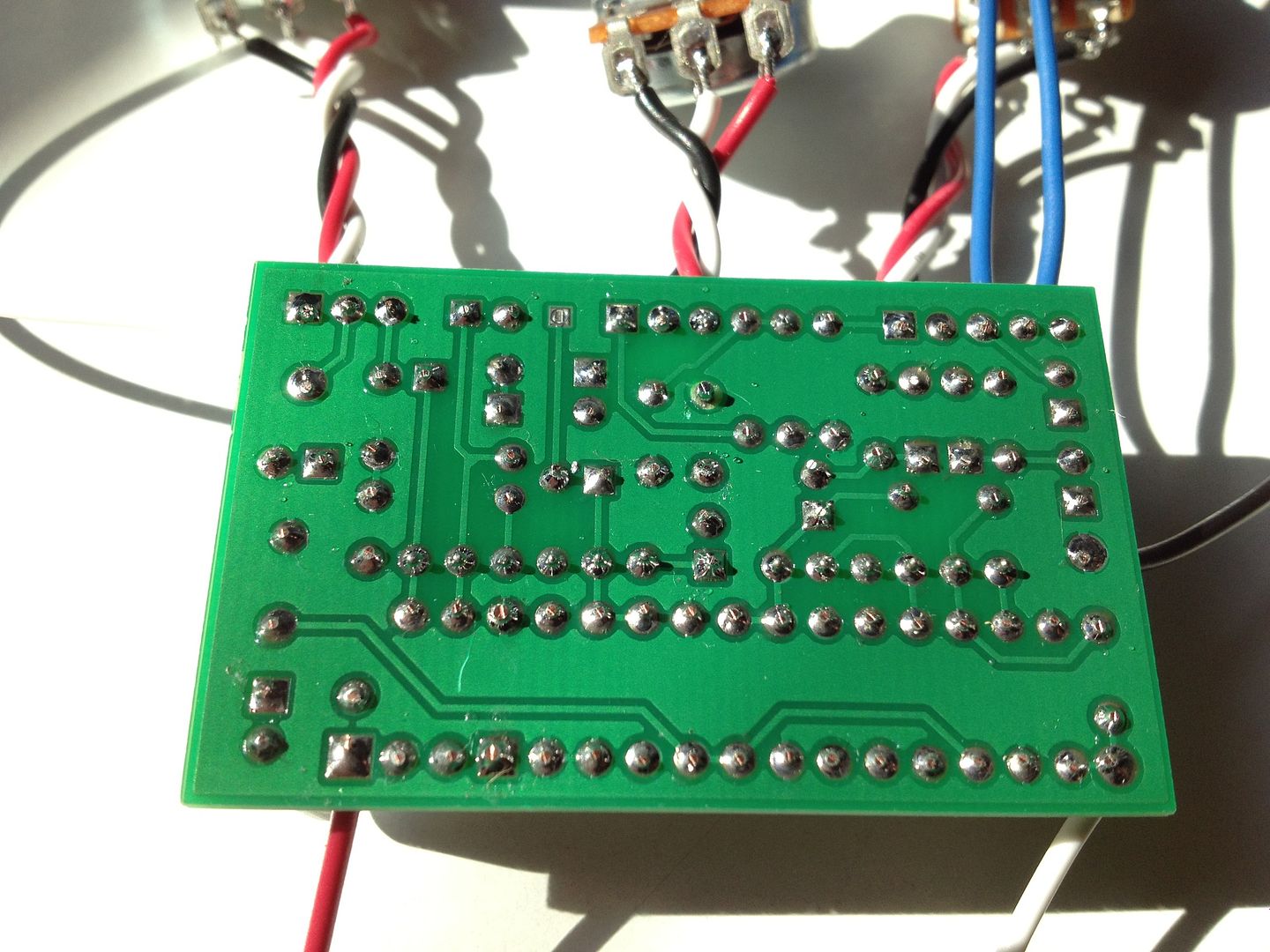
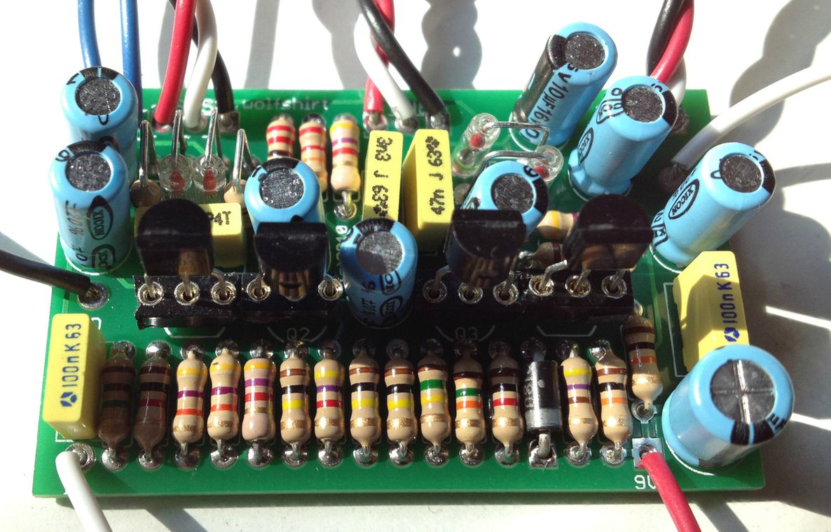
I populated a pre Jan 2012 Wolfshirt board (using 2n3904 trannys) this morning and attempted to rock it before boxing it but found that the output while heavily distorted and octaved was very low. So, I checked the underside for solder bridges but when I didn't find any, I broke out the trusty DMM and audio probe to see what I could find. Here goes.
Tracing the signal with the audio probe, my guitar signal was clearly louder than unity (by a bunch) at Q1, moving to Q2 I found that it was also much louder than unity and at Q3 the signal was louder but also distorted. Q4 is when things got really quiet. I could hear the distorted/octavey signal but just barely.
The signal was strong and distorted up to the diode side of R17 but on the junction of R17 and R18 the signal gets somewhat quieter and a little muffled. Signal is also loud on the Collector side of C10 but I got nothing at the node of C10 and tone pot lug 3. The level at lug two of the tone pot was quiet and fuzzy. The level at the collector of Q4 was the same as the output volume at lug two of the volume pot.
I thought that C10 might be bad so I replaced it to no avail.
Below are the voltages I collected. Again, using a pre Jan 2012 fabbed board and 2N3904 trannys.
Q1 e=144mv b=.77v c=2.3v
Q2 e=1.7v b=2.3v c=7.22v
Q3 e=195mv b=.82v c=7.2v
Q4 e=6.45v b=7.2v c=6.47v way too high right?
I'm out of ideas, I can't understand why the voltages on Q4 would be so high. Below are a couple of pictures in case they help. I checked the orientation of my electros and they look right. What am I missing? Any thoughts are greatly appreciated.
#3
Tech Help - Projects Page / Re: Aristocrat Volume Question
June 13, 2012, 04:44:09 PM
Thanks for the tips, I think this is a great sounding circuit and I may have misspoke when I used the term "dimed". 
In any event, I'll try some of your suggestions. Thanks as always.
In any event, I'll try some of your suggestions. Thanks as always.
#4
Tech Help - Projects Page / Aristocrat Volume Question
June 11, 2012, 07:27:39 PM
Just wondering if there is a way to get more volume from the Aristocrat. I know I can add a larger gain pot to get more gain but I'm just hoping to make the thing louder. Seems like I have to have it dimed to get just above unity. I'm using a single sided V4 Aristocrat. Thanks again for all the help.
#5
Tech Help - Projects Page / Re: Aristocrat problem revisited now with voltages. Success!
May 17, 2012, 06:03:24 PM
Jacob,
Before I posted last night, I realized that I wired the channel 1 pot to the LED pads and fixed that but still had the same problem on BOTH volume pots. Discouraged, I posted here and went to bed.
I read your post and decided to go over everything again and in doing so realized I had indeed wired BOTH volume pots incorrectly lugs 1-2-3 did not match up with the appropriate pads on the board so at full volume the pot was shorting (if I'm figuring it right). The pisser is I managed to wire BOTH volume pots that way. None of the other 8 million pots on the Aristocrat were wired incorrectly.
I fixed the wiring and wouldn't you know it, it worked just as it should. It's pretty noisy but I'd wager that's because it isn't boxed up, I've got alligator test leads running all over hell and gone, and I've got an electric fan running on my bench (for solder fume abatement)
In any event, thanks for the help. In the last few days I've successfully debugged two pedals that had been bothering me for a long time.
#6
Tech Help - Projects Page / Aristocrat problem revisited now with voltages. Success!
May 16, 2012, 06:03:24 PM
Finally got back to an Aristocrat build (Version 4 build docs, single sided ver 3.5 etch from same V4 build document) I started some time ago and it seems to be mostly working now that I've gone over it again but one problem still persists. I should preface the following info by letting interested parties know that I did all the testing/troubleshooting without boxing up the circuit as instructed. That said, everything seems to be working except that when either of the volumes (Ch1 and Ch2) are dimed, the volume cuts out completely.
If it helps, here are the IC voltages.
IC2
Pin 1 4.37V
Pin 2 4.38V
Pin 3 3.84V
Pin 4 0.0V
Pin 5 4.25V
Pin 6 4.30V
Pin 7 4.23V
Pin 8 8.50V
IC1
Pin 1 4.30V
Pin 2 4.31V
Pin 3 3.85V
Pin 4 0.00V
Pin 5 4.20V
Pin 6 4.20V
Pin 7 4.18V
Pin 8 8.50V
If I can add any more info, I'm happy to do so....I'm just lost for ideas.
#7
Tech Help - Projects Page / Re: Loophole problem revisited
May 15, 2012, 06:21:01 PM
I had a look at a couple Youtube demos of the Loophole and realized that both the LEDs illuminate in record mode. So excited to have this up and running, thanks for the help. I've had a string of failures and it's nice to get something working. I love your stuff!
Next up, my aristocrat debug. Got a little lab set up at home so I can get good pictures and voltages. Boom.
Thanks again!
Next up, my aristocrat debug. Got a little lab set up at home so I can get good pictures and voltages. Boom.
Thanks again!
#8
Tech Help - Projects Page / Re: Loophole problem revisited
May 15, 2012, 04:52:49 PM
Brian,
Thank you so much for the reply. A little more tinkering and I'm able to record and playback AND detune. When the detune is off, everything is dandy and I've noticed that the detune only works a short time. What a relief.
The only problem remaining is that when I record a loop, both LEDs light up. I've checked my wiring and everything seems to be kosher but I should add that I included the safe switch....does that matter?
#9
Tech Help - Projects Page / Re: Loophole problem revisited
May 15, 2012, 03:19:19 PM
Okay, sat down and did more probing and found out that the regulator only overheats if the Dtune switch is on. looks like the bottom leg of the regulator gets shorted to ground through the 22 ohm resistor near the Dtune switch. Is that what's supposed to be happening? If so, why is that regulator getting so darn hot? About to throw in the towel on this one.
#10
Tech Help - Projects Page / Loophole problem revisited
May 14, 2012, 03:34:18 PM
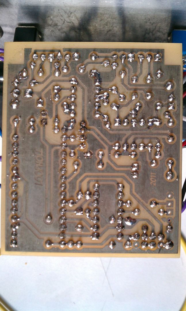
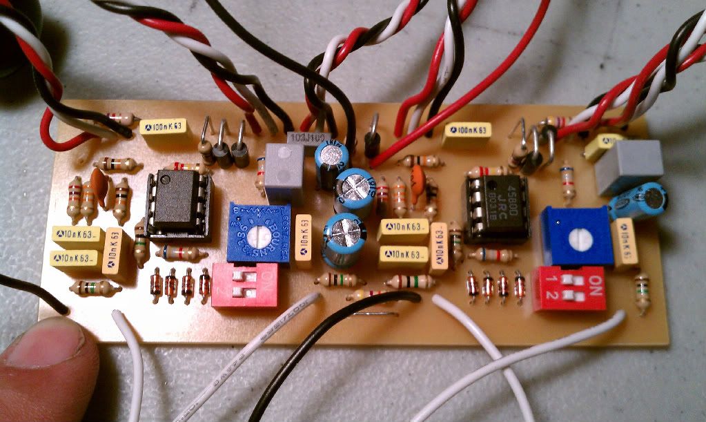
I started debugging my loophole several weeks back but got sidetracked and just got back to it this evening. It seems the power regulator is getting really hot no matter how it's oriented in the socket. When I supply power, I read 9.18 V at whichever lead happens to be in the upper most socket (assuming you're looking at the board as it's laid out in the build documents) The other legs of the transistor will vary in voltage depending how they are oriented.
I took the power regulator out and I began poking around looking for continuity and found there was continuity between the middle and lower transistor socket (forgive me, I can never keep straight EBC especially since I've flipped this tranny around so much). Looking at the schematic, I got the impression that there shouldn't be continuity there.
I removed C17 and C6 in the off chance that they were bad and perhaps were acting as dead shorts to ground but when I pulled them out, there was no continuity through them and there was still continuity between the two lowest pins of the socket.
Is my thinking completely screwed, am I reading the schematic incorrectly? It should also be noted that I get signal when it's bypassed and when it's plugged in to power (even with the hot ass regulator) pedal will pass signal and I can increase the volume with the volume knob. There is no record or playback function which doesn't surprise me.
I'm really at a loss for where to go here so any help would be appreciated. I've included a picture in case there is a solder bridge or something I've missed.
#11
Tech Help - Projects Page / Re: Loophole problem....
April 22, 2012, 11:15:08 AM
MB,
I'm not sure what brand I'm using, I got the regulators from a helpful soul over at BYOC because the originals I bought were way too big. I'll try flipping the regulator around and see if I get different voltages. The only thing I did differently was add the safe switch so that I don't accidentally record over my loops.
What voltages should I be seeing on the specific pins. I'm guessing 9v, 5v and maybe something else?
#12
Tech Help - Projects Page / Loophole problem....
April 21, 2012, 09:06:05 PM
I built a loophole and the regulator is getting super hot. Like, too hot to touch hot. It should be noted that I'm using a 78L05 rather than the 7805. My last several pedals have been big failures so I'm hoping someone might be able to point me in the right direction as pertains to troubleshooting.
When I measured voltages at the DC jack, it was only running at 4.5v or so which is peculiar. I would have expected to see 9v there and 4.5V at the regulator.
Thanks in advance.
When I measured voltages at the DC jack, it was only running at 4.5v or so which is peculiar. I would have expected to see 9v there and 4.5V at the regulator.
Thanks in advance.
#13
Tech Help - Projects Page / Re: Aristocrat troubles...
March 20, 2012, 01:17:02 PM
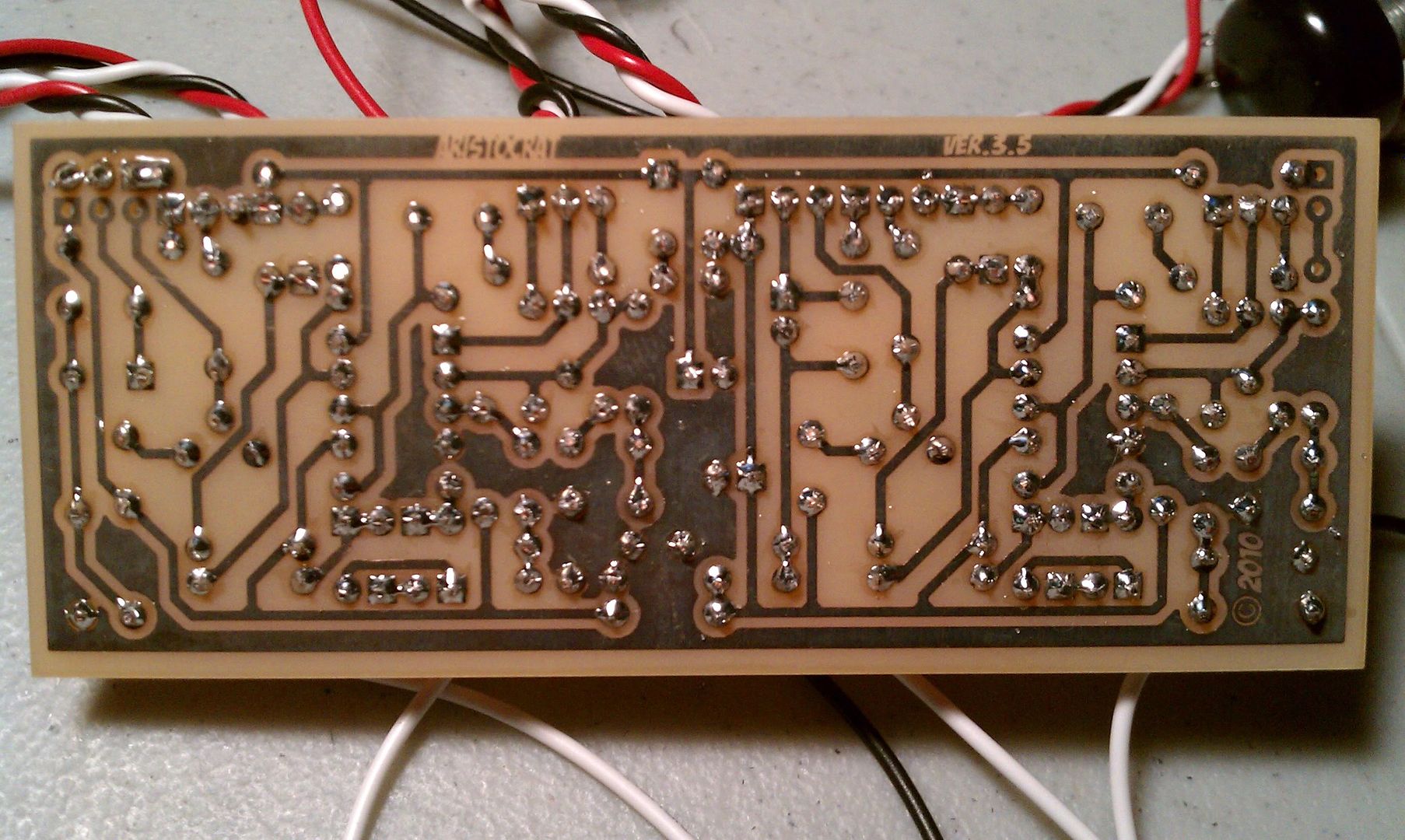
I went to the lab and messed with the Aristocrat for a while again yesterday, took some voltages and such but left the sheet with my notes on it elsewhere. I'll get those posted as soon as I can. That said here are a couple pictures along with a description of what's going on.
I think part of my problem, originally was that I was testing with a weak battery. I replaced it with one reading 9.12V and I could hear a noticeable difference in how loud the circuit was. Weird thing is, it only seemed to help one channel and after just a few minutes of testing, the voltage on the battery was about 8.55v. Makes me think something is wrong.
Also, touching any of the lugs of the channel two tone pot made things louder. I use pot condoms so I held the pot in one had (not touching the pot case) and touched one of the lugs and it got louder. So, only one channel is mostly working. Everything on channel 2 save for the volume pot dieing at full rotation is okay. I don't remember all the voltages but I do remember that with a fresh battery pin 8 was only getting about 8v. There was 5.6 milivolts on pin 4 and the rest were about 4 or so volts if memory serves.
I tested the unit by connecting the 9v in to the + side of a battery, the G1 pad to the negative side of the battery and then connecting the lugs of a jack to the appropriate place on the board, i.e. sleeve to the ground point on the lower left of the board and the input to the input of ch 2. I hope that's consistent with the functioning with the pedal.
Thanks again, I think my next step is to get it back into an enclosure and go from there.
Do lugs 4 and 7 of the 3PDT have to be permanently jumpered like 7 and 8 are?, I'd never seen that done that way before so I figured I'd ask.
#14
Tech Help - Projects Page / Re: Aristocrat troubles...
March 19, 2012, 01:31:52 PM
Yep, it's me, Joe.
On my way to the lab to take another stab at the Aristocrat. Will post voltages and pictures when I get back this evening.
Thanks!
On my way to the lab to take another stab at the Aristocrat. Will post voltages and pictures when I get back this evening.
Thanks!
#15
Tech Help - Projects Page / Re: Aristocrat troubles...
March 17, 2012, 04:38:25 PM
I will definitely get voltages next time I get to my bench, probably won't be till Monday though.
Anyone know what kind of voltages I should be seeing on the ICs?
Thanks again.
Anyone know what kind of voltages I should be seeing on the ICs?
Thanks again.