
Chewie, we're home
- Welcome to madbeanpedals::forum.
This section allows you to view all posts made by this member. Note that you can only see posts made in areas you currently have access to.
#62
Open Discussion / Good to hear from Strongbad again
April 08, 2015, 11:09:17 AM
Don't know if anyone else noticed a new SBemail went out on April 1st.
#63
Open Discussion / Tayda 1900H clones OK to use?
April 06, 2015, 08:59:01 AM
I'm working on a project that has LOTS of pots. Tayda's price for the 1900H clone is really cheap. Are they even worth buying? This will be a project that will be living on my workbench, not a pedal board. Still, if they don't at least have inserts, I'm not interested. Anyone have experience with these?
#64
Build Reports / Pennyroyal Chorus... in ((((STEREO))))
April 05, 2015, 05:26:39 PM
This gif kind of sucks. To see a better version, in much higher resolution, click here. There are playback controls down in the lower right. You may have to scroll around your screen to find them.


Quite a while ago, Stomptown hooked me up with a v1 board of his excellent Pennyroyal along with a bunch of parts and values I didn't have on hand. I told him I was going to build it into a 1590B. He said, "Think twice about that. It's going to be a tight squeeze." I said, "How hard could it be? I build into the 1590LB. I can take it. And, I think I'm going to add a daughter board and make it stereo." Jon was right. It was a bigger challenge than I expected. In fact, if it weren't for the Kobiconn compact jacks he gave me, this wouldn't have been possible! The spacing between the board and stomp ends up being critical. Drilling had to be perfect. Thankfully, I decided to do an effect cancel rather than true bypass for this one (more on that later) so a compact DPDT was in order.
Converting one of these to have a stereo output is not hard at all. I found all the info I needed for the mod at Tonepad. There is an etchable layout for a daughter board that you can use to tap into any small clone circuit. I decided to come out with my own layout in the interest of getting it as compact as possible. It uses 1/8w resistors, or the compact 1/4w ones Chromesphere sells. I used Paul's just because I like them. If there is interest in my daughter board, I can make it available to MB members as an OSH Park share.


Because the effect has a stereo output, I decided not to attempt true bypass. Aside from the fact that I wouldn't have been able to get it to fit into the 1590B, I didn't feel it was the right move for this pedal. For starters, I would have had to use a 4PDT stomp, which don't have the most sterling reputation for reliability. Also, even with 4 poles, I would have been splitting the input passively to the two outputs in bypass. This would have been way more problematic than just keeping everything buffered and canceling the wet paths. The buffered signal isn't entirely transparent, but it's dang good. Either output can be used for a mono chorus, and when using both, I get a fantastic stereo sound. So far, I've only run it in stereo through a little stereo chip amp I built based on the Ruby circuit. I run that into my Egnater 2x12. I'm not getting any weird phase issues in mono or stereo. It just sounds great, and I highly recommend the mod.
As for the aesthetic, I kind of went literal with the name. I don't know why, it just seemed like it would be a fun thing to try. Since I've started messing with the resin, I've tried to think of creative new ways to incorporate it. I thought it would be cool to embed a real penny and illuminate it from underneath. It worked, but it's only visible in low light. Oh well. It's pretty easy to tell audibly when the effect is engaged.
It's kind of funny, but I dug through probably hundreds of pennies to find the one that I felt had the most character! You'd be surprised how much variation there is. I noticed that pennies from the '60s seemed to have a deeper, more dimensional impression. This one was just somehow special, so I used it.
There are actually two ribbons embedded in the resin. There's a wide blue one over a narrower gold one. I should have tested them with water before coating them. What happened was once the resin hit the blue, it just kind of disappeared against the black! It's there, and you can see it in bright light, but it's just way darker. Too bad, because it was such a cool look before the color shift. My 13-year-old daughter actually helped me pick out the colors. We looked at tons of ribbons before deciding on these.
There are multiple resin pours on this. The first pour didn't fully cover the ribbons. I was chasing drips on both pours and it shows. I didn't get that seamless edge that I was hoping for. Oh well. I also did two pours for the jewelry bezel that the penny sits in. The first pour was a shallow pour (after drilling for the LED). The point was to give the penny something clear to sit on so light could show from underneath. The second pour was to dome it. The LED is filed all the way down to just above the anode/cathode and it pretty much butts right up against the penny. I have it cranked bright. I'm probably flirting with disaster using a 390r. If it burns out, the only thing I'll be able to do is mount another one underneath it to shine through it.
There was one final resin pour to mount the LED and affix the bezel. I lined up the bezel, taped it in place, flipped the enclosure, and poured resin just around the base of the LED. I noticed that it would fill up the hole but then after a few minutes the level would be back down again. I did this three or four times and then just left it, fearing that resin was going to leak out all over and ruin the top. As it turned out, it did leak, but just to the edges of the bezel, so it was the perfect way to firmly affix the bezel to the top. Happy accident.
jmwreck gets credit for the knobs. I saw them on his SWAH V3 build and knew I had to have them. Here's a link to the seller. I was a bit disappointed when all of the knobs arrived scratched up because they were all thrown together in one bag. So, pour some resin on 'em! That's right. I did tiny resin pours on the tops of the knobs. It really diminished the scratches and makes them look neato.
I got the idea for the ground bus once I saw how nicely the in/out/power jacks lined up with the stomp switch. It was actually pretty easy to do, and I love the way it looks. Kobiconns ftw! To be honest, I'm not a big fan of having my signal jacks sticking way out of the enclosure. I would have spaced them in with some washers, but I couldn't do it in this instance without the lower output jack running into the stomp switch. It looks like there's tons of space there, but there really isn't!
If you look really close, you'll see one little electro is a bit out of place on the right side of the board. That's C10. I have its positive leg hanging off the board connected to a flying lead. That's where you tap into the circuit to cancel the effect.
My 17 year old son, Josh did the photography for me. It was really fun to work with him on it. Here's a pic of him shooting for the rotating gif. This was a series of 91 pictures. I used a cheap light tent, a $6.00 lazy susan, foam core and white paper. I made hash marks around the circumference of the turn table and used a toothpick as a reference pointer. Incidentally, juansolo gets credit for getting me interested in light tents. This one is a cheapie, but it collapses down, which is cool. I still need to get some decent lights.

Thanks for looking and thanks for reading.
#66
Open Discussion / saw this in Seattle today (stupid reality TV related)
April 03, 2015, 06:41:19 PM
I realize it speaks to shallowness in me, but my wife and I really like to watch this stupid show. We live a few hours south of Seattle and were up there for a couple days just the two of us. The last few times we've been up there, I've checked to see if any of the crabbing fleet were in the harbor at Ballard. This time I found a website that actually shows the location of all the boats. When we saw that our favorite boat was there, we drove down and walked around until we spotted it. It's smaller than we thought. Still cool to see though.
#67
Build Reports / Padawans!!
March 22, 2015, 06:02:32 PM
My friend Bret (aka "Echobret") asked me a while back if I'd be willing to put on a maker clinic at his coffee/donut shop teaching pedal building basics. I thought that sounded like fun, so I put together a simple LPB1 project and walked a few interested souls through the process of building it.
As it turned out, Jon (aka "stomptown") was able to show up and get involved too. I think I speak for both of us in saying it was a blast. Neither of us feel like we've arrived when it comes to electronics knowledge, but it was really satisfying to teach some beginners the basics according to what we know. It was kind of "everything I wish someone would have shown me when I was starting out" kind of a thing. It was a lot of prep work on my part in doing a simple PCB layout (should have had Jon handle that. He is an Eagle layout rockstar), putting parts kits together, drilling cases etc. But it was all worth it and I hope we're able to do something like this again.
We taught the basics of reading schematics and how they relate to the physical parts & PCBs, using layout diagrams, how to solder, how 3PDT switches work and why we wire them the way we do, parts sourcing advice, test rigs, etc. and then we kind of shared some of our methods for doing stuff. We also gave them a handout with a bunch of links. Of course MB was at the top of the list. I'm hoping we'll see these guys introducing themselves here soon.
The project was super dumbed down in an effort to guarantee success. It worked! Everyone's builds fired right up and you won't believe the gut shots are all from noobs.
I highly recommend doing something like this if you ever get the chance. It was really, really fun.
Here are our Padawan learners. Notice Jon's pedalboard in the background. It's like an art gallery That's also his test rig sitting on the "bench"
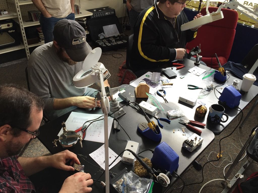
Here are all three beginners' gut shots. I don't know why I didn't have the presence of mind to take any exterior shots. They are plain white with an LED, stomp, and knob. I'm super proud of these guys and super thankful for Jon's partnering with me in making this happen. And Thanks Bret for coming up with the idea, purchasing all the parts, and allowing us to use your rad coffee/donut/record/music gear shop as a venue.
As it turned out, Jon (aka "stomptown") was able to show up and get involved too. I think I speak for both of us in saying it was a blast. Neither of us feel like we've arrived when it comes to electronics knowledge, but it was really satisfying to teach some beginners the basics according to what we know. It was kind of "everything I wish someone would have shown me when I was starting out" kind of a thing. It was a lot of prep work on my part in doing a simple PCB layout (should have had Jon handle that. He is an Eagle layout rockstar), putting parts kits together, drilling cases etc. But it was all worth it and I hope we're able to do something like this again.
We taught the basics of reading schematics and how they relate to the physical parts & PCBs, using layout diagrams, how to solder, how 3PDT switches work and why we wire them the way we do, parts sourcing advice, test rigs, etc. and then we kind of shared some of our methods for doing stuff. We also gave them a handout with a bunch of links. Of course MB was at the top of the list. I'm hoping we'll see these guys introducing themselves here soon.
The project was super dumbed down in an effort to guarantee success. It worked! Everyone's builds fired right up and you won't believe the gut shots are all from noobs.
I highly recommend doing something like this if you ever get the chance. It was really, really fun.
Here are our Padawan learners. Notice Jon's pedalboard in the background. It's like an art gallery
That's also his test rig sitting on the "bench"
Here are all three beginners' gut shots. I don't know why I didn't have the presence of mind to take any exterior shots. They are plain white with an LED, stomp, and knob. I'm super proud of these guys and super thankful for Jon's partnering with me in making this happen. And Thanks Bret for coming up with the idea, purchasing all the parts, and allowing us to use your rad coffee/donut/record/music gear shop as a venue.


#68
Open Discussion / Who says you need guitars, pedals, amps to rock!!
February 25, 2015, 11:12:50 AM
I feel like Jack Black must have been involved in this in some way.
I think the girl in the back right corner has the best job. Floor tom, snare, cymbals. It adds to the Bonham effect.
I think the girl in the back right corner has the best job. Floor tom, snare, cymbals. It adds to the Bonham effect.
#70
Open Discussion / NAD!! Leslie 147
February 21, 2015, 07:40:43 AM
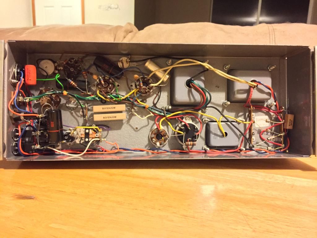
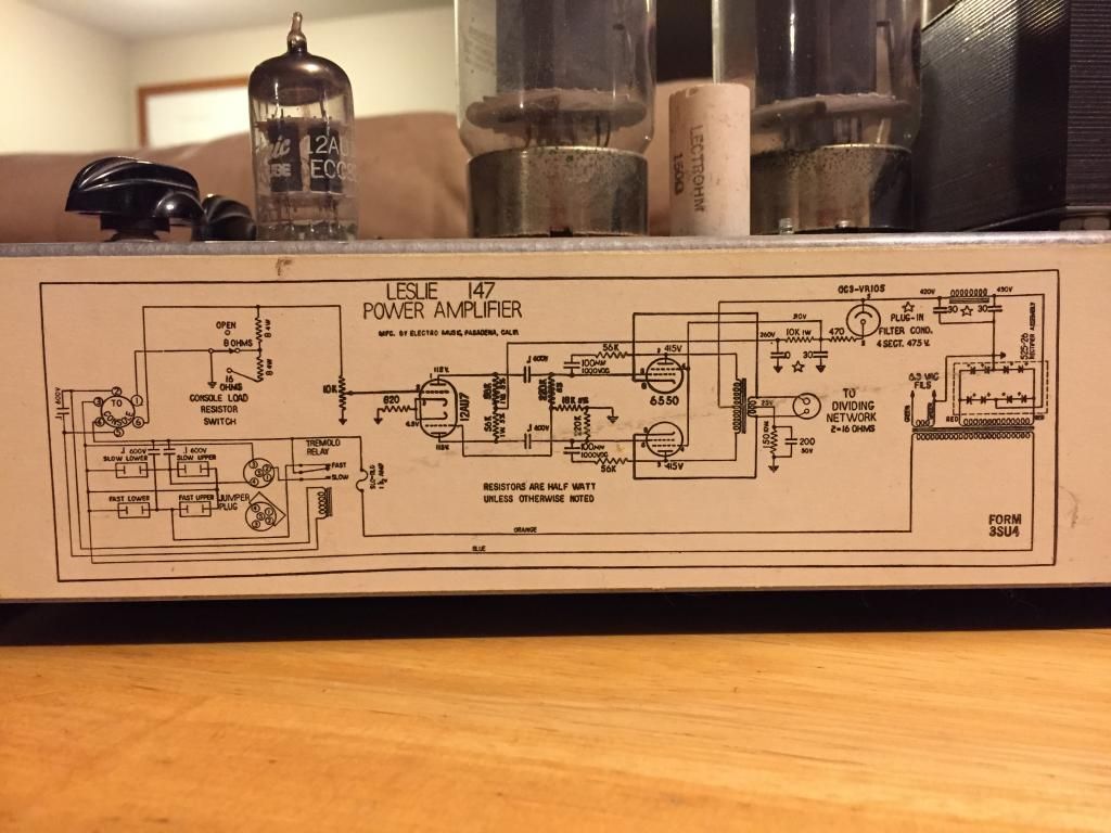
I scored a beautiful, like new Leslie 147 amp for use in converting my passive Leslie 45 tone cabinet into a 2 speed amplified Leslie. I also scored a couple 2 speed motor stacks for the project. There is a pretty long story about how I acquired it. If you're interested in that, or if you want to know about my Hammond M3/Leslie 45 ongoing project, you can read all about it in my thread in the DIY area.
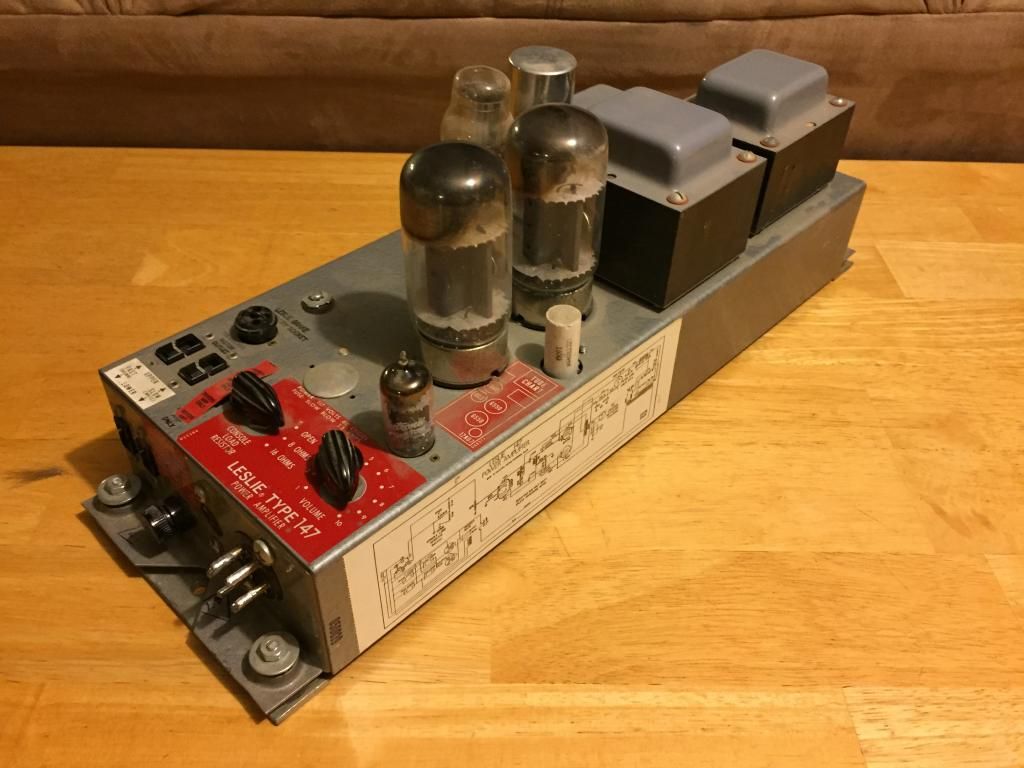
I really love these knobs. If anyone is into casting knobs, I would be willing to loan one of these out to be cast. I think they look fantastic. Also, that volume pot starts at 1 and goes to somewhere between 11 & 12! Someone tell Nigel. Maybe thats the Jon Lord setting.
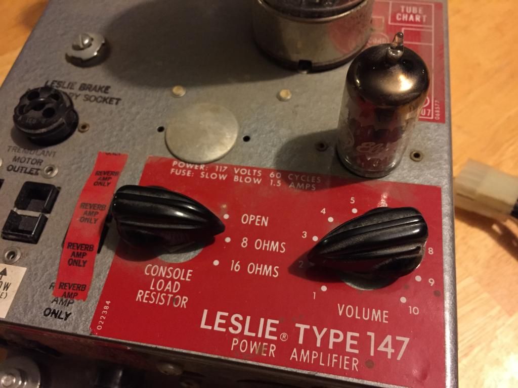


I really love these knobs. If anyone is into casting knobs, I would be willing to loan one of these out to be cast. I think they look fantastic. Also, that volume pot starts at 1 and goes to somewhere between 11 & 12! Someone tell Nigel. Maybe thats the Jon Lord setting.

#71
Open Discussion / Catalinbread Zero Point???
February 07, 2015, 03:25:57 PM
This looks/sounds like a really nice flanger. I love the concept. Is it just me, or is the name ringing a bell?
#72
Open Discussion / Reamping, impedance matching, and other questions/musings
February 05, 2015, 09:55:04 AM
I have never tried reamping, but I'm intrigued with the idea of capturing a guitar part, but still being able to mess with it later, out of the box. I've thought about it off and on for a while now. I just read the Tone Report article on it and that sparked me to investigate a DIY reamp box. I found the LINE2AMP kit, and it looks pretty interesting. I'm thinking it would be fun to come up with my own take on this very simple circuit. I wonder what other cool things could be added to make this even more useful.
I find impedance to be a dark and mysterious thing. I would love to be able to have more control over it than just having my signal buffered or unbuffered. A few years ago, I built a variant of the electra distortion. I found it to be a VERY good sounding circuit IF it was interacting directly with my guitar. But I also discovered that it sounded terrible with a buffer in front of it. I kind of want to make this circuit available, but it has such a split personality. I would love to be able to get it to sound great no matter what's in front of it. So, I thought about putting a buffer at the front end and then filtering off the highs, but I have a feeling that it's more than just a little tone sucking.
I wonder what would be involved in building an impedance matching circuit, similar to what's at the front end of a lot of mic pres. Would it require multiple transformers? And, would I end up with something like a reverse buffer, that would allow pedals that like to be hit with high impedance to sound good later in the chain?
Is anyone here experienced with reamping? If so, did you find that the amp responds to the signal as if a guitar were plugged into its input?
Anyone else interested in developing an ultimate reamping box?
#73
Open Discussion / NSSD
January 22, 2015, 05:11:46 PM
New soldering station day!
You guys failed miserably at talking me out of buying the Hakko FX-888D soldering station. So far, I'm really impressed with it, although I feel like I've betrayed an old friend in replacing my fully functional Xytronic 379. I can't fully account for that part, but it definitely appears to be a step up. For one thing, the base unit is about half the total footprint and about twice the weight. I imagine that's the transformer. (The label on the hakko iron shows 65w at 26v, where the xytronic is 45w at 120v) The cable is about a foot longer, smaller diameter, and quite a bit more flexible. It's also detachable. I think there are other hakko irons that are compatible with this station. I like that it has temp presets too. There is a great selection of tips for these too, and the prices seem really reasonable, and everyone says that hakko tips are really good. The iron stand is metal and has a nice weight.
I had read enough reviews to know that the weakness of this iron is in the unintuitive 2-button control. It's especially bad in that you can inadvertently enter a calibration mode and totally screw it up. I just read and re-read the manual until I felt confident that I understood how to run it. It's honestly pretty simple to run. The weirdest thing so far is that my xytronic doesn't have any temp markings, only wattage markings for the dial, so I never really knew what temp I was soldering at. It will probably take a while for me to settle on a couple go-to temps. Right now I have 3 presets dialed in. One for low temp idling, just above 400F, one at 550F, and one at like 650F. I'll see how those work.
Here's what it looks like next to old faithful:

Here's a comparison of how much smaller the cable is compared to the xytronic.

#74
Open Discussion / Hakko FX-888D: talk me out of it
January 19, 2015, 12:49:51 PM
I'm really happy with my Xytronic 379 45w station. I'm only on my second tip in about 5 years of continual use, including all of the time it's been left idling overnight. I have a bad tendency to leave it on. This is my first iron since abandoning the radio shack fire starter I used on my first TS-808 kit. Why do I want to replace it? I don't have a good reason, and someone needs to talk me down.
Maybe it's the blue and yellow. Some people hate it. I think it looks fantastic.
Actually, after reading tons of reviews and watching youtube vids, I'm pretty taken with the quality of this station, as well as the Hakko tips. I like the idea of presets, although I know where to turn the dial on my Xytronic for the different things I solder, so that may not be an actual feature. I also like that Hakko considers this thing completely user serviceable. The manual includes exploded views of the iron and base station with part numbers for everything. That's not something you see often these days. It would also be nice to have 2 irons so one can be portable. I hate extricating my station from my workbench setup.
I think the Hakko must be a good one or there wouldn't be counterfeits on allied express.
Also, I have this $100 amazon gift card that's been burning a hole in my pocket!
HELP ME!!
If you are using this setup, I'd love to hear your opinions about it. Or, you could tell me why I should just stick with the Xytronic that's still working like new.
#75
Open Discussion / NMD
January 19, 2015, 11:48:19 AM
I actually got this a couple weeks ago. It was a gift from my mom. The brand is "Lakeside" and from what I can tell, it was a lower end of Lyon and Healy. It also seems that they stopped making bowl back mandolins in about 1915.
I think it's pretty cool that it's so old. It's beautiful and decently playable. It badly needs a restring, but it does tune up. Tuning machines aren't the best, but they all work. I've used much worse. I hate the thought of replacing them because they look so cool. The fretboard and frets show zero wear and the top is nice and flat.
The back seems to be mahogany and rosewood. Honduras and Brazilian? Of course!! (Who knows?) I love the look of the back. I also love that the pickguard is inlaid into the top. Neato.


#76
Open Discussion / Always buy your breadboards from Tayda...
January 15, 2015, 09:53:06 AM...and make sure you get the see-through kind so you can identify where the missing contacts are


#77
Open Discussion / ...and down the rabbit hole we go
January 01, 2015, 05:49:55 PM
I got an arduino uno as a late Christmas present. Yay! Now I have a whole bunch of learning to do. At the very least I want to be able to make a PWM motor control and build a pickup winder.
Other ideas?
Other ideas?
#78
Open Discussion / Anyone seen these enclosures?
December 31, 2014, 07:24:20 AM
I had never heard of Rixen enclosures before. These are spendy but cool.
#80
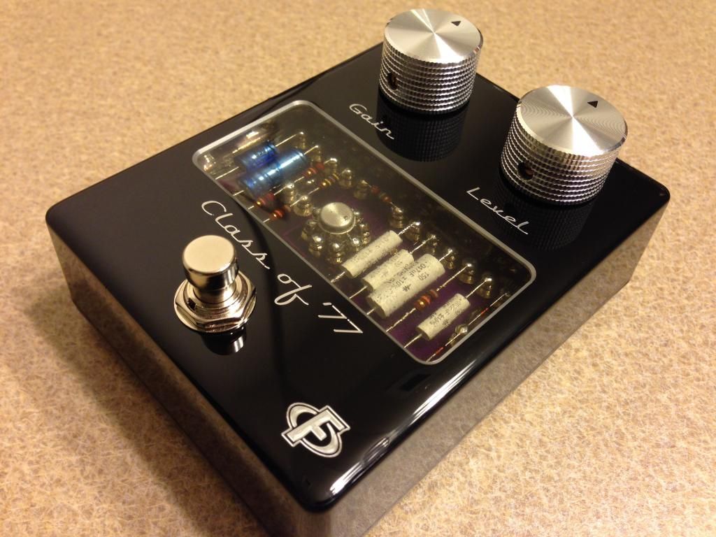
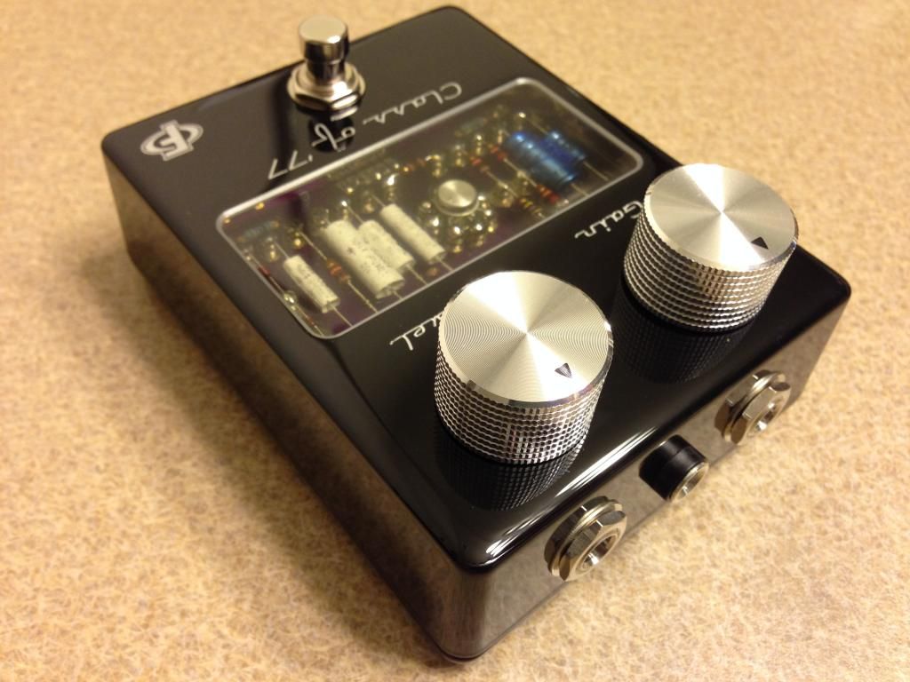
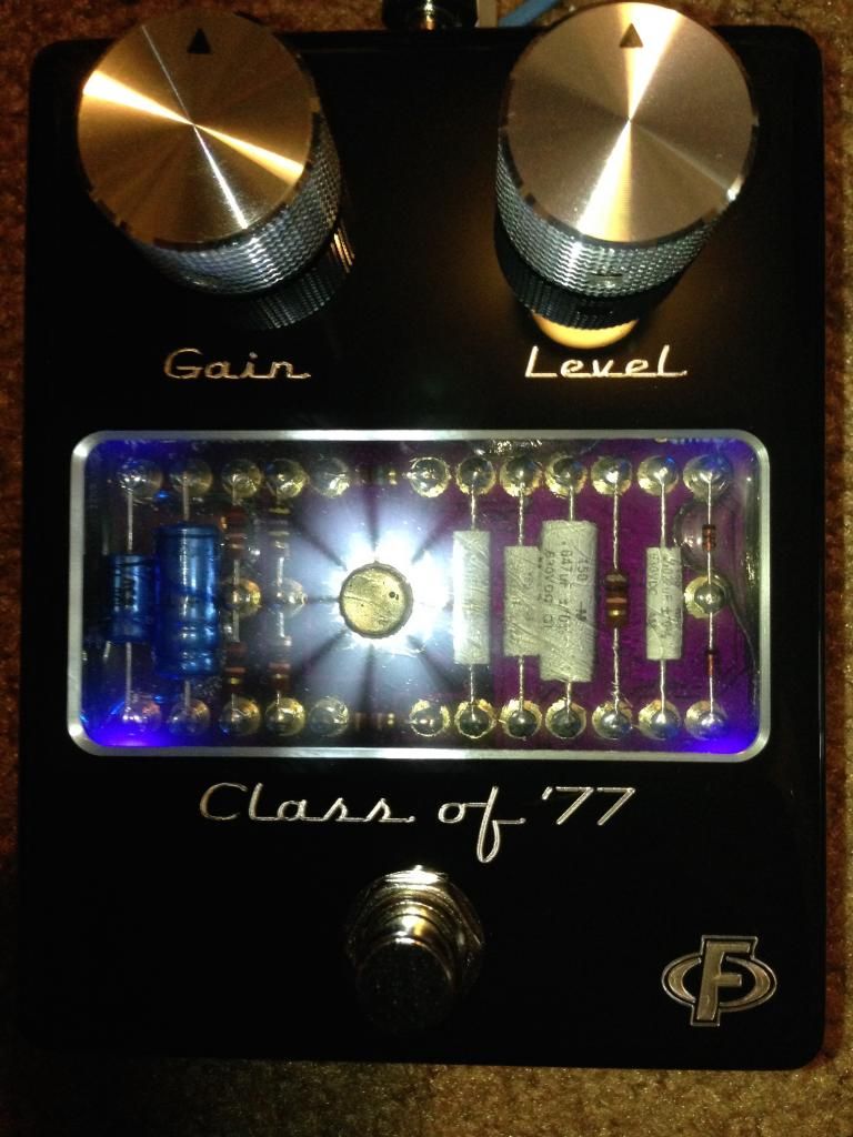
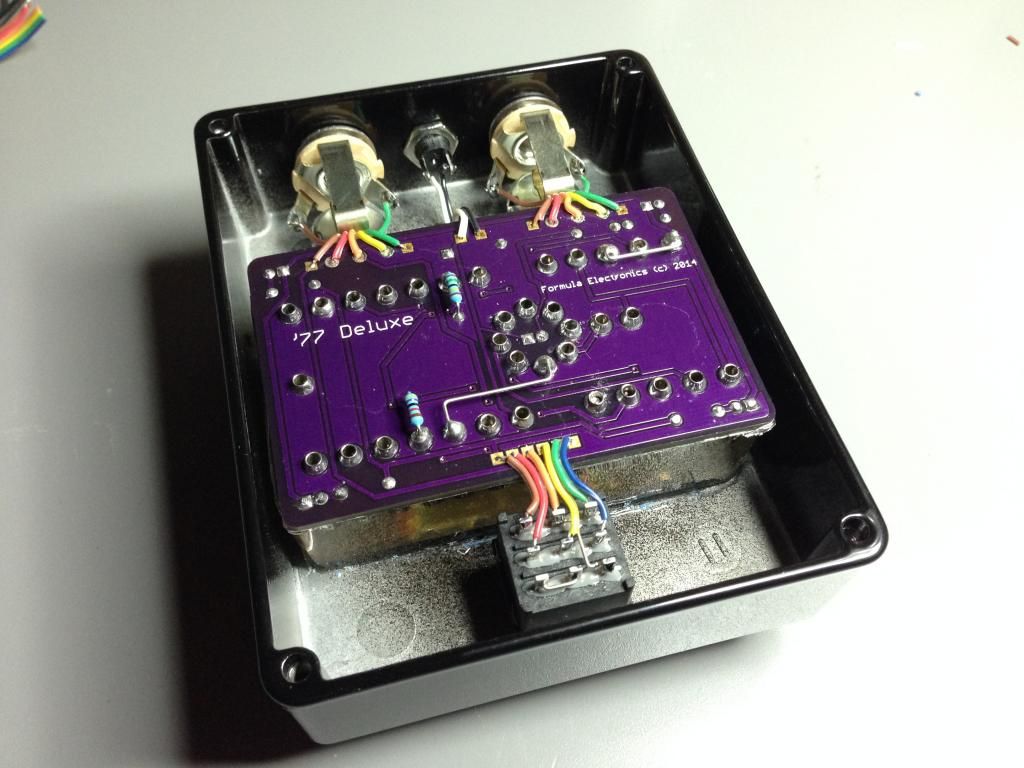
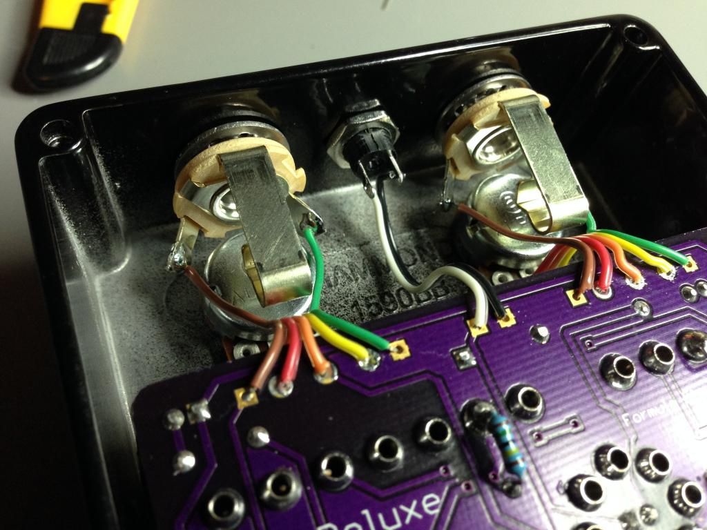
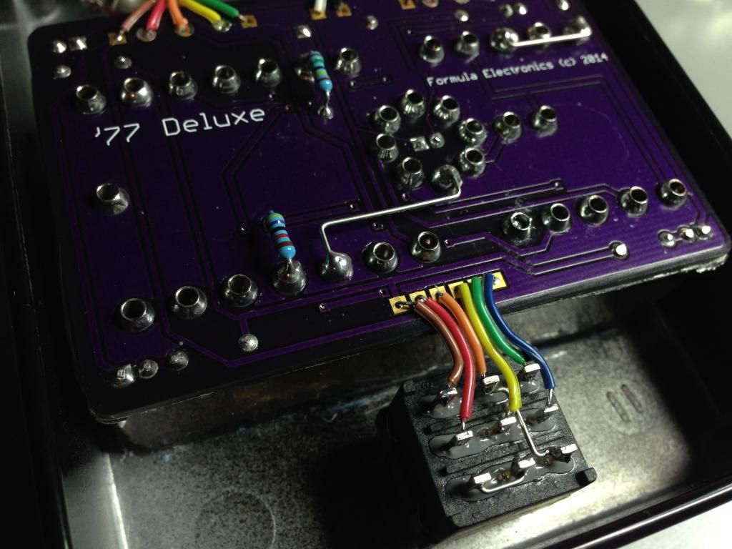
Build Reports / Class of '77
December 24, 2014, 02:54:05 PM
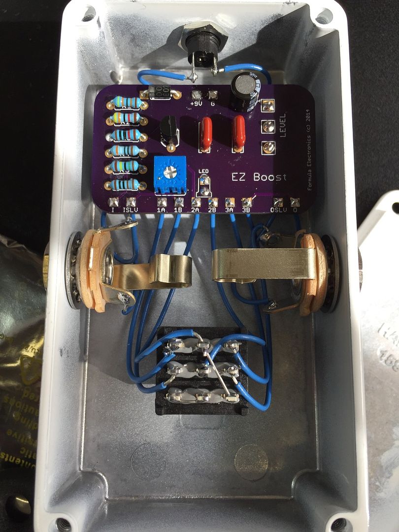
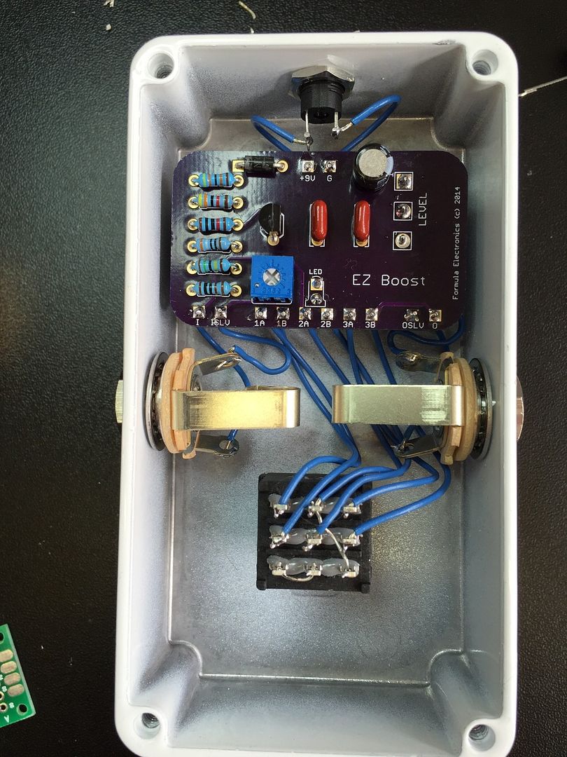
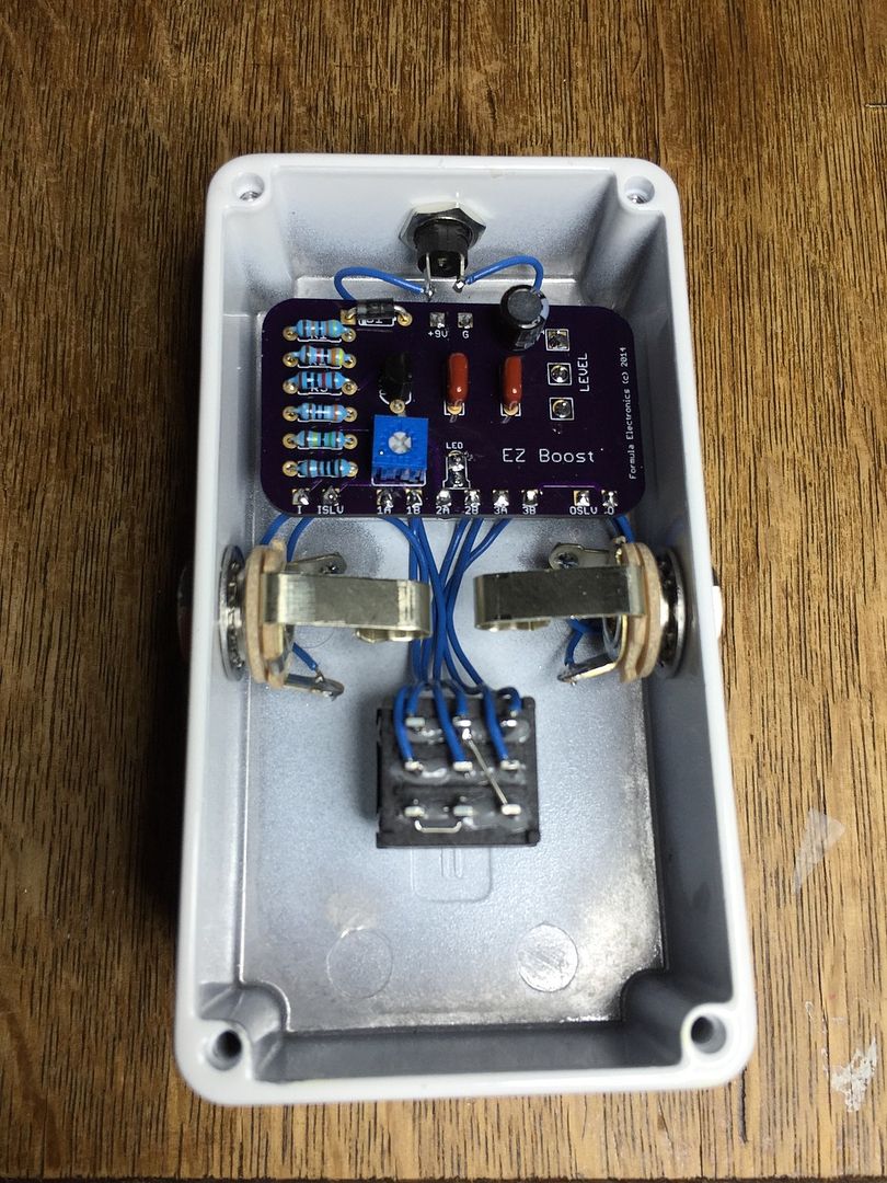
Here is my latest labor of love. This was going to be my fall contest entry, but there were holdups in the process, so it didn't make it. I'll post the pics up front and add the TLDR section later for those who don't care to read a novel.
TLDR section:
For a long time I've wanted to build a pedal with a window into the guts but I couldn't think of a way to do it without ugly hardware around the top of the pedal. Once I got into messing with jeweler's resin, (aka envirotex) I realized I could try to encase an entire PCB in resin, put that inside the case, flow resin across the top, and that would give me one monolithic chunk of clear that would hold itself in place.
I had also been thinking of doing a PCB layout that would look something like the guts of a vintage tube amp. I thought it would be cool to make a board using gigantic pads that would be sized to accept turrets. So, I came up with this hybrid PCB that has some through-hole components and some turret mounted components. The goal was to lay the board out with the visual aesthetic as the primary concern, regardless of what that would mean for efficiency. Hence, this thing is a via-fest!! It's a terrible layout, but it looks so cool!
Even though I went for as simple a circuit as I could think of, it was still a crazy puzzle to figure out. I spent tons of time measuring, drawing, visualizing to get this to look right and still fit in a 1590bb. For the most part, I really lucked out with the way everything fit. One thing that I didn't account for was the size of the shoulders on the turrets. The OD of them was too big to sit side by side in the ring of turrets that makes up the opamp portion. So, I had my good friend Eric machine them down! Since then, I've figured out that I could have just cut them above the shoulder and let them sit on the little collar halfway up the turret. Oh well. It worked!
Eric is also the guy who did the machining for me. All of the cutting and engraving on the top was done by him using a CNC mill. I wasn't able to capture in pictures how good and jewel-like it looks.
There were many nail-biting moments in this build:
- seeing if the idea of soldering turrets to a PCB would even work
- firing up the circuit through my test rig for the first time. It didn't work!! I was terrified that I'd fried the metal can opamp. It takes so much heat to solder to turrets. I used a heat sink clamp, but still. It turned out (after MUCH studying the schematic and my layout) that there were two missing ground connections on the PCB, hence the jumpers on the bottom.
- firing it up AFTER I had scrubbed the PCB, worrying again that liquid may have done damage to the opamp
- making such a massive block of resin and wondering if I would get the amount right so it wouldn't overflow when I put the circuit into it. Also, wondering if I would get crazy amounts of air bubbles with no way to release them.
- firing it up after encasing it in resin!! It was a massive relief to hear it come to life. By that point I had put in a ton of work. By the way, I used a soap-making mold to cast the resin. I was lucky to find one exactly the right size. I had to chop down the depth a bit.
- flowing the final resin on the top. Black is SUPER unforgiving. I was also worried it might leak down inside the window and make a mess of all of my wire. I ended up using my hero, blu tack to hold the block in place while the top cured.
- drilling the resin out of the holes. Thankfully, no lifts!
- Wiring! I kept telling myself it was stupid to use ribbon! Every time I stripped a wire I was afraid I would break it. Every time I soldered, I was worried that the insulation would melt and go out of shape. There would be no turning back with this because all of the solder joints on the board were in resin.
- Being afraid that I would scratch the top while I was wiring.
- Finally firing it up after it was all together. So glad it works!!
There were also some firsts in this build:
- My first gooped board!!
- my first pedal with a window into its soul
- my first machined pedal
- my first turret/pcb hybrid board. I have to admit I thought it was my idea until I was later inside a vox amp.
- my first ribbon cable build
- my first use of carbon comps and axial caps in a build
I also want to say that I went into this understanding the many impracticalities of the build! I know I won't ever be able to replace the electros. I know there is more susceptibility to RF noise. I know the pcb layout is really bad from a practical standpoint. Hopefully it's clear that none of that was the point. This is just whimsical.
OK, so has anyone guessed the circuit? I will PIF one of these boards and a couple of those pretty blue Phillips caps to whoever can guess the circuit AND which parts in this pedal were purchased at radio shack.
DON'T POST YOUR PIF ANSWERS HERE! I'll make a thread in the PIF section and paste a link here
http://www.madbeanpedals.com/forum/index.php?topic=19001.0
nieradka guessed it! Knobs are Rat Shack. I've had these knobs for a couple years just waiting for the right build. For me they just really go well on this build. Who would have thought? Circuit is a '77 grey spec OD250. I needed something simple to make the concept work. This fits the bill and it's a great sounding circuit.