News:

Forum may be experiencing issues.

Main Menu
Menu

Show posts

This section allows you to view all posts made by this member. Note that you can only see posts made in areas you currently have access to.

Show posts Menu

Messages - Jamiroking

#1
Mods / Re: Some Moodring mods, pretty useful!
November 29, 2017, 08:20:50 AM
I know this is an old thread but I ended up printing up some PCBs from the moodring schematics and have been toying around with some of these mods.

Using the notes by timbo_93631, Boba7, and neandrewthal, I came up with the schematic changes here. This is the first time I've ever did any mods beyond just basic routing switches so any questions or advice is welcome. I'm still waiting to receive a parts order to finish this build.

Input Level
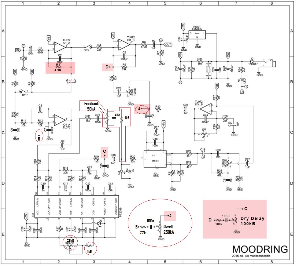
I implemented the original input level pot but it just wasn't that usable for me, especially because if you wire the pedal in buffer bypass, it's always on. So the two options are permanent boost (buffered) or a volume jump when engaged (true bypass). This doesn't work for my need since it's going to be joining a host of other pedals on my board and I don't need it to pull double duty as a drive pedal. I ended up just reverting back to madbeans initial R3 value of 470k.

New DWELL Knob (reverb feedback)
When I wired it up with timbo_93631's replacement DWELL knob after adding his FEEDBACK pot, the reverb was very faint. I wasn't sure if it was the placement of the A route or the additional cap that he put on lug 3 of the 250kA, but when I moved the route back to the original location (right after R30) and got rid of the 100n cap he added, my reverb came back to life. I thought about moving the B route to after the IC but I was happy enough with my results.

Dry Delay Mix
After axing the Input Level pot, I had an extra hole drilled in my enclosure that needed filling and neandrewthal's idea of putting a dry mix of the delay signal on a knob sounded like the best option. I took his idea of copying the RING knob with a bigger resistor and breadboarded with the components I had around.

With the parts I had around, this configuration allowed me to pretty much kill off the dry signal when the pot was at 0% and have a very good standalone effect volume all the way up to 100% if I kill off all the reverb mix (RING knob)

I only had 100nF and 4.7uF caps and the 4.7uF took way too much off the signal. I would have liked to try the 1uF similar to the RING but the 100nF sounded clean to me.

Likewise the next values of resistor and pot I had were 382k and 500kA and both killed way too much of the signal. Going down to a 50kB made it impossible to get rid of the dry delay signal.


Mods Summary
So I think what's left is a bunch of knobs which are very usable and the possibilities of using the pedal in a variety different ways

  • SPACE (Pre-delay) - 25kB for longer values. I think this could actually be even longer. I accidentally wired up a 100kB and there were some cool things you could do with it if you wanted.
  • DWELL (Reverb Feedback) - The new knob by timbo_93631 made a little more similar to bean's original
  • MOOD (Reverb Tone) - this is still stock
  • Dry Delay Mix - with RING all the way down, you have a delay pedal!
  • FEEDBACK (Delay Feedback) - same as timbo_93631
  • RING (Reverb Mix) - this is also stock
  • Slam Switch - still waiting for my DPDT but I will probably short both FEEDBACK and RING pots like Boba7 mentioned but shorting the dwell could be useful too

#2
For those other newbies that might be experiencing the same issue, it looks like I ended up toasting one or both of the transistors on the board. I bought two new ones and my build is back up and running like normal. Since I hooked it up to 12v, the charge pump ended up pushing 24v through board.

Lesson: DO NOT HOOKUP THE QVIBE TO 12v.
#3
Quote from: diablochris6 on October 03, 2017, 12:21:27 PM
... I would just wait for the Superring or find another neat reverb with predelay *cough* Tesseract Reverb *cough*.

I didn't know about the tesseract but it sounds really awesome. I would have waited for the Supering but I just don't have the real estate on my pedal board for the 1590BB those would take unfortunately.

I may split the difference and try my hand at laying out the board and order a Ping to tide me over.

Quote from: zombiesonore on October 03, 2017, 12:30:39 PM
We PM'd but he never reply to my offer and it's been almost 3 weeks I think.
I will sell it to you if he doesn't answer to my last message by the end of the week.

Thanks a lot Zombiesonore! Obviously they get first dibs
#4
General Questions / Discontinued double layer boards
October 03, 2017, 12:04:18 PM
Sorry if this is covered somewhere else in the forums but I couldn't find it.

I know Haberdasher is making the single-sided boards for discontinued products but unfortunately I'm really interested in building a Moodring and that PCB has multiple layers.

It looks like I could order a small batch of boards here
https://www.pcbway.com/?ngaw=33&campaignid=793796577&adgroupid=44014088391&feeditemid=&targetid=aud-292348526782:kwd-18635313&loc_physical_ms=9004067&matchtype=p&network=g&device=c&devicemodel=&creative=196555801627&keyword=pcb%20prototype&placement=&target=&adposition=1t1&gclid=CjwKCAjw6szOBRAFEiwAwzixBfrQdxS9Pj1Mq0Siu-E-f11gRj9gJmp_v9lnPPQlRIRlrrLMwtEArBoCgMYQAvD_BwE

I was wondering if Brian has any materials for this kind of thing (eagle files, etc) or if it's up to us to reproduce the pcb layout if we wanted to handle it on our own. OR if it's frowned upon in general.

I've never used Eagle before but I'm just looking for a way to get the Moodring! Not trying to rip off Brian's awesome work. I just want his sweet, sweet reverb :)
#5
update:It looks like I also might have hooked it up to a 12v power supply during the time it was shorting if that helps thinking about possibly damaged components. :-[
#6
Thanks Brian. That's all I needed to hear.

You probably saved me a few afternoon's worth of frustration and 2 failed builds :)

#7
I've been building out a smaller version of my pedal board and was looking at building an Afterlife with the Sensitivity mod as well as a Bacon Bits. Does anyone have any experience fitting these boards into the small, square 1590LB enclosure?

Ideally I'd like to still have the controls accessible (not just internal trimpots) but mini pots are fine.

Is this being too greedy?
#8
Tech Help - Projects Page / Q-Vibe not pulsing anymore
October 01, 2017, 03:08:54 PM
Hey guys,

I had to reopen the QVibe that I built a while ago to replace a burnt out LED it was working completely fine unboxed and even when I boxed it up but all of a sudden the lamp no longer pulses. I unboxed it again and its still the same.

The main thing I can think of is while I was boxing it, I overtightened the speed knob, shorting it against the led bezel. Is it possible that I fried something on the board that would result in LFO not oscillating?

I haven't been building in a long time and when I did, I never had to probe for voltages so I don't really even know where to begin. It doesn't help that this wasn't the cleanest build in the world :/

Thanks guys for any help you have.
#9
Thanks everyone for your responses so far. I'm glad to see this thread get so much action since I think it's something that really needed to be addressed. Even if we don't come to a consensus, its really useful just to read everyone's opinions to get a general feel for the viewpoints that are out there.

I think its been especially useful to hear from jkokura since your move to having a web presence is one of the prime examples that jumped out in my mind. But also hearing how a lot of big name builders have pedals that are basically clones of others sorta complicated the matter for me.

Since the pcb artwork is the copyrighted material, I was thinking I would probably just design my own 1) so I'm not using brian's boards in the ones I'm distributing and 2) so I get some experience doing it and can add that to my bag of tricks.

My other issue is, while I would love to mod circuits to feel more "in the right", I feel my knowledge isn't quite that deep and any mods I've come up with are purely superficial (eg. true bypass toggle on the sunking or creative LED/switching designs) That being said, a lot of the attentino my pedals have been getting has to do with the creativity and effort that I put into the aesthetics of the pedal. For instance, yes, people can buy the commercial version of the krankosaurus, but it won't look road worn and westerned themed and that's one of the main reason people want mine. To me, this conversation gets even more complicated considering that we aren't building standalone circuits but ones that are part of a larger product.; much harder than if I was going to be selling clones in plain metal enclosures but I think also evidence that I'm not trying to undercut anyone and am offering something unique.
#10
So with all my recent builds, I've been having a lot of people start asking me to build stuff for them.

Now, I value my time since I'm a pretty busy guy so I don't want to be building stuff at cost, especially since I spend a lot of time and effort on the aesthetics of my pedals. But on the other hand, I don't want to do anything to disrespect the community and especially Brian who has put so much work into this and given so much to all of us.

So basically, what should I do to be most respectful to all the intellectual property that I've been working off of so far?
#11
General Questions / Re: Quadrovibe Demo
March 08, 2012, 10:38:37 PM
I was planning on making one but then I broke my Qvibe cramming it back in the box so now I have to fix it first.....
#12
Open Discussion / Re: stumbled across a spare 1590bb
March 05, 2012, 11:21:12 PM
one more knob hole and you got a krankasaurus
#13
Build Reports / Re: Quadrovibe (AKA Sea Sick)
February 28, 2012, 01:20:19 PM
Haha yeah thats a but of masking tape since I didn't have any heat shrink big enough. Don't worry, it has since been replaced.
#14
Build Reports / Re: Quadrovibe (AKA Sea Sick)
February 28, 2012, 12:40:50 AM
Thanks a lot Guys

I don't have a camera so I'll see if I can find one to borrow to do a demo. At the very least, I can do an audio demo but I think it would be nice to show the trim pot adjustments as well. They play a pretty significant part in this pedal.

Although some others suggested mounting them externally, I decided it wasn't really worth it since they really interact with each other and you have to play around and compensate any changes to one with the other
#15
Build Reports / Quadrovibe (AKA Sea Sick)
February 26, 2012, 06:27:05 PM
I finally brought myself to box up the Quadrovibe I wired up a while ago. It was a pretty intense process considering the perfboard charge pump, lit knob, 2 toggle LEDs and my insistence to shove it all in with a 9v into a 1590b.

With this one, I have the Intensity knob pulsing at the rate of the LFO and two 3mm LEDs on the boat's mast which indicate whether it is in Tremolo or Vibrato mode. These are always on so I can tell the settings on the pedal without having to engage it with another main indicator LED to tell whether its on or not.

The vibrato is pretty subtle and is pretty much unnoticeable (to me) with intensity below about 12 o clock. The tremolo is ok but the vibrato is definitely the main effect here. Not replacing my Supa trem or the one on board my princeton reverb anytime soon.


A note about the envirotexing:
This time I decided to test out the method of drilling after the enclosure is completely finished.
Unfortunately while this did take care of the pillowing "problem" that you get from the envirotex running into the holes, if you look close, you can see that the finish actually lifted off around the holes during the drilling. This may make the finish a little more susceptible to peeling and what not later. Aesthetically it kind of works on theis pedal, especially around the 3mm vibr/trem LEDs since the air pockets get let up by the LED. This may be because I had to use regular drill bits this time which may pull up on the finish more than a unibit would have.


As you can see, its pretty tight in there. Almost had to give up on the 9v on this one but I got it to work. I used some of that poster hanging putty to mount the charge pump and 3mm LEDs to the enclosure just to be safe. Once I closed the lid though, there's definitely no room for anything to move anywhere