News:

Forum may be experiencing issues.

Main Menu
Menu

Show posts

This section allows you to view all posts made by this member. Note that you can only see posts made in areas you currently have access to.

Show posts Menu

Topics - JackSkellington

#21
General Questions / Marshall Tonestack sounds weird
March 09, 2020, 08:49:11 AM
Hello guys. New projects, new questions.

I'm playing around a booster with a Marshall Tonestack. As you can see is a LPB-1 in front with the eq and another LPB-1 as recovery stage.


It's clear enough, I hope. This is a simplified version of my whole schematic that has just a low pass filter in the end with an hard clipping, even if this doesn't sound so good.
The 4.3k before the eq is to avoid too much signal in the second stage, else it distorted. I want it pretty clean.

Hard clipping aside, I like it, it works, but the eq is not so good in this configuration, and I don't know why. The schematic is correct, but how I can see in in the emulation of the software and in my built prototype, indeed I tried it, the Treble pot doesn't cut treble; I got a kind of flat response of the high frequency; I can get a pretty sparkle sound even with the Treble at minimum.
Bass pot has just a little range.
Mid pot make a flat response of the mid at maximum and a treble cut at minimum. Depends from the Treble setting.
My intention is to use the Marshall Tonestack, so I don't want to change it. Anyway, I guess it never will sound good.

Did you ever tried something like this?
#22
I built a Tremulus Lune some years ago using a tagboard veroboard layout.
I want to build another one, but I have a doubt. I used in my first one the LFO red LED 5mm as blinking LED. It's always on. I included it because I followed the layout and I liked the idea. And I used a red LED because I saw other people used that color.
I can't understand if the blinking LED is necessary to the circuit. Can I remove it? This was just a theorical hypothesis, because I would like to know if that LED doesn't count with the main effect circuit maybe I can change the color or adjust even the brightness if I keep it. I see a 1k resistor (R13) to the ground from the negative side of the LED. Maybe I can change that like we do with a staus LED?

This is the schematic.


Thansk!
#23
General Questions / A cheap PSU for Nux Loop Core
October 02, 2019, 01:39:39 AM
Hello!
I'm planning to buy the NUX Loop Core to get some fun. But I realized it needs 300mA and my old Boss PSU supplies just 200mA, so I need a new PSU just for this pedal! A usually I don't want to spend a lot of money for only this pedal, though I don't want any bad surprises with noisy PSU.
Boss PSU are good, but too much expensive (about 30 €), I would like to spend 15-20 € at max. It's a risk to buy some cheap brand PSU. What about Line6 or Mooer? Someone bought this pedal?
#24
Hi, I'm living a weird experience with a pair of my circuits I'm building.
I have on verobaord a Wooly Mammoth, it worked, but at high setting of the Fuzz and EQ I noticed got the tipical squeal coming from the power supply, usually I never have this problem. With the battery non squeal at all.
So few days later I made the place on the board to add a pair of socket pin to test a resistor or a diode in line with the 9v. I tried a 47R resistor and I apparently solved the problem, indeed, I can't hear any squeal. But using a jumper on the socket to see the difference I got none squeal! Ok, maybe in the first test I had a lot of wires connected on the breadboard, I made some experiment with socket pin on the board (to try some caps) that caused some the squeal. Fine, I don't need any resistors or diodes, and then I soldered the jumper on the 9v.

Now I built a Pharaoh Fuzz on veroboard. It really worked perfectly. in a second test to make some experiment I got the squeal! Really weird, the day before worked fine! Let me try the Wooly Mammoth. It squeals, too!. What's happening?
I tried my Triple Wreck clone, it sounds fine. My power supply should be ok.
I tried the Pharaoh Fuzz touching the DC jack and in some positions the squeal goes away. Somehow I tried another DC jack and with that Pharaoh Fuzz was ok, again. Solved! It was a bad DC jack.
Probably it will be the same things with Wooly Mammoth. Instead, with the same DC jack I tried with the Pharaoh the Wooly Mammoth squeals anyway. I tried with a 100R or with a 1N5817, but it squeals.

Someone can tell me something about all this?
#25
Hello, I ordered some 1590A type box. I used them a pair of time to build AB Box, and now I'm seraching some little project for these little box.

I alredy have in list an IC Buffer, then probably a SHO.

Now, I have to to find a small good real distortion. No fuzz circuit (One Knob Fuzz, Bazz Fuss, D*A*M Meathead...). I like them but some I built and some I'll try later, maybe.
Just no PCB, I used to build with stripboard or in case with protoboard. Max two pots because I don't want to fill too much the box, but also at least two pots to have gain and volume control.

In my list there are the MXR Distortion +, Blue Clipper and Acapulco Gold.

- MXR Distortion +
I build the DOD250, enough distortion though the pot I used is a 500k (1M gives more gain). I don't like too much the DOD250 I built, because my version is too harsh (it was my second pedal). So I could base the new schematic on the Distortion + and tweak it a bit to have more bass and in case less harshness.

- Blue Clipper
I don't know it, but it seems have enough distortion, I just afraid it sounds too fuzzy.

- Acapulco Gold
I didn't want LM386 based distortion pedal, indeed this has two! ;D But it sounds good. Maybe a bit peculiar distortion, I hope that the layout I can found it's not too much large.

Any circuit I'll choose I can do some mods to adjust and improve the tone and to add gain if I can or I need.
I don't think there are many distortion circuits I could use, because I build just using stripboard or protoboard, but this is it, I can live with it. I don't want to buy PCB, too. It's ok If I work with tha board I told.

Suggestion? :P

Thanks!

Update: I can totally change my mind about LM386 distortion based on, because there's no enough distortion circuit small enough to stay into a A type box, excpet LM386 based on.
#26
General Questions / Glam Chorus with Vibe Mod?
March 11, 2019, 02:32:51 AM
Hello everybody!
I built some years ago my first chorus, the Little Angel, but I dismatled because it had background noise when I hit the strings. I tried three PT2399 (from Tayda), I tried some solution, but nothing.
Now, I'm seeing the Glam Chorus, and I want to try this and to see if I like it more, and because I want to try PT2399 from another shop and this time I don't care about eventualy noise, in fact I could like it. I want to get a sound that feel old like a ruined tape or something. If the new PT2399 sounds clean I still have the old ones! :D
The thing I like in the Little Angel was the Vibe mode, I guess I liked it more than the Vibe mode of the Zombie Chorus and the CE-2 clone (yes, after I realized more complex chorus).
I'm looking the two schematics, but I think them are too much different, maybe.


#27
General Questions / First 1590A tybe box
February 11, 2019, 02:03:53 AM
Hello! :)
The B size box is the smallest box I ever bought, I scared about the small size A box, but i think is the right moment to start to use even these smaller box.

I want to build a simple AB Box:
1 Size A Box 90mm x 38mm x 31mm: https://www.musikding.de/BoxType-A-orange
2 Input open frame jack and 1 Output open frame jack: https://www.musikding.de/Rean-Neutrik-phone-jack-mono-NYS229
1 3PDT Footswitch: https://www.taydaelectronics.com/3pdt-stomp-foot-pedal-switch.html
1 DC Jack: https://www.taydaelectronics.com/dc-power-jack-2-1mm-enclosed-frame-with-switch.html
2 LED 3mm

I need a template or a sort of drilling guide. I can't believe how I can fit all these stuff inside the box.

Thanks! ;)
#28
General Questions / Whistles with a Echoplex Preamp
January 21, 2019, 04:05:41 AM
Hello!
I built this:


from this page:
http://tagboardeffects.blogspot.com/2014/05/a-pair-o-preamps-echoplex-and-tillman.html

It's still out of the box and it seems work fine. It's clean, even with humbuckers.
But I got a strange issue. I got an high picth whistle with the PSU, which doesn't give me any problem with any pedal. With the battery it sound good with any noise. I tried a 100uF filter cap replacing the 47uF, but I got just a lower pitch. And it even lower with the 100uF and the 47uF in parallel, but it's always there. Too much annoying to use the circuit like this.

I'm using a 2N5457, but even the J201 give me the same problem.

These are the voltage measurements:
D: 7.39v
S: 0.22v
G: 0.00v

I need some help, please.

Thanks! ;)
#29
Hello!
I would like to build, one day, this versatile boost: Fulltone Fat Boost V1. There's at least a pair of veroboard layout around.
But there's the V3 version with not a simple Tone control, but a Bass and Treble controls.
There's any chance to find a veroboard layout or at least the schematic.

I read that the Fulltone Fat Boost is a copy of the Amz minibooster, maybe there's some mod in this with a treble and bass controls.
I'm keeping to search, but some help is well accepted. ;)

Thanks! 8)
#30
Hey guys, I should build a looper rather large, it has to contain 6 footswitches.
I found this:
https://www.musikding.de/Looper-enclosure-30cm
It should be a good size, it's made of aluminum but I don't know how much it's easy to drill. Indeed, I used to buy sometime these kind of box:
https://www.musikding.de/TEKO-2A_1
It's aluminum, thought it seems thinner and softer then the tipical pedal box Hammond style we use, it does not pierce neatly. I afraid it's the same kind of material, and I have to drill it a lot (6 footswitches, 12 jacks and 1 DC jacks).

Did somebody use to drill these looper enclosure?

Thanks! :)
#31
Hello, I have a problem with the Engineer's Thumb using Sabrotone layout.
https://www.sabrotone.com/?p=2901
All the informations about it, here:
http://www.valvewizard.co.uk/engineersthumb.html

The effect seems work, a sort of, indeed I get the compression, but with some weird issues.
When I don't hit the strings I can hear the hiss and the volume rise up, and when I hit the strings I get a loud attack, then the compression act and I can play normally, though I got another strange thing: depends by the settings, but if I hit the strings harder the compression low the volume more than when I play softly.
I think this depends from the volume that rise up too much, it cause the loud attack and the loud volume when I play softly.
This issue cause a third problem. When I wired it into the box with footswitch and all the rest, this loud attack cause a high pitch snap when I switch off the effect, especially after I waited 6-7 seconds the release time.
This snap is barely audible when I engage the Vemuram Jan Ray (in the same box).
I tried anyway to use a pulldown resistor input or output, but the problem is in that big boost of the compressor.

I really need help, the pedal is for a friend.

Thanks!
#32
Hello. I want to build a ABY looper for a friend. He wanted a Morley ABY Mix, but he would to do a thing that the Morley can't do, sometime to send both the input in one of the output, I guess I can do it.

But my fear is the ground loop that the looper can get using two amps. Also the original has this problem.
I didn't know it but this problem can be solved with an accessory, a sort of plug.

I wonder, what I can do to avoid this problem with this looper I'm going to build?

Thanks!
#33
Hey, guys. I'm building a lot of stuff in these days. Some circuits are ok, but this is not!

I completed the board, though it has some sockets to test it :D
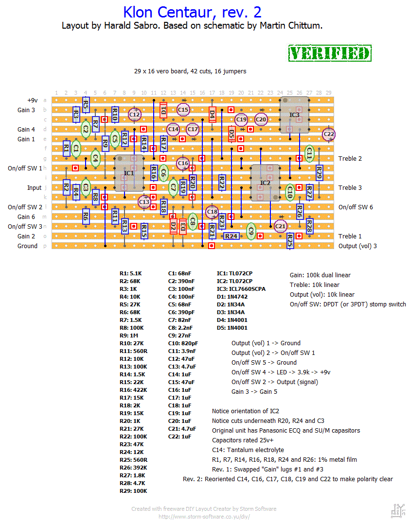
This is the layout:


This is the page:
https://www.sabrotone.com/?p=729

Update
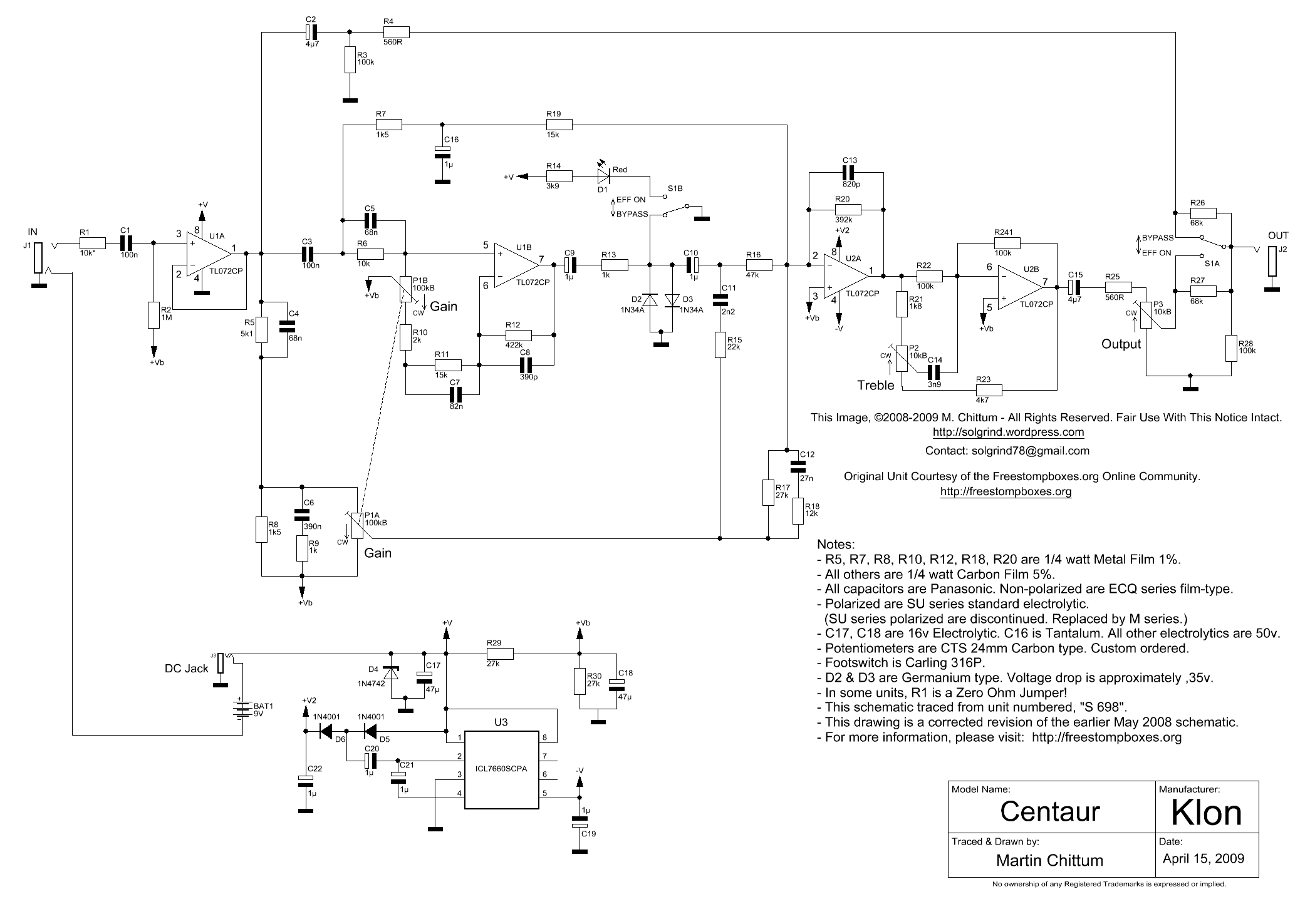
Schematic:


Just one change: C15 from 47uF to 100uF (35v). The other electrolityc caps are 50v. Orientations are ok.
The ICs are the TL072 and 7660S CPAZ.
The clipping diodes are D9E. Every diodes are rightly oriented.
All the pots, the footswitch and the LED is wired.
Dual Gain pot like that:
1 2 3
4 5 6

The Footswitch is a 3PDT and is wired like that:
1 4 X
2 5 X
3 6 X

The circuit sounds, but extremely wrong. Buffered sounds low and crackling at the peak. Engaged the red turn on, the volume is still low, slightly overdriven, the volume pot works but the wide is really small, the Treble pot pretty the same, it's hard to say if it works, as the Gain pot, it crackle when I turn on.

These are the corrected voltages:
      IC1          IC2       IC3
1    +4.43V    +4.6V     +8.84V
2    +4.44V    +4.43V    +4.52V
3    +3.45V    +4.43V    0V
4    0V          -8.44V       -4.13V
5    +4.43V    +4.42V    -8.42V
6    +4.43V    +4.43V    +3.97V
7    +4.41V    +4.26V    +5.29V
8    +8.87V    +15.92V    +8.82V

And these are my voltages:
      IC1          IC2       IC3
1    +1.37V    +4.50V     +9.00V
2    +1.38V    +0.0V    +4.76V
3    +0.93V    +0.0V    0V
4    0V          -8.65V       -4.34V
5    +1.22V    +0.00V    -8.65V
6    +1.16V    +0.00V    +4.63V
7    +8.37V    +4.66V    +4.18V
8    +9.00V    +16.46V    +9.00V

Need some urgent help (and I never say urgent!).

Thanks! ;)
#34
General Questions / Tight Metal huge volume
October 02, 2018, 01:54:39 AM
Hey, guys! :)

I'm building the Tight Metal on a verified veroboard layout I found. I'm testing the circuit, it works fine and sounds really good, but the volume is HUGE. I can't go over 2/10. It's really strange. Every schematic I found suggest a B10k Volume pot, but it's impossible use this normally.
The schematic is this:


The loop effect in my case are jumpered.
I can see the resistor to the ground near the output 47k in another schematic and 33k in Grind Custom FX's schematic.
I know the Tight Metal includes a 18v Charge Pump, too. But the layout I used doesn't have it. I'm gonna include it on a daughter board later.

Need some help, please.

Thanks! ;)
#35
General Questions / Charge Pump: a bit of confusion
September 12, 2018, 01:55:06 AM
Hi, everybody!

I'm going to build the Amptweaker Tight Metal, but the layout I found doesn't have the charge pump, so I have to build a daugherboard.
I bought some ICL7660SCPA, I want to build something based on it.

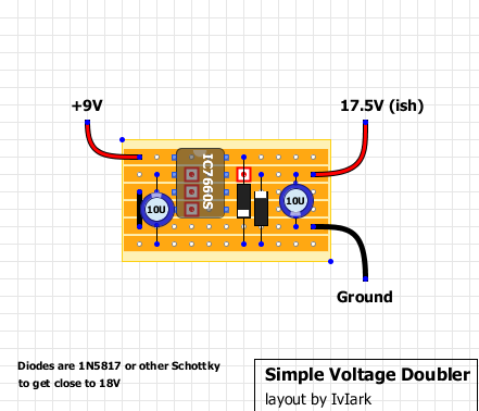
I never used a charge pump, but I always thought the following veroboard layout was simple and good:


Of course, I compared it with some ICL7660S layout. Some of them include some extra parts like a 100uF and/or a 1N400X diode, as filter in the power supply. But the layout of the Tight Metal I have to use already has this accessories parts, and I guess I don't need of them.

And now my doubt about the circuit. I see in the charge pump layout that the pin 5 goes nowhere, so it's isolated. But in some other layout, as some schematic, pin 5 is connected (with the pin 3) to the ground. Why in this layout it isn't so?

Here's the schematic of the Tight Metal by Grind Customs with a charge pump section similar to the veroboard layout, except where pin 5 and pin 3 are connected together, and both go to the ground:


Should I consider to put a jumper to connect the ICL7660S pin 5 to the ground like the schematic?
#36
Hi! With my second Rat building I tried some tricks I read around here and there to get more bass from this pedal.

I tried with my first Rat the Ruetz mod with the pot control (replacing the R6 47R with a 1k Linear pot).
Now I tried to replace the C7 2.2uF with a 10uF. Then I back with the stock caps.
Then I replace the C6 4.7uF with a 10uF, and even the R7 560R with a 220R.
Nothing of that gets more bass, I got just a slightly dull sound, but this is not a Fat/Bass Boost mod I mean.
I guess it's very hard to get more bass from this circuit!

Who knows the real trick to get more bass?

Thanks!
#37
Hey guys.
I built a MXR Phase 45 using not the 2N5952 transistors matched couple, but I tried two any J201 (when we get it easely!) and the effect worked fine immediately.

I would like to build the Phase 90, I don't want to buy a bunch of 2N5952 nor a matched transistors (a quartet) because the cost.
Now the J201 are not available in the shops I used to buy, so I decided to buy some SMD version, MMBFJ201, with the mini PCB.  I read those are exactly the same thing.
Did someone try to use just J201 in the Phase 90?

Thanks!
#38
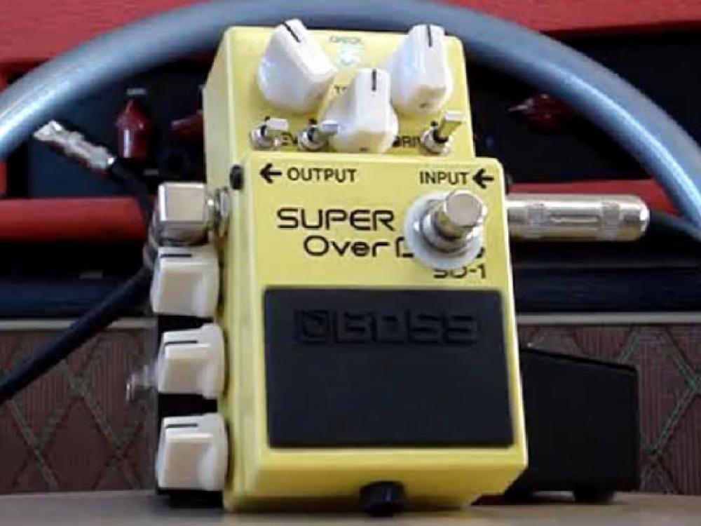
General Questions / What hell happend to this SD-1!
June 15, 2018, 08:25:54 AM
Did you see this?


I'm wondering if that is real or a joke.
#39
Hi, I'm looking some layout of the some DIY True Bypass Looper, one loope effects.
This is the basic schematic:


I found the Keeley one's gutshot:

It' includes a pair of extra resistors. ???
I'd say those resistors are between tip and sleeve of the jacks Send & Return. Pull Down Resistors, just in case we need of them?
Confirm, please?

And then I found some kits that includes a pair of caps (looking at the size I'd say 100nF). I can't imagine the purpose. :(
https://www.dhresource.com/0x0s/f2-albu-g3-M01-3D-B0-rBVaHVWWJNKAcD4PAALdQsq2u7E062.jpg/diy-true-bypass-looper-effect-pedal-guitar.jpg
https://www.dhresource.com/0x0s/f2-albu-g2-M01-A6-C8-rBVaG1WWJQiAd1jqAAK2s6DfiCs398.jpg/diy-true-bypass-looper-effect-pedal-guitar.jpg
https://ae01.alicdn.com/kf/HTB1xhUOHVXXXXbdXXXXq6xXFXXX3/Looper-DIY-Guitar-Pedal-footswitch-true-bypass-Aluminum-Pedals-RED-Box-Foot-Pedal-Switch-handmade-kit.jpg_640x640.jpg

Help, please.

Thank you! ;)
#40
Hello.
Sometime, especially when I have to debug a circuit, I need to know the voltages of some parts as transistor or IC. But when I got the measurements, how I know if them are correct?
Is there a sort of guide, table or instruction?

Thanks for helping!