News:

Forum may be experiencing issues.

Main Menu
Menu

Show posts

This section allows you to view all posts made by this member. Note that you can only see posts made in areas you currently have access to.

Show posts Menu

Messages - LateCentury

#16
General Questions / Re: Aion Refractor Volume
March 05, 2017, 10:59:14 AM
Sorry to hijack your thread, Flock of Bees. Hopefully we'll both get some advice to try.


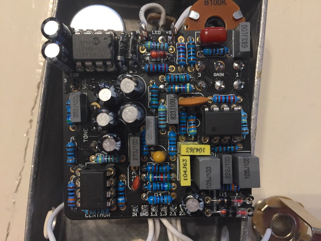
Since I wasn't really happy with the sound the first time around, I made this mods per the documentation:
https://www.dropbox.com/s/4xhwadzx2rxbm8z/aion-refractor-centaur-documentation-v2.pdf?dl=1

R10 = 47R (More gain)
R17 = 10k (Increased volume & treble for the dry signal)
R18 = 4k7 (along with R17 change) Better wet/dry ratio)
R21 = 4k7 (Slight shift in range of Tone knob)
R23 = 1k8 (Slight shift in range of Tone knob)
C13 = 560pf (Slight increase in overall brightness)
#17
I made an etch of this little guy and thought I would try to cram it in a 1590LB.

Bypass works but no signal when clicked on. I don't really know where to begin to troubleshoot. The only sound I can get is a little AM radio when I touch the back of R6-R9  8)

#18
General Questions / Re: Aion Refractor Volume
March 04, 2017, 11:47:44 AM
Quote from: Flock of Bees on January 24, 2017, 07:23:51 PM
Hello everyone,

I just finished an Aion Refractor but the volume is extremely quiet. I have to turn the amp up to 11 to barely hear it. Any advice on where I should be looking for the problem?

I'm having the exact same problem with mine. I used the Silver Pony specs as pointed out on the documentation. Did you try reflowing the volume pot and did it work?
#19
I'm getting 8.33 on pin 3 with the trimmer all the way up.
#20
Here's what I get when I connect the two r10 pads with wire:

1. 9.26
2. 4.59
3. 3.93
4. Varies
5. 0
6. 4.58
7. 4.86
8. 3.90

They seems pretty close. And this is with the trimmer about in the middle. Still, silence when switched on.
#21
Quote from: Scruffie on February 28, 2017, 05:57:53 AM
Try jumpering R10 (just connect a piece of wire directly across it on the back of the board to short it out) and then adjust your bias again and see if you can get output from the BBD (pins 7 & 8).

Do you mean hold a wire on the back connecting the two r10 solder joints together?
#22
Tech Help - Projects Page / Re: Testing rig woes.
February 28, 2017, 05:57:04 AM
Thanks! I'll try this out!
#23
Quote from: Scruffie on February 26, 2017, 01:53:20 PM
Sorry, I should have said before, your bias voltage is too low, have you tried fiddling with the trimmer? And if yes, what's the highest voltage you get on pin 3 of the 3007.

Alright, my volt meter was giving me a little trouble but I fixed it and I'm getting consistent readings.

When I turn the bias all the way down on pin 3 I get 0, then about halfway reads 2.48, all the way up reads 4.55.

Quote from: BrianS on February 26, 2017, 03:36:01 PM
Don't give up.  I know it's frustrating.  I've wanted to sit a couple of my builds out on the interstate to see how much stress the box would take. 

Man. Tell me about it. This is the first of 3 in a row I haven't been able to get to work. Its so maddening I almost want to toss all my unfinishing projects and parts up for sale and wash my hands of this hobby.  :(
#24
Tech Help - Projects Page / Testing rig woes.
February 27, 2017, 12:23:24 PM
I thought I would finally make myself a testing rig after having too many problems with boxing a non-working build first. Yeah, I know.  :-[ 
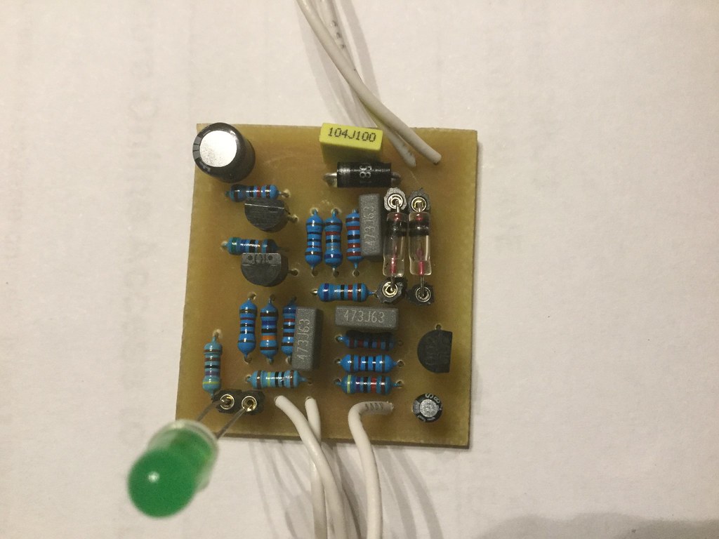
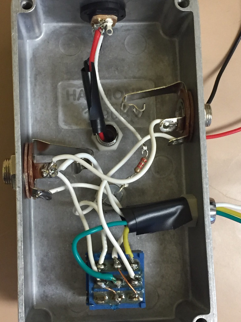
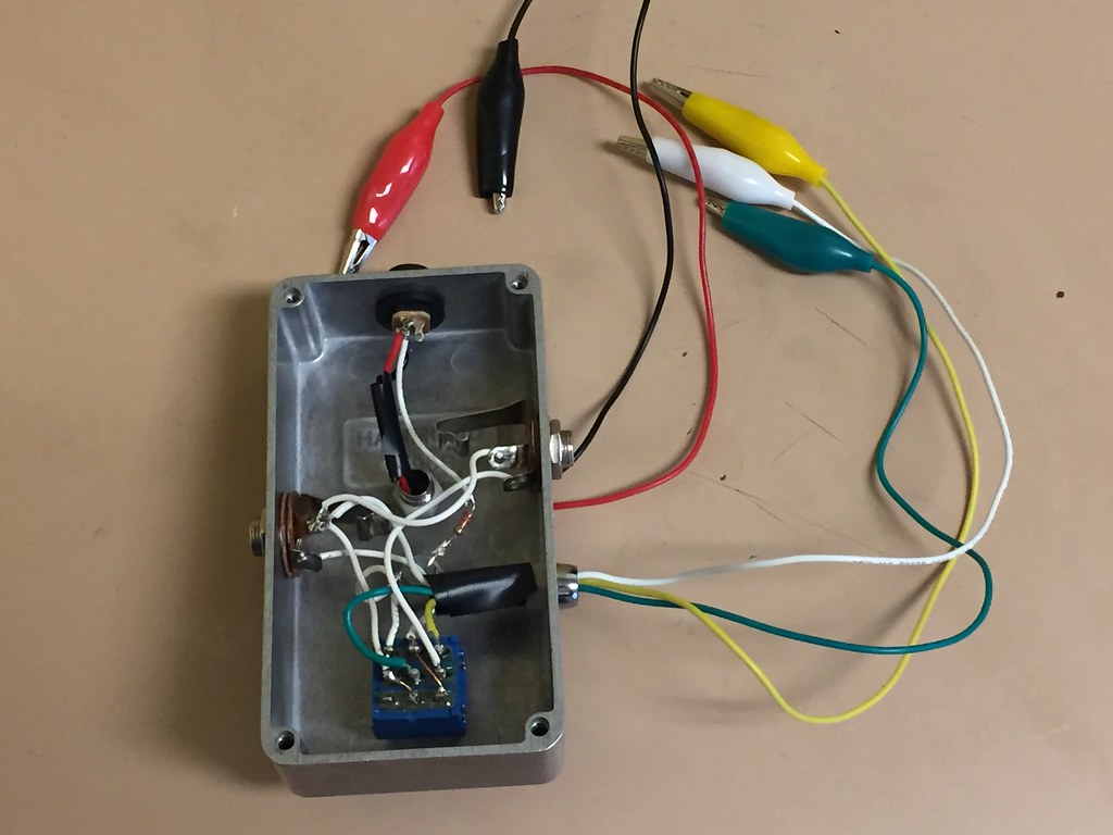
I cannibalized an A/B switch box I made as the case. I thought I had everything correct here but it does not seem to work. It passes the bypass signal fine, but when powering up and switching on a board that should be work, I get nothing. I've traced the wires more times than I can count and it looks like it SHOULD work! I've even tested the switch for continuity. All pins show continuity between middle-top and middle-bottom.

I've got an alligator clip for the board input, board output and ground, then positive and ground for the jack. The boards that I have tested power up and I can touch the L wire from the board to the resistor in the case and It lights up. Am I missing anything?


#25
I reflowed all the joints and got the exact same result.

At what point do I start replacing parts to troubleshoot? If I'm losing audio at R10, do I consider replacing that? Or is it highly unlikely that a resistor is bad?

Thanks a ton for all your help, btw
#26
I took readings with and without the 3007 in. Very different readings this time:

Without:
4.5
.19
1.69
Starts at about 4, then decreases gradually til it hits about .1
4.23
4.23
.21
4.39

With:
4.36
.17
1.92
Starts at about 3, then decreases gradually til it hits about .1
1.12
1.24
4.53

Then, I tried it again and got even different readings:
9.02
4.47
2.16
Starts at about 3, then decreases gradually til it hits about .1
3
3
4.45
.03
#27
Quote from: Scruffie on February 19, 2017, 02:59:49 PM
I don't know if you bought your 3007 through a reputable supplier, but, if you got it off ebay, I would consider removing it from the socket (using ESD precautions) and probing the voltage at pin 3 then to see if the chip its self is shorting it to ground.

I bought the MN3007 from Smallbear last May. Do you mean probing socket 3 with an audio probe or volt meter?
#28
Alright, I got the audio probe working like it should. Makes sense now. I disconnected the fx loop and wired it the normal way. Getting clean bypass. Power LED comes on and rate LFO flashing faster and slower with the rate pot.

When switched on, I get audio at R1-6, then R8-10, C1-4, IC pin 1,2 & 7 and bias pins 2 and 3. Other than that, R26 makes a ticking noise and everything else is just crackling and popping. R10 is a lot more faint of a signal but it's there.
#29
Thanks Brian. The help is much appreciated. For the time being, here is the bottom of the board.


#30
Quote from: BrianS on February 14, 2017, 04:05:09 AM
Ok.  Let's see if you are hooking it up correctly.  Your signal is going to the in jack of the effect (guitar, signal generator, etc...).  The probe phone jack is hooked into your amp and grounded to something.  There is nothing hooked up to the out jack of the effect.  The end of your probe acts as your out jack now, so to say. Not trying to insult your intelligence here so plse dont think that. 

If you want, take the cover off of one of your pedals that's works, hook it up as above, get a signal going through and probe around the board.  That will give you an idea of what you should be hearing. 

That's why I asked if you were getting sound up to C15. If you have no sound at R1 you will have no sound at C15.  So let's determine if you're getting signal to the board when you turn it on.  Thats the beauty of the probe.  If you can follow the signal path off the schematic you can quickly figure out where it stops and that normally will be where your problem is.

So i hooked it up like this and probed nearly the entire board. The only thing I got was humming and louder humming when I touched solder joints. Another wierd thing that was happening was that I had it originally hooked through the effects loop on my amp. I noticed when I had the pedal clicked off, it made a faint flanging signal like if it was turned on. My LEDs are lighting up so there is no mistake whether it is off or on.

At this point I'm tempted to disconnect the optional FX out-inputs and hook it up the regular way to see if that makes any difference.

Also, I have to point out that T1 is not a Bourns 3362P timmer like the others. It is a 10k though. Would that matter at all?