News:

Forum may be experiencing issues.

Main Menu
Menu

Show posts

This section allows you to view all posts made by this member. Note that you can only see posts made in areas you currently have access to.

Show posts Menu

Messages - LateCentury

#31
Brian, thanks for the info. I was totally doing it wrong. I completely misunderstood how it works.

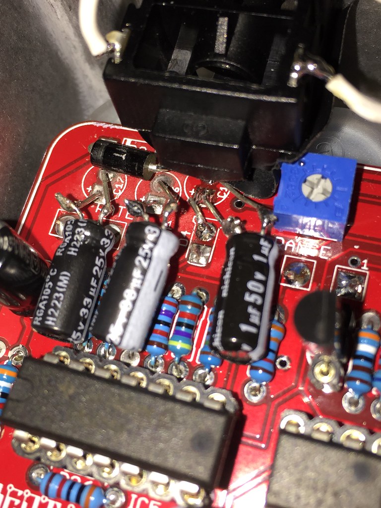
I'm going to go over my solder joints again and melt down the ones that look a little off and see if that does anything first. I think Ive been using solder that has a lower melting point and doesn't always bond when I think it is.
#32
You know what... I don't think I'm doing the audio probe thing correctly. There must be more to it that I'm not getting yet.
#33
Quote from: Matt on February 12, 2017, 10:18:20 AM
are you hearing the guitar at all when probing it just buzzing.

A couple things I'd check is that your output jack isn't grounding out and that your foot switch isn't bad

Actually... I checked again and turned up the amp volume considerably and I CAN faintly hear guitar signal. When I hold my thumb on the output tip so its buzzing and touch the pad on C15, it gets much louder and I can hear the flange effect working. But its still not a full on guitar signal.

So, should I gather from this that its some kind of ground issue?
#34
Quote from: Matt on February 11, 2017, 07:44:33 PM
You are getting audio at c15? Or just buzzing

I plugged the audio probe straight into an amp and poked the points on the board. There's no audio when the pedal is powered up and switched on, so I'm getting only the buzzing from the amp or no buzzing when touching the output at the switch and "R" pad.

Is it correct to assume because I am hearing the amp buzzing at C15 that the audio signal is at least passing all the way through to that component? I don't know how to read the audio path on the drawing.
#35
Quote from: Govmnt_Lacky on February 11, 2017, 08:52:00 PM
Why does it look like D4's cathode (-) is shorted to C18's positive?

Its not touching, kinda looks like it in the photos, but no.
#36
Quote from: Matt on February 11, 2017, 05:21:54 PM
So you don't get any signal no matter how you set the trimmers?  If so, yeah it's audio probe time

Yeah, nothing at all. I made an audio probe this afternoon (this one) and I got a little buzz on basically everything that I touched, except for the "R" lead and the output pad on the footswitch. If I'm reading the documentation correctly, the very next component in the audio path (from the output) is C15...? That made a sound too, so I don't know what I'm doing wrong here.
#37
This build went very smooth up until I decided to box it before I rocked it.  ::) 
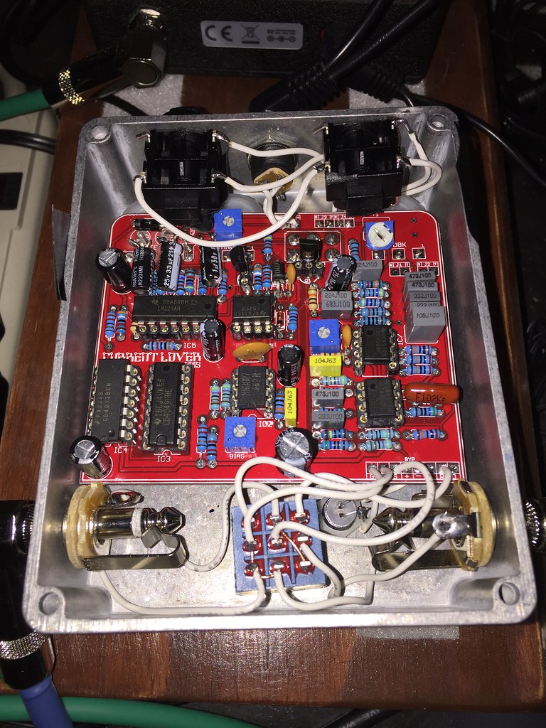
The bypass signal is crystal clear, but when you kick it on it goes silent. I've quadruple checked that every wire is going where it needs to. The optional fx loop is connected the way its supposed to with the switch jacks. The LED lights up, but not the LFO LED. I would think that at least SOME sound would come through.


The close pic of the capacitors is showing a little hack I made to pull them back to make room for the fx loop jacks. I de-soldered them from the board, and re-soldered longer legs to those 3. The diode is not touching the legs and the LFO LED its not either. I don't know if that would matter.

Here are the voltages. The numbers in bold are the ones that appear massively different from the documentation.

Voltage at power jack: 9.31

IC1 4558
1. 4.66
2. 4.66
3. 2.32
4. 0
5. 4.53
6. 4.53
7. 4.39
8. 9.63

IC 2 MN3007
1. 9.03
2. 4.48
3. 0
4. 0
5. 0
6. 4.48
7. 2.56
8. 2.57

IC CD409
1. 9.02
2. 4.48
3. 4.47
4. 4.47
5. 4.49
6. 4.46
7. 4.49
8. 0
9. 4.47
10. 4.48
11. 4.47
12. 4.48
13. 0
14. 4.47
15. 4.48
16. 0

IC4 CD4013
1. 4.48
2. 4.48
3. 7.33
4. 0
5. 4.49
6. 0
7. 0
8. 0
9. 0
10. 0
11. 0
12. 9.03
13. 0
14. 9.02

IC LM324
1. .5~7.5
2. 4.02
3. 2~5
4. 9.01
5. 0
6. 0
7. 7.74
8. 1.03
9. 1.03
10. 0
11. 4.01
12. ~
13. 4.09
14. 3.5~4.5

IC6 LM311
1. 0
2. 4.96
3. 3.42
4. 0
5. 9.03
6. 9.03
7. 7.32
8. 9.03

IC7 4558
1. 4.51
2. 4.51
3. 4.51
4. 0
5. 4.01
6. 4.52
7. 4.52
8. 9.01

Thanks in advance! This is so frustrating!
#38
Tech Help - Projects Page / Re: Glam - Volume Drop
January 26, 2017, 09:09:18 AM
I'm having this same problem with the Wigl. I'm not very adept at reading schematics... would increasing R9 on the Wigl have the same effect in a volume increase? Or would it be a different resistor?
#39
Build Reports / Re: 1590 Gs
January 22, 2017, 07:54:08 PM
Wow those look good! I'm curious to see this insides, I've done two 1590g's and haven't been able to close up either without spacers. I love the finished size but it is maddening!
#40
Build Reports / Re: Aion Refractor build: Hippocampus
January 22, 2017, 07:50:34 PM
Quote from: darrenw6000 on January 22, 2017, 02:58:44 PM
Cool this is a project that I'm going to be doing soon, have you ever built madbean's  kingslayer, if so how do they compare.

I have not built the kingslayer but now I kinda want to. I actually didn't like the sound at first but am now warming up to it. From the Aion docs, they list the original having Germanium diodes. I used 1n914s. I'm curious to know if there is much of an audible difference. Using this pedal with my current gear has me eq-ing my who setup again. It was difficult to get it to sound right at first without a massive tone difference when clicked on.
#41
Build Reports / Re: Aion Refractor build: Hippocampus
January 22, 2017, 02:46:08 PM
Quote from: jubal81 on January 21, 2017, 11:27:30 PM
Yowser, looks great! Insides squeaky, too.

Mind going over your process for  transferring laser prints with polyurethane?

Sure!

First, print out your design BACKWARDS on a laser printer. I have a color laser printer at work I use. I print on standard printer paper, nothing special. You need to keep in mind that the ink transfer is translucent. So, apply your color theory knowledge here. Example: If you have a yellow enclosure, and you have blue in your design, the transfer will make the blue areas appear green. Typically, I have been doing lighter colored enclosures so my designs can be predictable. Black in your design will always appear black, no matter what color your enclosure.

Once you have your box ready, apply a coat of polyurethane evenly across the surface. I just use a small foam craft brush. Then, carefully lay your design face down. Go slow so you can line it up carefully. You can't reposition once its down.

Starting from the center, press down and outward on the paper, pressing the design as flat as you can to the enclosure. I then use the handle of the brush to roll across the paper evenly. You'll probably goosh some poly out of the sides, but that's ok.

I let it dry for 24 hours to make sure it's cured nicely. Once it's dry enough, run it under a warm trickle of water. The paper will begin to soak and slough off. Very, VERY carefully, rub the paper off with your fingertips. It should ball up and roll off in tiny strips. Keep going until your design comes through and it looks like all the paper fibers are gone. If you aren't sure, dry it off and any remaining paper will be visible and feel a little rough.

This process of transferring the paper to your enclosure will leave it with a dull-ish finish, FYI. So, the next thing you'll do is apply another thin, even coat on the surface. I usually try to watch for bubbles and pop them with the tip of the brush to ensure the smoothest surface possible. You can cover the whole enclosure with poly, but you'll probably have to do it in stages. It's quite runny, so any surface you cover will need to dry face up.

I usually only do two coats of poly on the surface. Polyurethane dries with a very slight yellow tint, so many coats of this and a white enclosure will start to appear yellow. Two seems to look ok and give you a glassy finish.
#42
Build Reports / Re: Aion Refractor build: Hippocampus
January 21, 2017, 10:36:24 PM
Quote from: bluescage on January 17, 2017, 01:57:37 AM
Nice guts! Seems that one picture isn't there anymore?!
Gah! Picture is back up.
#43
Build Reports / Aion Refractor build: Hippocampus
January 16, 2017, 07:22:48 PM
This was probably my best build yet. I think I've more or less found the best method of transferring laser prints with polyurethane. More than anything I'm glad the switch, jacks and pcb aren't fighting for space after having dealt with 1590a's and G's. I think I might have to stick with B's. Oh, and it sounds great! No trouble shooting, worked the first time.


#44
Build Reports / Re: Moodring build: Adrift
November 04, 2016, 12:17:25 PM
Quote from: Leevibe on November 02, 2016, 05:58:06 AM
Really beautiful! I've contemplated bottom mounted jacks but never tried them. How are you liking that configuration?

I use a variety of sizes and configurations of pedals on my board, so I have all kinds of varying length cables. I usually need to move things all around when I add a new pedal. It matches up well with pedals that have top mounted jacks!
#45
Build Reports / Re: Moodring build: Adrift
November 04, 2016, 12:12:43 PM
Quote from: jonnygreentrees on November 02, 2016, 03:23:55 AM
that looks awesome, how did you do the artwork? Sticky label?

I made a color laser printout and transferred it to the enclosure with this technique using acrylic polyurethane: https://www.youtube.com/watch?v=_lTh4JJyZtA