News:

Forum may be experiencing issues.

Main Menu
Menu

Show posts

This section allows you to view all posts made by this member. Note that you can only see posts made in areas you currently have access to.

Show posts Menu

Topics - Aleph Null

#21
This is my take on the Runoffgroove "Grace" overdrive.


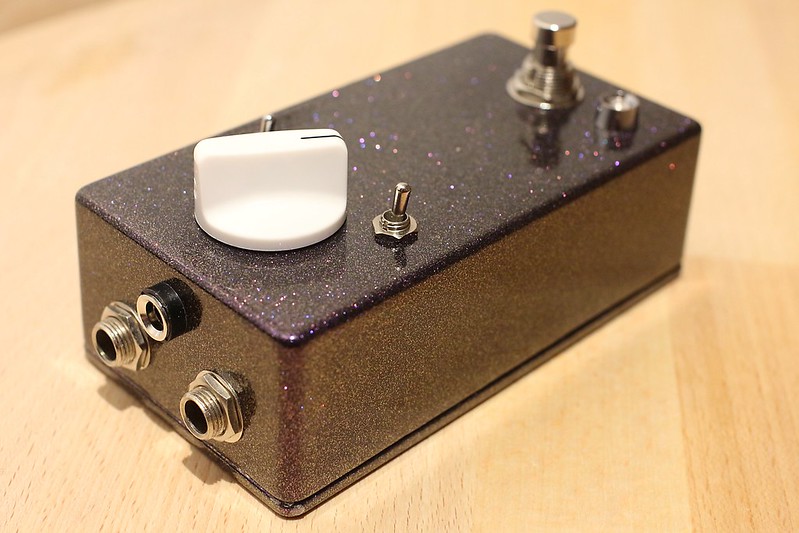
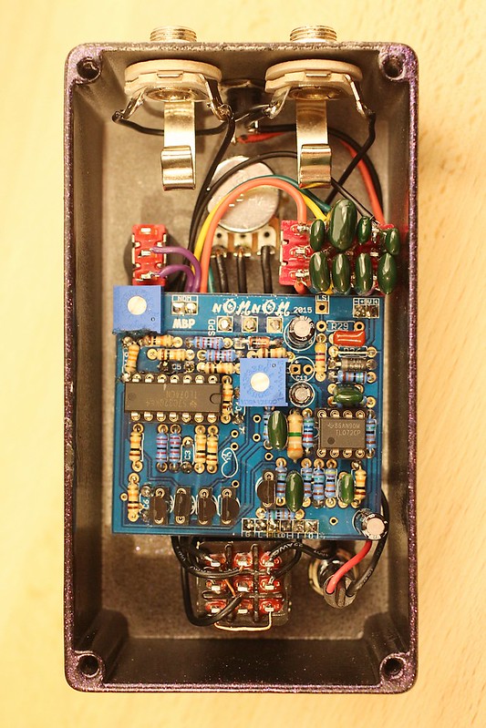
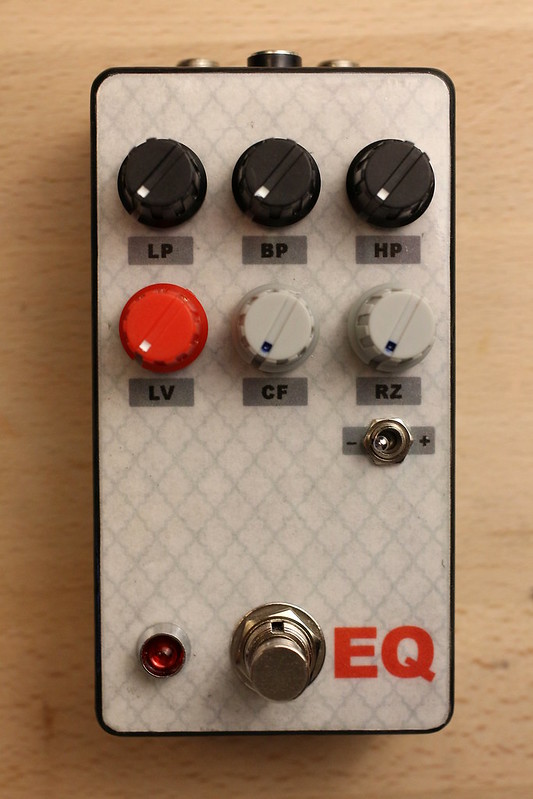
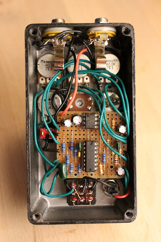
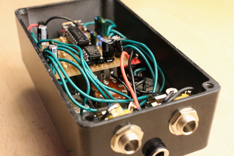
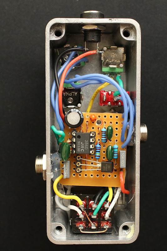
The JFET input buffer of the original is replaced here with a BJT buffer for an input impedance of around 1M ohm (depending on the transistors gain). Bias voltage is taken from pin 7 of the LM386 which saves a couple resistors and a little bit of space. A tilt EQ sits at the end. Unlike a BMP, this offers a mid bump. The switch bypasses the tonestack.


This has the characteristic crackly decay of every other LM386 overdrive I've heard. I wouldn't want to use this into a clean amp, but it does sound very good pushing a dirty amp or another overdrive. You get that percussive attack and the mid boost in the tone control keeps everything tight.


#22
Build Reports / Kaleidiscope
July 21, 2021, 05:06:48 PM
This is a basically stock Pedal PCB Minnow, I reduced R13 from 100k to 91k which reduces the minimum resonance a little. I found this to be useful in the sample/hold mode.


This circuit was quite noisy at first, but only in bypass. I shielded the input and output cables and this helped a little. Eventually, I traced the noise to IC2, the LFO opamp. It was screaming like Satan's own 56k modem and the output jack was picking it up. I replaced the TL072 with a JRC 2068D. The scream became a loud hiss. I covered the opamp and socket with masking tape, then shielded that with HVAC tape, which is grounded to the enclosure. That got rid of the noise.


This is a fun circuit, but definitely plan on having to debug it to get it sounding right.
#23
Build Reports / Trident Fuzz
March 01, 2021, 05:03:42 PM
This circuit was born out of experiments with Tim Escobedo's Triple Fuzz. The heart of that circuit is the non-selective octave tripler (the transistor array shown below). The octave tripler remains mostly intact, but everything around it has changed.


The first opamp stage sets the gain. The 100pF capacitor shaves off just enough high end to keep the hiss down at high gain settings. The transistors form the non-selective octave tripler. This stage creates false harmonics, but doesn't actually distort the signal. Orange diodes to ground do actually distort the signal. The second opamp stage is an active high shelf filter centered at 723Hz with 13dB boost and cut.


With the gain set below 9 o'clock a subtle sub octave is present and the signal is mostly clean. Between 9 and noon, the false harmonics become increasingly present and the sub octave disappears, but the clean signal is still audible. Above noon, the LEDs start to clip and the signal becomes increasingly saturated. There's a very percussive, klangy attack throughout. This is the only fuzz that I've encountered that sounds good at low fuzz settings.


Here's my vero layout in case any one else wants to play with this. It's probably not the most efficient layout, but I had to constrain the width to get it to fit in a 1590A.
#24
Build Reports / Minimalist Tube Screamer
January 06, 2021, 08:25:52 PM
I tried to reduce the venerable circuit down to it's essence: a mid-range focused overdrive. The graphics are also minimalist.  :P


I've been really enjoying single knob gain circuits because they force me to pay more attention to my playing and to work the knobs on the guitar. That said, this circuit has a little more gain and a little more treble than I'd normally use in a Tube Screamer because those can be tamed with the guitar volume and tone respectively.


This design is not as mid-focused as an original TS. The bass is rolled off below 312Hz and the treble is rolled off above 3.1kHz. Additional filtering after clipping rolls the highs off above 4.8kHz, just enough to tame some harshness.I used a linear taper pot so that the "boost" portion takes up most of the sweep. There is only a modest amount of gain on tap compared to a lot of boosts, but it's still enough to push an amp. It does what a TS does: tightens things up and adds some grit.


Lastly, here's the vero layout in case anyone else wants to play around with this.


#25
Build Reports / Push Me Pull You
January 05, 2021, 07:23:01 PM
This is a vero realization of Tim Escobedo's Push Me Pull You. The nice thing about this circuit over other analog octave up designs is that it doesn't require closely matched diodes or a transformer—just two transistors with similar gain characteristics. This circuit responds similarly to other analog octave circuits (best on the neck pickup around the 12th fret), but with more flexibility than something like a green ringer. Cowboy chords at low gain settings creating really interesting intermodulation distortion which you can't get anywhere else. Even at minimum gain, there is still a modest boost on tap (maybe 6dB). Higher gain settings offer plenty of gain to push an amp or another pedal.


The graphics are water slide under clear coat.


Potentiometer lugs are grounded through the chassis. Laying down the electrolytic capacitors allows for enough clearance even in a 1590A enclusure.
#26
General Questions / Fuzz Face Q1 Gain
March 30, 2020, 11:12:21 PM
The sweet spot for transistor gain is pretty well established for the Fuzz Face circuit and part of the problem with silicon versions of the circuit is that it's difficult to find transistors in that 80-100 or so hfe range.

Shouldn't it be possible to adjust the gain of Q1 with a potentiometer in series with the emitter and ground? Every version of this circuit I've seen just ties the Q1 emitter straight to ground. It seems like being able to adjust the gain with a pot would make it much easier to dial in a good sound without need to test a whole bin of transistors.

Is there something in the circuit that wouldn't allow for this? Is there some negative side effect I'm not thinking of? I'd love to hear everyone's thoughts.
#27
Build Reports / The Hermit
March 02, 2020, 04:10:05 PM
This is Mad Bean's Mood Ring with a short Belton Brick.


Old tarot art makes great pedal art. I could see making a whole tarot themed pedal board. I went for purple because I don't have any purple pedals yet.


I found that even the lowest gain settings resulted in runaway feedback with the Dwell control turned up. I jumpered R29 to reduce the gain in the feedback loop. Now I can adjust the gain trimpot so that infinite reverb occurs at around 8 and self oscilation at 9 or 10. Increasing R30 would probably also work, but I had already populated the board and R29 was easier to reach. It may be that the short brick is more prone to feedback than the long brick that this circuit was designed for.


Between the Pre-Delay and the Dwell control there's a wide range of decay time available. The BMP tonestack, with it's scooped midrange makes it easy to dial in lots of reverb without having it overtake the dry signal.
#28
Build Reports / Psuedacris (Pork Barrel 2019)
November 14, 2019, 03:53:30 PM
I built this with an MN3207 that I had left over from a flanger build. I originally ran the wires form the jacks to the switch directly under the board. This resulted in prominent ticking. I rerouted the wires along the left wall of the enclosure and the ticking went away completely


I drew the frog by hand in pencil, then scanned it and touched it up in Gimp. The lettering is my engineer's print that I scanned and cleaned up as well.


If you look closely, you can see where I burned through the powder coat while polishing the clear coat. I've done this on enough builds that I'll be experimenting with refinements to my finishing process. I hate paying extra for a powder-coated enclosure and then distressing it.


I may increase the speed of the LFO some day, but I actually think slower rates suite this waveform (triangle?) better than they would a traditional vibrato. Vibrato mode yields more of a "warped vinyl" sound than a traditional vibrato sound. On the whole, I'd say the "Mix" control does make the effect more versatile; you can use high rate and depth and dial back the mix to avoid the sea sick sounds.
#29
Build Reports / Meat Ritual
October 01, 2019, 08:39:03 PM
This fuzz was made on a whim. It was inspired by the Meathead, Ritual, Snack Shack, and the like. I used what I had on hand, so I took some liberties with the values. Only the enclosure, foot switch, and power jack were purchased to complete the build.


The bypass indicator isn't an LED, but actually a wheat bulb. It's brighter than a dying star. I used an actual guitar potentiometer with a 3/8" (10mm?) shaft. This made it easy to get the position indicator in place.


I'm a glutton for punishment: I used sockets for the transistors and standing electrolytic capacitors.


This schematic reflects the values I had on hand at the time. I tested a few different transistor pairs and settled on two 2N3904: medium/low gain for Q1 and high gain for Q2. You could probably get good results with a 2N5088 in Q2, but it squeals in the Q1 position.


It cleans up with the guitar volume knob nicely and there's plenty of output. The decay tends to sputter out, but this could probably be minimized by upping the 10uF electrolytic to something bigger.
#30
Build Reports / Rage Face — Aion Flare
September 05, 2019, 04:07:09 AM
Given that this is a direct descendant of the Fuzz Face circuit, and an iteration on a pedal that has a reputation for being user unfriendly, the name seemed appropriate.


Giant 10mm red bypass LED sits between the fuzz and volume knobs.

R7 was reduced form 150k to 100k to improve the range of the "soft" control, which I've labelled "gain". The name change means the "gain" knob works backwards, but that's hardly the most confusing part of this effect. C6 is 22nF instead of 18nF because that's the closest value I had on hand. This also increases the range of the control a bit, which helps to tame the more "velcro" settings.


Transistors are from Small Bear:


    Q1: 2N3904
    Q2: 2SB175 (gain 50–80)
    Q3: RCA 2N652 (gain 110–150)

I tested 2N3906s in Q2 and Q3. I don't recommend them. The "fuzz" control started at "too much" and went up from there. The "soft" control was useless. The transistors I settled on are in the commonly accepted sweet spot for gain in Fuzz Faces and with them all the controls are more useful.


This was a fun build. I'd say the extra three knobs increase the versatility (and unwieldiness) of the circuit.
#31
Build Reports / Trem de Lune
August 28, 2019, 03:14:38 PM
This is an almost stock Aion Electronics "Luna".


I tried a few different designs before settling on this graphic. I think the Victorian man-in-the-moon design communicates well from under foot. I used a blue diffused LED for the bypass indicator and a red waterclear for rate.


IC2 is a TL062 instead of the recommended TL022. Having seen many variants of this circuit, it seems any low-power opamp will work without producing audible clock noise. I went with the vactrol for this build instead of rolling my own. I've had good luck with the LDRs from Tayda before, but the square wave setting does sound a little more square to me with the vactrol.


The Aion layout makes it easy to keep wiring tidy.
#32
General Questions / Pedal Fixation Methods
July 10, 2019, 11:04:28 PM
I know that velcro is the most common approach to fixing pedals to a board, but surely not everyone here is using that method. If you're not using velcro, what are you using and why? If you tried something and moved back to velcro what did you try and why did you go back?
#33
Build Reports / The Clampressor
May 09, 2019, 04:06:19 AM
This is a stock Mad Bean 4:1 compressor, except I used an LED/LDR pair in place of the Vactrol. They're just whatever Tayda carries (don't worry; I had the good sense to buy my ICs elsewhere!  ;D ).


I'm a die-hard top-mount-jacks guy. A 125B with TMJs is just the most space-efficient layout for pedal boards.


I widened the pot spacing to make better use of the 125B. The graphic is a water slide decal suspended in Mod Podge with an acrylic clear coat.


I wasn't sure how well the LED/LDR pair would work in place of the vactrol, so I replaced R12 with a 22k resistor in series with a 50k pot. This allows enough leeway to adjust the range of compression available. C5 was installed on its side to provide enough clearance for the input jack.

#34
Build Reports / Nom Nom with Mods
March 04, 2019, 04:06:46 PM
This is a standard Nom Nom with a few small changes. I couldn't source a 25k trim pot for the feedback loop, so I upped R19 from 22k to 33k and used a 10k trim pot. I was still able to dial it in without self oscilation. The second switch changes C3–C6 from the stock values to univibe values.


It's very difficult to capture the enclosure color in a photograph. It's Cherry Violet Sparkle from Mammoth and it looks awesome in person. I liked the finish so much, I opted not to cover it with labels. It's pretty easy to remember what control does what on this build anyway.


The univibe switch is definitely a worthwhile mod. It's not going to satisfy a diehard univibe fancier, but it is reminiscent of one with the intensity turned down. The univibe setting seems to be able to handle much lower resistances in the feedback loop than the phase 90 mode. Anyone looking to build with these values only might consider jumping R19 and using a 50k trim pot. I'd probably also jumper the Nom switch.


In order to accommodate the 4PDT switch needed for the univibe setting, I created custom pot standoffs using 18AWG solid core wire.
#35
General Questions / 4:1 Photoresistor Options
November 23, 2018, 03:57:20 PM
The BOM calls for a VTL5C3, but I have Tayda photoresistors on hand. Light resistance is 5k which seems to be about right. If I use them with a 5mm red LED in this circuit, will I regret it?

I'd love to hear from anyone who has done this. Did you have to change any resistor values to get good results?
#36
Mods / Nom Nom Capacitor Values
October 29, 2018, 04:25:13 PM
I see Brian has suggested changing the cap values in the phase section of the Nom Nom for a vibe-ish sound. Has anyone played with the values here? What values did you settle on?

I'm considering two switches: one to change the C3 and C4, and another to change C5 and C6. Would changing only two stages be a significant enough change?
#37
Build Reports / Super Tone Control
October 16, 2018, 03:16:12 AM
Anderton's Super Tone Control on vero (layout form Tagboard Effects). This circuit behaves more like something you'd find in a synth than a guitar amp or channel strip. It can produce a wide range of sounds, but the controls are highly interactive, which can make it a little fiddly.


Originally, I had wanted to do pictographic labels for the controls, but there wasn't enough space with all the knobs. Once I had decided to name it "EQ", I settled on two-letter labels. From left to right, top to bottom they are: Low Pass, Band Pass, High Pass, Level, Center Frequency, Resonance, (and a resonance low/high toggle).


Finish is printer paper and Mod Podge under an acrylic clear coat.

18v charge pump built in. The original schematic calls for a dual-gang A10k for CF. I could only source an A100k. I upped the 33r resistors to 330r and it works as it should. The A10k LV pot keeps the output impedance low. RZ is wired backwards because it felt more intuitive.


I used solid 18awg wire to the resonance switch to act as stand offs. This floats the board over the LV and CF pots.
#38
How Do I? Beginner's Paradise. / CD4049UB. Y Tho?
August 29, 2018, 03:53:53 PM
The snark doodle, red llama, and all such similar call for the CD4049UB, but use only two of the gain stages. It's always seemed strange to me that the other four are just wasted. Is there something special about the Hex CMOS buffer? Couldn't you get similar results by slamming the output of one TL072 stage into the input of another? Please school me.
#39
Build Reports / Tesseract — Distorted Reverb
March 29, 2018, 04:03:39 PM
I managed to cram it into a 125BB with top mount jacks! The Chaos Control has been moved to the outside of the box. I took some liberties with the control names.


I had to get a little creative with jack placement. The extra height of the 125BB is definitely required for top mount jacks.


The finish is ink jet on printer paper. I used acrylic as a fixative, then Mod Podge to adhere the print. More acrylic went on after that for the clear coat. The enclosure was quite rough, so I had to do some serious buffing just to get the "distressed" look you see on the sides here.


I wanted a little more chaos, so I substituted a B25k for the recommended B100K pot. It's still more subtle than I had anticipated in some settings. I may also find a way to bypass the resistor in the feedback loop (R27) for even faster swell speeds. I built this initially with a short Belton brick, thinking it would be more versatile. That may be, but the short brick would not self oscillate at all in this circuit.


Some of the larger caps are bent forward to accommodate the jacks. I was having flashbacks to failed 1590A builds as I boxed this! Still, I'm glad I went with a smaller enclosure.

Thanks, DiabloChris666, for making this PCB available.
#40
General Questions / Pork Barrel Blend
February 23, 2018, 11:09:04 PM
I'm looking to add a blend control to the Pork Barrel. It looks like the wet and dry signals are mixed before hitting IC1_B. Could I omit R9 and R26 and use a b100K pot in their place?


RedLug 1
GreenLug 2
BlueLug 3

Would this be enough resistance to go 100% dry to 100% wet?