News:

Forum may be experiencing issues.

Main Menu
Menu

Show posts

This section allows you to view all posts made by this member. Note that you can only see posts made in areas you currently have access to.

Show posts Menu

Topics - mjg

#41
Build Reports / Slow Gear clone
May 02, 2017, 11:29:27 PM
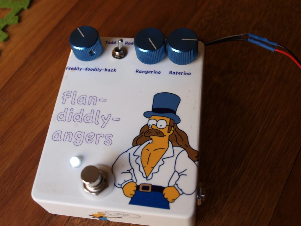
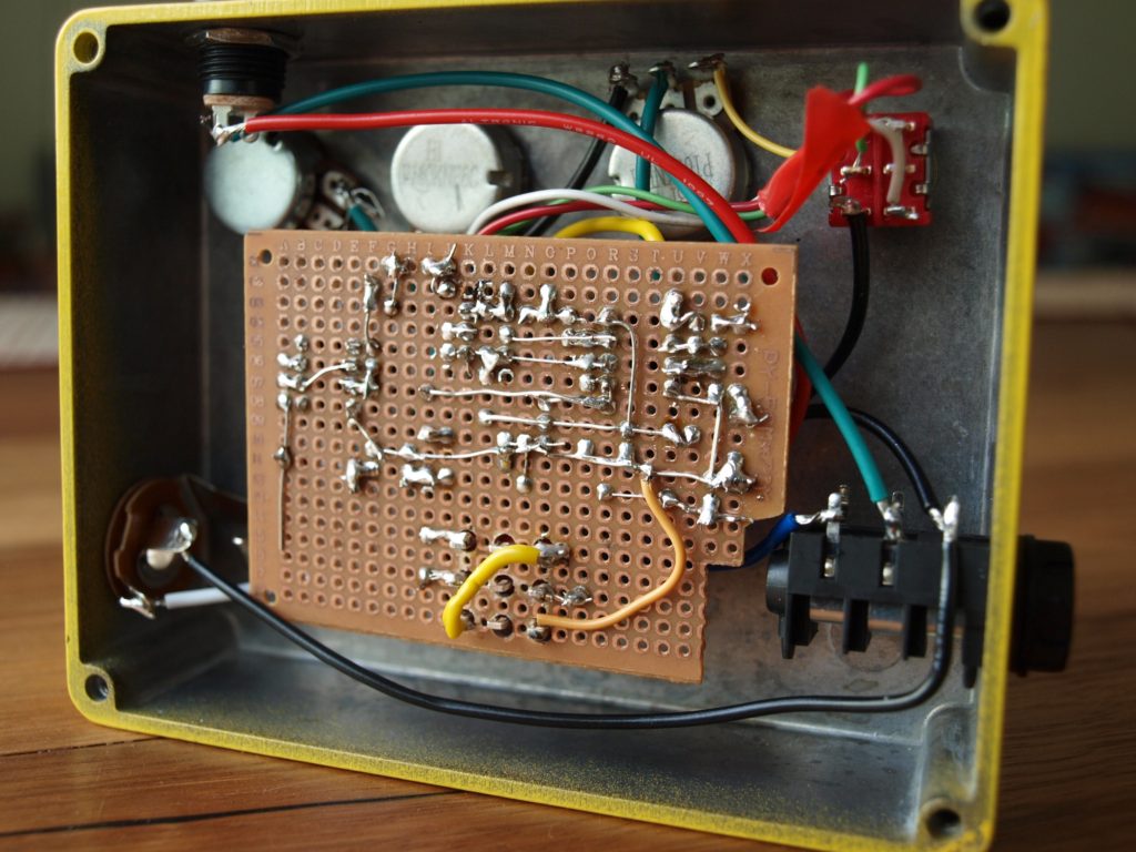
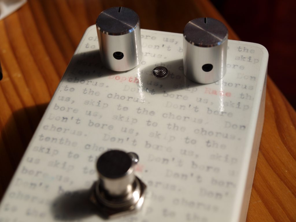
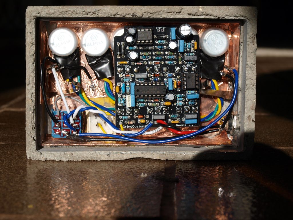
This is from a PCB that I got in the holiday PIF - thanks to Tremster!   

It's a fun pedal to play with.  Works well with the guitar and bass. 

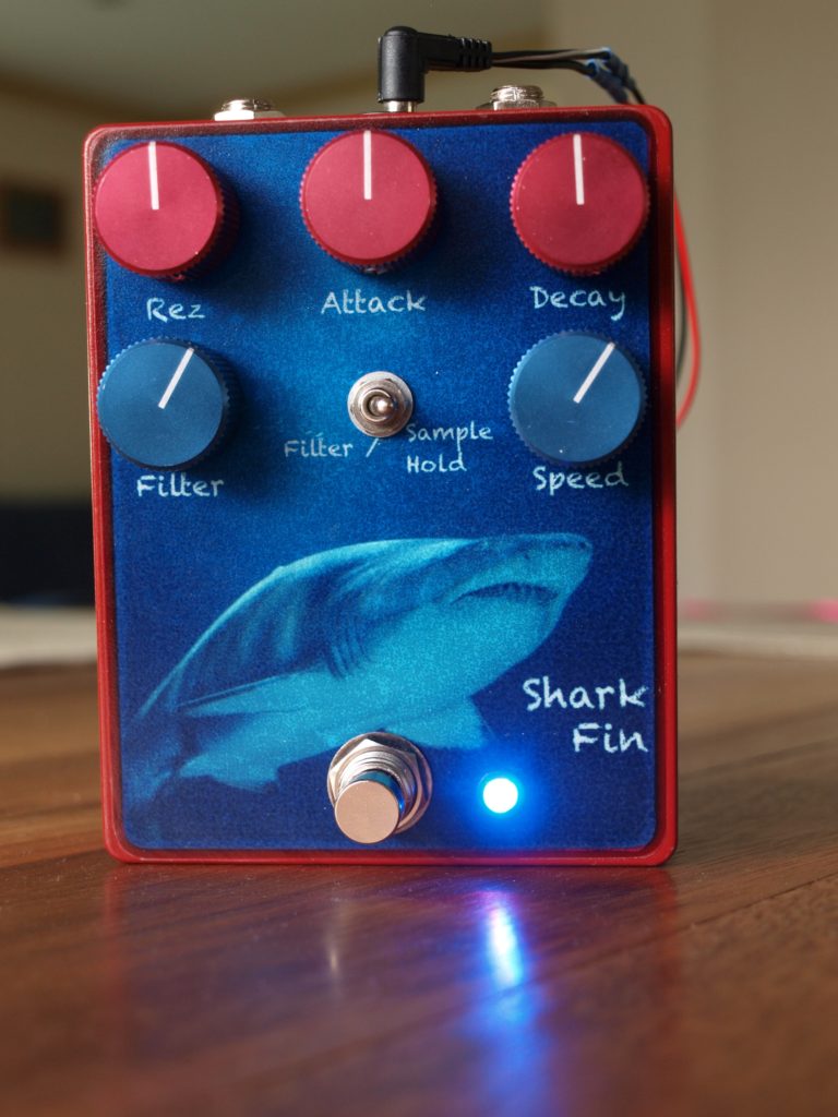
I've used a 25kB pot and 1u capacitor for the attack control.  There seems to be a few different BOMs for this pedal floating around, so I trialled a 100k pot, and a 0.47u cap, didn't make much difference on my setup, so went with the first values. 

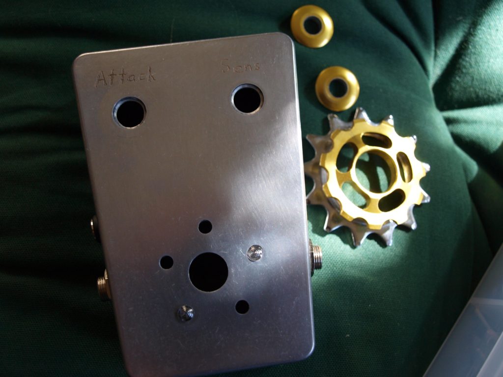
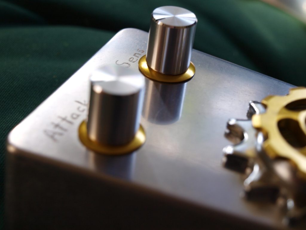
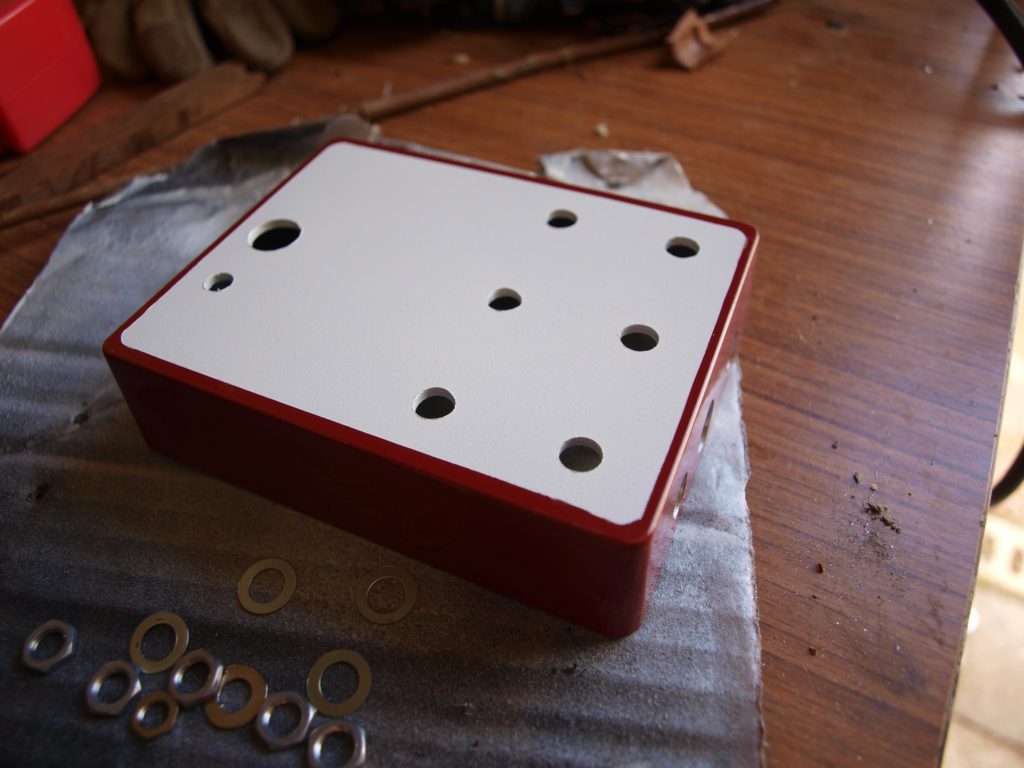
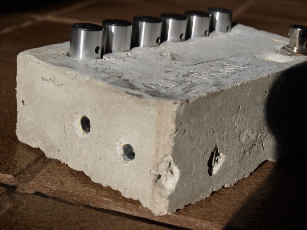
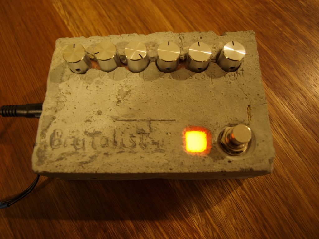
Enclosure is the trapezoid Hammond.  Decorations are bike cogs, which I've stuck together and onto the top with PU glue.  That stuff is awesome.  I was skeptical that it would work on metal, but no issues.  Those cogs aren't coming off. 

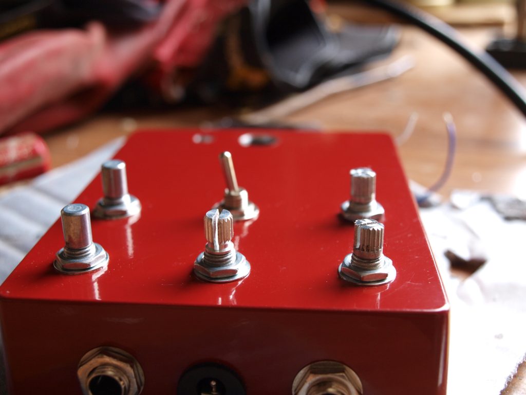
I had to cut down the pot shafts, and also cut the nuts, so that the knobs would fit on flush with the bike bits. 

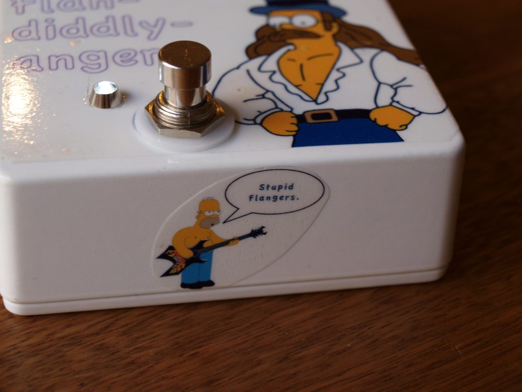
Five LEDs in a ring around the switch, under the cogs, so the whole centre bit glows.  Initially had 5 yellow LEDs in there, but made the mistake of assuming I wouldn't need a CLR for that.  Pop go the LEDs.  Only had white ones to replace them with. 

Writing has been done with a rotary tool with a diamond bit.   It's a bit messy ... filled it in with gold nail polish, then sanded off. 

The top of the enclosure has been sanded with 2000 grit wet paper, then polish.  It came up super shiny, which lasted about 3 minutes before it had finger prints all over it.  :)


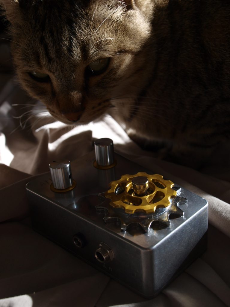
Oh, and this is what happens when you try to find a nice sunny spot to take photos of the finish.  The cat comes and claims the sun.   ::)
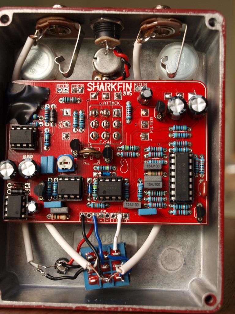
#42
Open Discussion / NSD
April 25, 2017, 02:01:29 AM
It's New, but really old, Soldering iron Day.

I was visiting my grandmother on the weekend - she's 86.  At the moment she is trying to clean up her garage, as she "doesn't want to be a burden when she's not around any more".  Her words. (For reference, she gave up chopping her own wood with an ax last year).

She ended up giving me a soldering iron that belonged to my granddad.  He died about 25 years back, so the iron is at least that old. Also a tin of flux, which had the price in shillings and pence, which would be pre Australia going to metric.  Probably purchased in the 1960s? Earlier?

Anyway, this iron is a monster. 100 watts. The tip is about the size of my finger. Not sure what I'll be able to use it for, for fear of setting things on fire!  The solder was a bar of metal the thickness of my finger.  Enough to drown ICs in a single pass.

There was also a cupboard full of plans for building your own submarine, so maybe that's what a massive soldering iron is good for.  ;)

I'll post some pics once I get them off the camera.
#43
Build Reports / Glam
April 11, 2017, 09:34:17 AM
Finished off a Madbean 'Glam' chorus today. 

This one is the first pedal that my kid has done all the soldering on.  He's helped out with resistors and caps in the past, but this one he did everything on the board, and the jacks.  It fired up first time, which was a relief! 

He turned 10 years old last week... where the hell did that time go? 

The 3PDT board is connected using PCB header sockets.  Worked really well, as long as you don't mind the stomp switch being right up against the bottom of the main board.  Makes for an easy assembly as you can just push the switch daughter board in to place.   

Enclosure was done with a vintage typewriter, onto sticky back plastic, with some clear gloss sprayed over the top.  Any typos are the genuine article... no delete key on that thing.  No copy/paste either.   :P

Only regret is that I didn't quite get the typing lined up properly, I think if the word "Glam" was just below the LED rather than half underneath it, that would be nicer.  Oh well. 

The quote is actually a Roxette album name.  Shameful I know.  But it popped into my head and I thought it worked well... only realised later where I must have got it from. 

The effect sounds good - it does give quite a volume boost, as the build doc says it might.  I've not experimented with R9 to see if I can fix that, but I don't mind the boost.  The PT2399 that I used was a cheap eBay purchase... it is a bit noisy and has all sorts of funky junk going on quietly in the background.  I will probably swap in a few others to see if I can get one that's a bit nicer. 

Also works quite well with the bass guitar.   Some nice ringing sort of tones with the knobs up full. 


#44
Build Reports / Sharkfin
April 01, 2017, 09:31:53 AM
Finally closed up a Sharkfin build today.  This one has been kicking my butt a bit, trying to figure out why it was making an ugly ticking noise in bypass mode.  Changing to shielded wires for the jacks, and running them direct to the 3PDT seems to have helped, and I also had to run the ground wire down from the rate LED to reduce the ticking noise.  All very strange, and the guts now don't look as neat, but it sounds OK. 

This is one of those weird sounding pedals that I like to build, then think "but when would I ever actually use this?".  The 'sample hold' sounds awesome... but I can't think of a song that it works with. 

The filter section also sounds really good.  You can get all sorts of sounds out of it depending on the settings.  Also sounds good with bass.  Very funky.  But I was rolling on the floor when we discovered the magical setting where bass guitar started to sound like really bad bathroom issues.  Hilarious. 

Enclosure is a Hammond red, which I've sprayed white on the top.  Then an inkjet sticky label.  The photo is one I took... they are beautiful looking creatures (when there is 5cm of plastic between you and them). 

I couldn't handle that some of the pots I used were different shaft lengths - so took to them with an angle grinder to even them up.  Tayda knobs on top. 

I've used a bi-colour LED - blue for effect on, and red flashes for the rate. 


#45
I've recently finished a Sharkfin (2015) build, and it works great, except for a niggling little issue or two.  I can work around them, but I'm curious as to the 'why' of what is going wrong. 

I wired it up with the top mounted connections, and a 3PDT board at the bottom. 

Problem 1) Works fine with the effect engaged, but when in bypass, there is a high pitch squeal noise over the signal. 

I fixed this by replacing the 7660SCPAZ with a LT1054CP with pin 1 lifted.  The squeal went away in bypass mode. 

Problem 2) Works fine with effect engaged, but when in bypass, there was a 'tick tick tick' in time with the speed of the effect. 

I tried a few things to fix this. 

- I disconnected one of the grounding pins on the 3PDT board, just to check that wasn't an issue - didn't help. 

- I removed the top mounted jack connections, and instead used some shielded wires to connect the jacks to the 3PDT at the bottom.  Disconnected the 'I' and 'O' wires from the board to the 3PDT board.  This has fixed the problem. 

So it seems that using the top mount connections on the board can somehow cause interference with the bypass signal.  This had me scratching my head for a while.  Is the signal on the PCB passing too close to something and getting interference?

Problem 3)  Effect works fine with the 'Rate' LED connected on the board in situ.  I decided I wanted to have the rate LED at the bottom of the enclosure, so ran a single wire from the +ve connection for the LED, down to an LED at the bottom of the enclosure, and used the ground connection from the 3PDT. 

The 'tick tick tick' noise is now back, when the effect is engaged, but it's more of a mellow 'wump wump wump' noise now.  It changes with the speed of the effect. 

Playing around with shielded wires didn't have much luck, until I finally tried using the ground connection from the LED near the top of the board, rather than the ground connection near the bottom.  The noise went away. 

So I know how to fix the problem now - run a ground wire for the LED.  But what I want to know is why this is happening.  Is it some strange ground loop?  And now that I've narrowed it down to a grounding issue, I'm guessing that the problem (2) above was the same thing - changing from the ground at the top of the board to the ground at the 3PDT seems to fix the problem. 

I've checked the ground for the LED and the ground on the 3PDT - they have 0.03 ohms resistance between them, which seems pretty normal. 

I'll post IC voltages and pictures of the board in a minute...


#46
Build Reports / The BrĂ¼talist (Aeons)
March 31, 2017, 12:32:49 AM
This is something I've been mucking around with for months now.  Last year I was working in a town centre that has lots of 'Brutalist' style architecture.  Lots of exposed raw concrete.  It doesn't really float my boat, but one day while sitting eating lunch looking at concrete, I thought "hey wow, that's an idea for a pedal!"

First attempt was a complete failure.  Second attempt has held together. 

The process was painful, slow and frustrating.  I'm sure with better equipment and more experience you could get this looking quite spiffy, but I don't think I'll be giving up on the aluminium enclosures just yet. 

I'm also not sure how durable this finish will be.  I keep finding bits of concrete dust where ever the pedal is used... so it may not last long. 

Effect is the Grind Customs FX 'Aeons'.  It's insane.  Perfect for all the metals.  Hence putting the dots over the 'u' in the pedal name.  Nothing says heavy metal like dots over random vowels.   

Anyway, some pictures... depending on interest I will post more about the process, or you can read it on my blog:
http://graybloomfield.com/guitar/2017/03/31/brutalist/


#47
General Questions / Backwards marked LEDs...?
March 16, 2017, 08:52:08 AM
I've just spent about half an hour trying to work out why the rate LED on my "Shark Fin" build wasn't flashing. 

I tried some other coloured LEDs, and they worked fine.  But as soon as I put in a blue LED, it would stay on, rather than flash.  Tried resistors in series, which made it dimmer, but still didn't flash. 

After stuffing around for a while, I accidentally tried the blue LED 'backwards'  - it started flashing.    $&@&!!

Looking closer at the blue LEDs I've got, they are marked with the flat edge on the side with the longer leg.  Which is totally wrong isn't it?   :o  
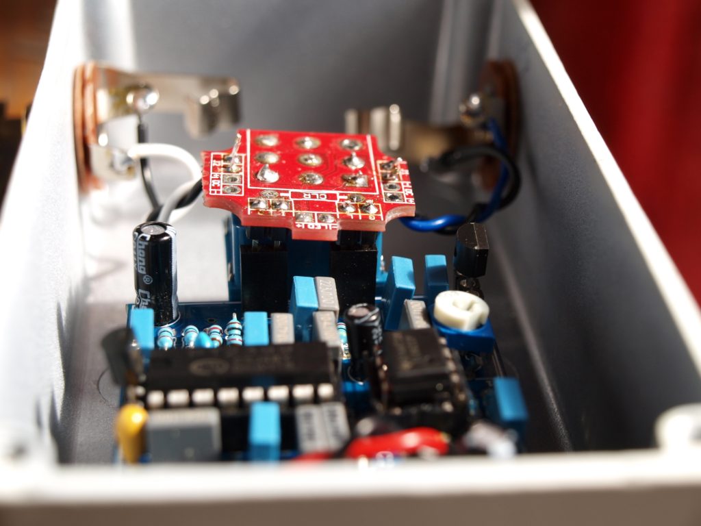
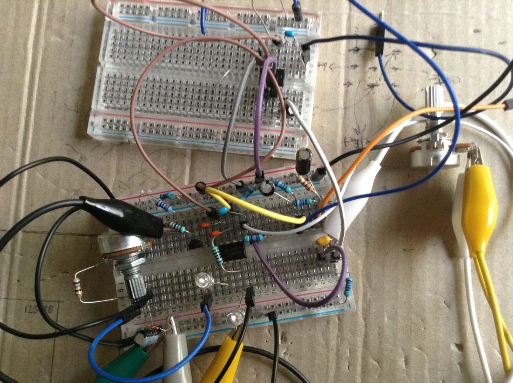
I was using the flat edge to judge polarity, but the legs were telling a different story. 

I then went through all the LEDs I got in that batch (yes, a cheap eBay buy from China).  The blue and red LEDs have the flat edge on the longer leg... the yellow and white LEDs have the flat edge on the shorter leg. 

So I guess I've learned two things - look at the leg, not the flat bit on the body... and don't buy cheap eBay LEDs from China? 
#48
Open Discussion / Punk death of a 70s console
March 05, 2017, 11:16:55 PM
Thought this story might interest some people around here - what happened to the mixing console used in one of the first punk recordings in the 70s. 

http://www.abc.net.au/news/2017-03-06/the-saints-im-stranded-mixing-console-mystery-solved/8327034

(Have to admit, I'd probably have done the same thing...)
#49
Build Reports / Current Lover build
February 05, 2017, 01:10:57 AM
Just finished up a Current Lover - first pedal I've managed to finish and box for months. 

It's pretty much a stock standard build - only small changes I made were to use the rate indicator as the 'effect on' LED, and wired the flange/matrix switch off board, because I couldn't handle it not being in line with the knobs.  OCD FTW. 

I've used smaller 3.5mm sockets for the send/return loop. 

Thanks to Govmnt_Lacky for pointing out I had a cap in backwards, which would explain why it was leaking brown liquid.   :-[

I've tried a white Tayda enclosure on this one, with sticky printed plastic.  Damn these white enclosures show up every little bit of dirt that I managed to get stuck on the back of the plastic.  I'll have to be neater next time.  Sprayed with a few coats of clear on top. 

Tayda aluminium knobs, which personally I'm not impressed with - I can't get them to tighten and stay level.  The grub screws don't seem to be centred, and the knob twists as you tighten.  Maybe I'm just doing it wrong. 

This pedal is for my kid again, so we've gone with a Simpsons theme.  The Ned Flan-diddly-anger is born. 


#50
General Questions / Burst capacitor
January 29, 2017, 10:01:10 PM
I got out a finished Current Lover this morning to think about boxing it up.  I've had it sitting on the shelf in a plastic bag for about 2 weeks.

I noticed some brown liquid in the bag.  Uh oh.  Turns out one of the capacitors has bulged up on the end and is leaking. 

I'm assuming this is a bad thing.  I should replace that one huh?

The weather has been quite warm here this last few weeks, would that have done it?  Should I be checking all my other builds and stock?  Or is this just something that happens occasionally for random reasons?

#51
I'll be running a pedal building workshop at a conference in Brisbane (Australia) in December.  It will be a basic introduction to electronics, and then build a simple distortion or fuzz face on breadboard to take home with you.  Followed by info on where to buy components, enclosures, PCBs, etc, and where to find help from friendly people - i.e. this forum.   ;)

Anyone in Brisbane area might want to check out the conference:  http://auc.edu.au/createworld/sessions/.  It is aimed at creative types.  They've also talked me into running a session on Arduino and music, so time to brush up on my MIDI commands. 

Has anyone here run pedal building workshops before?  I'm interested to see if you think I'm trying to cram too much into an hour and a half.  I've done programming sessions at conferences before, but this will be the first electronics / pedal building one I've tried. 
#52
Build Reports / Germanium fuzz build
October 23, 2016, 02:42:57 AM
This weekend's project was finishing a FaceMaster germanium fuzz from diyguitarpedals.com.au with some AC125 transistors.  Thanks Paul - sounds good!

The PCB is seriously small - made to fit in tiny enclosures.  So of course I stuck it in the biggest box I could find.   :o

I had a metal box that a watch came in - thought I'd try that out as an enclosure.  It wasn't great to work with - the drill tended to tear or bend the thin metal, rather than cut a nice clean hole.  The knobs aren't mounted parallel as a result, as the top of the enclosure is bent around the holes. 

Finished by going nuts with black then silver spray paint.  Originally was going to call it "Fuzz Space" but the name "Galactic Fuzz" seemed to stick in the end. 


#53
Introductions / Hi from Canberra
September 29, 2016, 08:20:51 AM
Hi, I'm Matt, from Canberra (Australia). 

I got into pedal building this year, started out as I was too cheap to buy a pre-made distortion pedal for my kid, and went from there.  Had fun building my way through some schematics from runoffgrove.com earlier in the year, and more recently found 1776effects, and from there this forum.  Have also found diyguitarpedals.com.au recently, hooray, and Australian source for stuff. 

I'm trying to get all my pedal builds written up on a blog somewhere - will put it in my signature once it is ready.  :)

Next big project is to build a bass guitar from scratch.  I've done furniture before, but I think a guitar may be a bit more of a challenge.  It may end up being a very pretty doorstop.  Or even a very ugly doorstop.  Anything is possible. 
#54
Build Reports / Auto wah build - Ducky von Quackenstein
September 26, 2016, 11:04:06 AM
One I finished recently - kind of a mix between the Dr. Quack and the Nurse Quacky.  I breadboarded the Nurse Quacky first, then added some of the bits back in from the Dr. Quack, such as the normal/bass switch, and used a TL071 for an input buffer.  Yellow LEDs of course, to go with the duck theme.

Knobs are decapitated bath toys.  I think it cost me $1 to get 10 of them.  My kid was a bit distressed when I cut the head of three of them, he has 'saved' the other seven from my evil scissors.  He still enjoys the pedal though.  :)

Short video demo - http://graybloomfield.com/guitar/2016/09/04/ducky-von-quackenstein/ducky/


#55
Hi,

I've done a few electronics projects over the years, but just getting into pedal making. 
In every other electronics area that I've worked in, convention seemed to be that the DC power plug/socket is centre(tip) positive, with outside negative. 

*After* building about 6 pedals for my kid, I realised that pedals seem to be wired with DC centre negative.  For compatibility with popular pedals of the past? 

So... should I rewire all the DC plugs on the pedals that I've done so far?  Will my kid turn up with his pedals and find he can't plug them in to anyone else power supplies?  Or is it acceptable to have either way?  :-\

Just wondering if it is better in the long run to rewire the pedals I've done already.  (And also rewire the power supply too!)

Ta,
Matt.