News:

Forum may be experiencing issues.

Main Menu
Menu

Show posts

This section allows you to view all posts made by this member. Note that you can only see posts made in areas you currently have access to.

Show posts Menu

Messages - PMowdes2

#46
General Questions / Re: Sharkfin alternative
April 04, 2019, 10:52:55 AM
Quote from: bsoncini on April 03, 2019, 09:30:22 PM
Never built it. But there is this.

https://www.deadendfx.com/product/f1sh

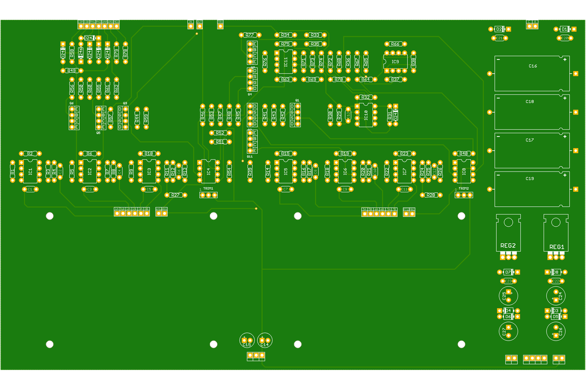
I was never quite satisfied with our version, I should not have used multiturn trimmers because dialling it in is a bitch, also I think that there was some mention of an error with one of the transistors from the original tracing that has been perpetuated down the years including in our design.  The S&H works but it's a little lacklustre and the autowah is nowhere near as good as something like the frostwave funk-a-duck or the Meatball.

#47
 BuGG has the hot cake

www.pedalpcb.com/product/awfulwaffle/
#48
Open Discussion / Re: EMS synthi Hi-Fli repair
March 09, 2019, 09:06:31 AM
Quote from: skyled on March 09, 2019, 08:54:05 AM
Please tell me that the diode ladder won't use smd diodes. It sure looks like smd in that picture.

Afraid so, only way to keep the size down to something less than a football pitch.  We are thinking of getting these fabricated assembled, it will add some additional cost but a whole lot less headache
#49
Open Discussion / Re: EMS synthi Hi-Fli repair
March 09, 2019, 08:48:40 AM

Here's a progess update

The top board which is the psu and phaser


One of the two identical diode ladders


And the pedal preamp


Just the bottom fuzz / vibrato board to go
#50
Open Discussion / Re: EMS synthi Hi-Fli repair
February 25, 2019, 04:25:51 PM
Quote from: JustALittleSolderBoy on February 25, 2019, 02:25:22 PM
Quote from: PMowdes2 on February 14, 2019, 11:24:02 AM

We got this bro, we've generated cleaned up versions of the schematics in the service manual based on Brent's photo's.  And we are in the process of putting them into Eagle so we can make some pcb's.  Once we have everything checked over maybe we can answer your questions.  You are mad trying to do this on vero though :)

Hi Phil,

only want to ask for an update - how is the progress regarding Your Hifli schematic?

Are You ready to answer my questions?

Regards!

We have finished the schematics and i'm in the process of laying out the pcb's.  It's slow going not least because I have no idea what size enclosure I can get it into.

Drop me a PM and i'll see if I can answer some of your questions

Phil
#51
Quote from: Bio77 on February 19, 2019, 06:38:09 PM
Quote from: PMowdes2 on February 19, 2019, 08:19:49 AM
I'm glad you got it working in the end, it looks awesome, I hate it when people have trouble with our boards.  I have to admit I have a bunch of stuff that I need to go back to and tinker with.  Dino seems to just be able to nail all of our proto builds and I sadly have a bunch of stuff on the "calibrate later" pile.  Think I should just stick to Eagle.

Do you mind if I nab the pictures for our Instagram feed???

Thanks, I just ordered another one.  I have a feeling I'll need to build one for a friend once they hear it  :D  Sure, nab away.  If you need me to email you anything, that's fine too.

Quote from: rockola on February 19, 2019, 11:20:00 AM
Received my PCBs yesterday. Placed an order for MN3204s with Utsource a moment ago - fingers crossed. Assuming they will arrive one day, is there any way to test the chips short of just trying them in a completed build?

I was wondering the same thing this morning.  Also, I'd be curious to know how to tell the difference between different op-amps.  I did notice that when I put the OPA2134 into the LFO, the triangle wave output had a larger amplitude than the TL072.  I'm not sure if that matters but that's why I chose it.

www.instagram.com/deadendfx
#52
Build Reports / Re: Ludwig Phase II
February 25, 2019, 02:52:05 PM
Quote from: DLW on February 25, 2019, 01:30:05 PM
I'd be honored!

www.instagram.com/deadendfx
#53
Build Reports / Re: Ludwig Phase II
February 25, 2019, 08:45:08 AM
Quote from: DLW on February 24, 2019, 11:52:10 PM
Recently completed a Ludwig Phase II Synthesizer. PCB from Dead End FX https://www.deadendfx.com/product/ludwig-phase-ii

The build guide for this project is superb. The pedal fired up on the first try and the tuning was easily accomplished by following the instructions in the guide. The biggest challenge (and it was a big challenge) was the off board wiring. There are a lot of wires that run between the board, switches, and jacks. Since one board mounts to the enclosure and the other mounts to the back plate, I used mostly stranded wire for its flexibility. I'm more accustomed to solid core wire, so the strands fought me getting them through the PCB holes. Also, there are several points that require 2 (and sometimes 3) wires in 1 hole. To make this easier, I soldered a short 16ga wire in the hole and used it as a standoff to solder multiple wires.

The original unit is a monstrous cabinet with an expression pedal that folds out. Adding a expression pedal to this clone is doable, but it's not something I really wanted. Instead, I added a 10kB pot to the side and put on a large knob that I can toggle with the side of my foot. It works reasonably well for me. I'm not a performing musician. I just make weird noises in my room.

The art was intended to capture some of the original design elements- mainly the icon and the burled wood finish.

Here are the box and gut shots...


Great job, do you mind if I borrow your photo's for our Instagram feed??
#54
Quote from: Bio77 on February 19, 2019, 12:29:19 AM
Quote from: RDL68 on February 18, 2019, 11:50:13 PM
Bio77, When I did mine last year, I bought working MN3204's from UTsource too.
I also bought some C4570's from them at the same time, which worked, but seeing you've mentioned your C4570's from there were fake, it's possible the ones I got from them were fake too. Possibly they're a similar opamp with the same pinout.


Maybe fake was the wrong wording, definitely the one in the LFO was not working. Definitely the 2SA1015Y and one of the 2SC1815(Y) were not working.  I'll have to test the rest out to know for sure. 

Quote from: Bret608 on February 18, 2019, 09:48:42 PM

You know I have to ask, how do you like the sounds compared to the A/DA you built?

I'm excited about this one, I'd like to do the calibration once more to get it perfect, then test it with the band.  I use a boss BF-2 with my bass, which I like.  I think this one is more of that flavor vs. the A/DA, and hopefully a better version of that.  The intensity foot switch is cool, I'm looking forward to having it as an option.

I'm glad you got it working in the end, it looks awesome, I hate it when people have trouble with our boards.  I have to admit I have a bunch of stuff that I need to go back to and tinker with.  Dino seems to just be able to nail all of our proto builds and I sadly have a bunch of stuff on the "calibrate later" pile.  Think I should just stick to Eagle.

Do you mind if I nab the pictures for our Instagram feed???
#55
Open Discussion / Re: EMS synthi Hi-Fli repair
February 14, 2019, 11:24:02 AM
Quote from: JustALittleSolderBoy on February 14, 2019, 08:43:35 AM
Quote from: bsoncini on February 13, 2019, 10:54:19 PM
Vero layout of this thing? You are nuts

Yepp - vero! Maybe I am nuts, but I have no knowledge in designing proper pcb boards and in tools like eagle and such. So vero is the only way to go for me - unless there is a pcb available. My etching pcb experience is " too basic".

At the moment the layout of my phaser board is 52 rows x 94 holes. There are different versions of the fuzz board - the smallest is 52 rows x 76 holes.
The pedal board is 9 rows x 21 holes and so it should fit into every Crybaby-like wah shell.
The numbers of rows of both the larger boards is equal, because I intend to mount them like a sandwich. I don't plan to make a seperate wiring board for the pots and switches - parts of these are on the fuzz and phaser boards and some parts will be soldered to the pins of the mounted switches and pots.

Some parts are obsolete and will be hard to get: the N558V/NTE778A should be a standard 1458 dual opamps. EMS themselves used LM1458 in later versions of the Hifli. I think about using NE5532 instead.

But other parts are more tricky:
C746 (A6, A16 fuzz board) are almost inpossible to get - I think about LM194H/LM394H metal can devices here. I thought about matching my own FETs with a PEAK DCA70 and make some clamps from metal sheet myself...
For TIS70 (A17 fuzz board) maybe a BFS21A is worth a try?
What whould You use for 7474 (A9 fuzzboard)? Is it a HD74LS74A?
The  2N5163 FETs will be hard to get, but there a lot of possible candidates to try -  5458, 2N3819, 5958, BF245A(GSD), MPF-102(DSG), 2N3822, KP303I, BFW11,
BF245A (GSD), 5458 (GSD). So pinout may be changed on the boards.

There are some points in the service manual where I am not certain due to the poor quality of the manual. I refer to the pdf-file from http://jbemond.free.fr/SDIY/EMS/EMS_Hifli.pdf:

1) The center pole of the SW3 modulation switch (SP3T) connects to #20 of the wiring board schematic. From there it should go to the unreadable # on the phase card schematic (lower right corner of the schematic in the pdf). From there it goes to R23 2,7K. But where from there? +12V or -12V?  The handwriting there is unreadable...

2) In the fuzz card schematic there is a R108 to LED1 #8 (near lower left corner of the schematic in the pdf). The resistance of R108 - 3,3K?

3) In the fuzz card schematic there is a R105 below D15 near R108, R106 & R107 (near lower left corner of the schematic in the pdf - connects to transient vibrato too). The resistance of R105 - 27K?

4) There are pictures of the phase board where a wire goes from #20 of the phase card some where around A2 (Dual Opamp) on the phase board. Is it really A2 and where exactly leads the wire to and is there another resistor (resistance?) added?

5) There are pictures of the fuzz board where a wire jumps from #13 to A10 (3080) on the part side of the board. Where does the trace near the 3080 lead to?

6) In the schematic of the fuzz card (the upper right side) it is quite hard to read the traces around #22, 21, 19, 18, 20 and just below the 5-6-7 opamp triangle of A5 and Q1 (BC169C) around Q10 (10uF tantal) and the 470K to +12V. It is hard to decipher, what is a connection and where traces cross each other only. Maybe someone has a readable schematic or high quality pictures of the solder and part sides of the boards?

Maybe some of these questions may show my stupidity in Your eye, but as I told You before - I am a total newbie when it comes to electronics.

Any hints or comments, folks?

We got this bro, we've generated cleaned up versions of the schematics in the service manual based on Brent's photo's.  And we are in the process of putting them into Eagle so we can make some pcb's.  Once we have everything checked over maybe we can answer your questions.  You are mad trying to do this on vero though :)
#56
Open Discussion / Re: EMS synthi Hi-Fli repair
February 13, 2019, 11:36:19 PM
Ok, got all the schematics done except the controls board.  Time to start getting stuff checked over.
#57
Open Discussion / Re: EMS synthi Hi-Fli repair
February 07, 2019, 12:54:54 PM
Quote from: bsoncini on February 07, 2019, 12:53:12 PM
I'll try to prop it up tonight.

I don't have a tripod

No worries, and thanks for trying.  Dino and I will go over the schematics and board images we have and see what we can do with what we have got.
#58
Open Discussion / Re: EMS synthi Hi-Fli repair
February 07, 2019, 12:46:55 PM
Quote from: bsoncini on February 07, 2019, 11:53:07 AM
I can try to take other photos if you want but it'll probably be the same since my only camera is a smartphone.

I tried to see if I could scan the boards. It worked ok but I can't get the board flat with the headers in place

Can you prop the board up so at least the board is flat??  Would that work??  or at least if you are using the camera hold it steady with a tripod and move the board underneath, that way the scale and angle of view are consistant
#59
Open Discussion / Re: EMS synthi Hi-Fli repair
February 07, 2019, 10:43:10 AM
Quote from: Yahoo67 on February 06, 2019, 11:15:52 AM
Lol i love all this detective work ^^ maybe we are seeing the birth of a futur deadend effects project :)

I had a go at overlaying the board images last night and it was a little tricky since the camera wasn't fixed and the perspective / scale changes slightly.  It should be doable, but it is going to take some time.
#60
Open Discussion / Re: EMS synthi Hi-Fli repair
February 06, 2019, 10:41:10 AM
Quote from: bsoncini on February 06, 2019, 10:11:57 AM
Pics sent. Let me know if you need any help tracing it or verifying values for you

Maybe we should start a thread at diystompboxes on this? Get more people involved in it

Thanks, I will have a look at them tonight.

I'll leave it up to you about the thread on DIY.  I think there is probably enough experience on here to make some progress on this so long as you are happy to poke about with a multimeter and check continuity for the bits we cant figure out from the photo's