
I'm going to build myself an attenuator using a L-pad to tame my Dr Z maz 18. I've learnd that when attenuating a signal you loose highs and the schematics I follow use a 2 pole on-off-on "treble"-switch (2 diffirent caps) before Lug 2 of the L-pad (to filter out bass?). I was thinking i could use a potentiometer to blend one small and one large capacitor instead of the on-off-on switch. Unfortunatly I dont know how to execute this. Could someone tell me how this should be wired? What pot and cap-values that might work?
- Welcome to madbeanpedals::forum.
This section allows you to view all posts made by this member. Note that you can only see posts made in areas you currently have access to.
#1
Tech Help - Etcher's Paradise / Blending 2 capacitor values with a pot?
October 04, 2019, 10:00:17 AM #2
How Do I? Beginner's Paradise. / Help me modify this schematic.
September 18, 2019, 05:47:46 AM
Hi, I want to build myself an attenuator and i will follow this guide https://guitar.com/guides/diy-workshop/diy-workshop-build-your-own-attenuator/
I would like to modify the treble-switch they include in the project
Instead of a switch with two caps I would like to have a potentiometer to increase the treble, how would I do that?
I would like to modify the treble-switch they include in the project
Instead of a switch with two caps I would like to have a potentiometer to increase the treble, how would I do that?
#3
Build Reports / Firebird project
September 18, 2019, 04:50:08 AM
Havn't been active on this forum for a couple of years. Mostly because I havn't really built any pedals but focused on family. However I have built myself a SG-style guitar from kit. After that succesul project I ordered custom part and assembled a Jazzmaster that became my number one guitar. Last three years I've been obsessed with the idea of building a Gibson Firebird clone and this year I finally started the project. From januari through july I more or less spent all hours in my garage after the kids went to bed. Here are some pictures of the process.
<iframe width="480" height="360" src="http://s1282.photobucket.com/user/markusJklein/embed/slideshow/Firebird"></iframe>
there are more photos and videos of the build-process on my instagram: markus.johansson.klein
<iframe width="480" height="360" src="http://s1282.photobucket.com/user/markusJklein/embed/slideshow/Firebird"></iframe>
there are more photos and videos of the build-process on my instagram: markus.johansson.klein
#4
Open Discussion / Attenuator treble bleed?
November 13, 2017, 12:26:06 PM
So I have a dr Z Maz 18 that is waking my childran and pissing of my wife every evening. I was thinking it'a time to build me a L-pad attenuator to quiet things down.
I'm probably going to make on following this guide: http://www.theguitarmagazine.com/diy/diy-workshop-build-your-own-attenuator/
In the schematics they have wired a on/off/on switch with two capasitors to act as a bright/off/brighter switch. I was first thinking I would replace this with a 2-pole rotary switch and wire up 5-6 capasitors but then I was thinking it might be better to wire a capacitor blend pot. What do you guys think? Is it ok/safe to this setup, how would I wire it and what would be good cap valurs?
Thank you /Markus
#5
Tech Help - Projects Page / Polarised caps in position of non polarised cap
February 25, 2015, 12:49:37 PM
Hi, i'm assembling a monster fuzz and i've order som wrong parts. The BOM calls for 0.22uf non polarised caps but i accidently ordered polarised. None of the legs connets to ground so I cant figure out wich way to solder them. Are there any specific rules I could follow here?
#6
Build Reports / 9 months project finished
August 19, 2014, 12:08:17 AMMy better half finished this on this saturday, she fired up right away and we couldn't be happier!
#7
Build Reports / "remote-controlled" Looper-thingy.
May 28, 2014, 08:18:05 AM
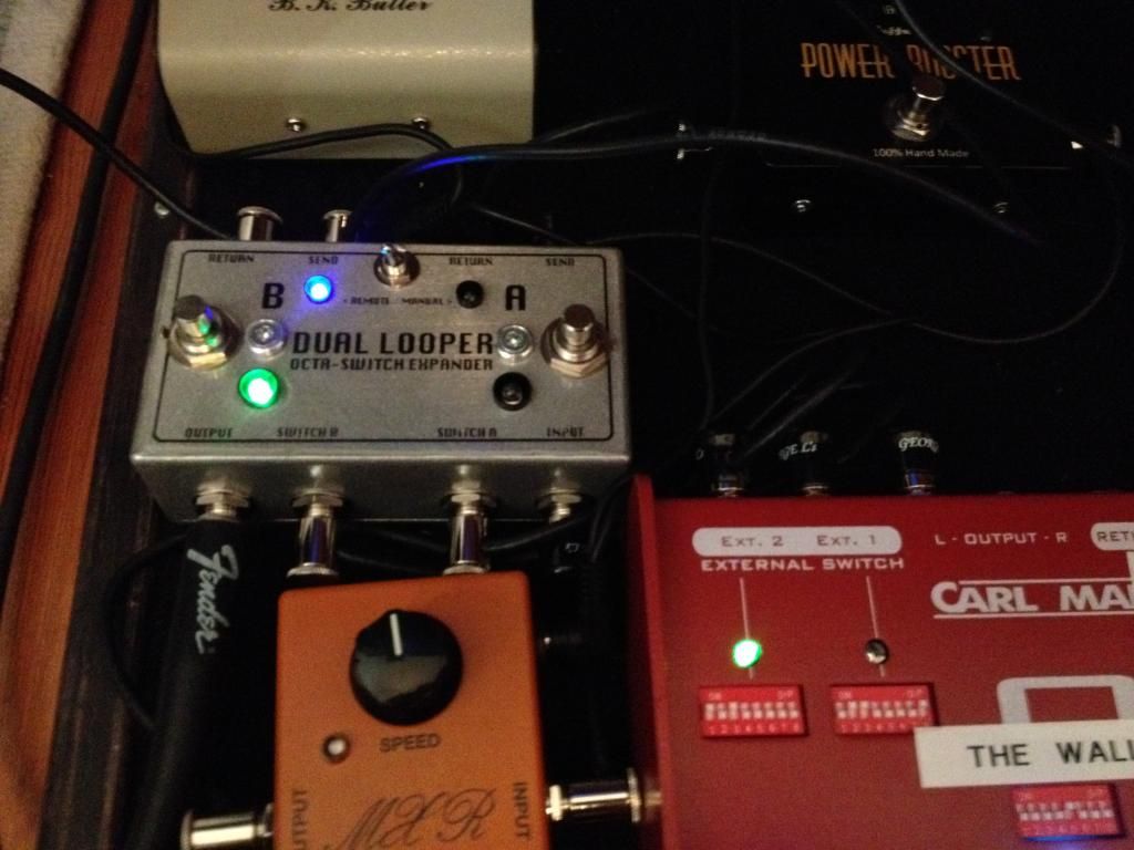
The Pedalboard I'm in the process of making will house about 5-6 more pedals more than I have in on floor at the moment, so I figured I need more control! I want to use the 2 external switch-jacks on my Carl Martin Octaswitch II to control a loop-pedal with 2 FX-loops... this would expand my octaswitch into a 10-loop-pedal. Aside from that, it would also let me place these extra 2 loops before or after the 8 main loops and still let me place pedals in series between the 8 and 2 extra loops.... make sense?
here's the result.


I also added a toggle that switches between "remote" and "manual". Manual lets me use the stompswitches.
Here's a example on how it works. For those of you who are new to the octaswith I'll give you a quick tour. there are 8 switches (9 if you count bypass) each have 8 dipswitches to set which of the 8 loops should be active for that stompswitch. there are also 2 sets of 8 dipswitches for the 2 "external switch"-jacks (to switch amp-channel for example). In the example below I've used this setup:
Guitar > Octaswitch > Phase 90 > "DIY 2 channel looper" > Amp
and in the looper channel B is the Tube Driver, channel A is power boost
Switch B active:
Switch A active:

Both on.

here's the result.


I also added a toggle that switches between "remote" and "manual". Manual lets me use the stompswitches.
Here's a example on how it works. For those of you who are new to the octaswith I'll give you a quick tour. there are 8 switches (9 if you count bypass) each have 8 dipswitches to set which of the 8 loops should be active for that stompswitch. there are also 2 sets of 8 dipswitches for the 2 "external switch"-jacks (to switch amp-channel for example). In the example below I've used this setup:
Guitar > Octaswitch > Phase 90 > "DIY 2 channel looper" > Amp
and in the looper channel B is the Tube Driver, channel A is power boost
Switch B active:

Switch A active:

Both on.

#8
Open Discussion / NEW PEDAL DAY! I'm so happy I could cry!
May 22, 2014, 12:04:54 PM
Finally... I've been waiting since july 30 and now my life is complete!
I'm so happy I could cry....


I'm so happy I could cry....


#9
Tech Help - Projects Page / TQ2-L-5V how to I use it?
May 19, 2014, 11:44:49 PM
looking at the datasheet just confuses me. http://pewa.panasonic.com/assets/pcsd/catalog/tq-catalog.pdf
I need straight forward instructions/tips on how to hook this up. To Explain what I will be using it for, check out my older topic here http://www.madbeanpedals.com/forum/index.php?topic=14051.msg130471#msg130471
What I have figured out about the relay:
I think it should be used "single side stable" (?)
pin 1: +5V (using 78L05 and battery when testing)
pin 2: Jumpered to pin 9
pin 3: guitar input
pin 4: FX send
pin 5: ?
pin 6: ?
pin 7: FX return
pin 8: output to amp
pin 9: Jumpered to pin 2
pin 10: switching signal (ground) from tip of jack.
Does this make sence?
Thankfull for any help I can get
#10
Build Reports / new pedalboard in the making. Oiled up, getting there
May 16, 2014, 12:18:47 PM
So I had vision... turned into a model in Sketchup..
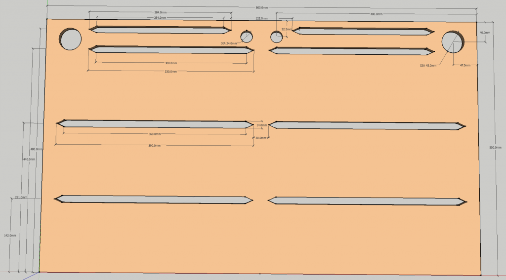
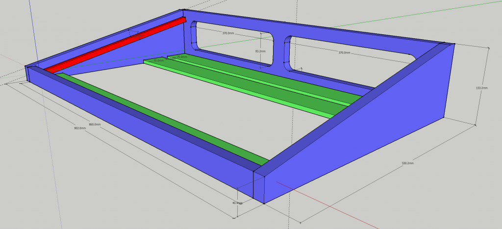
Got some walnut wood for about 120$
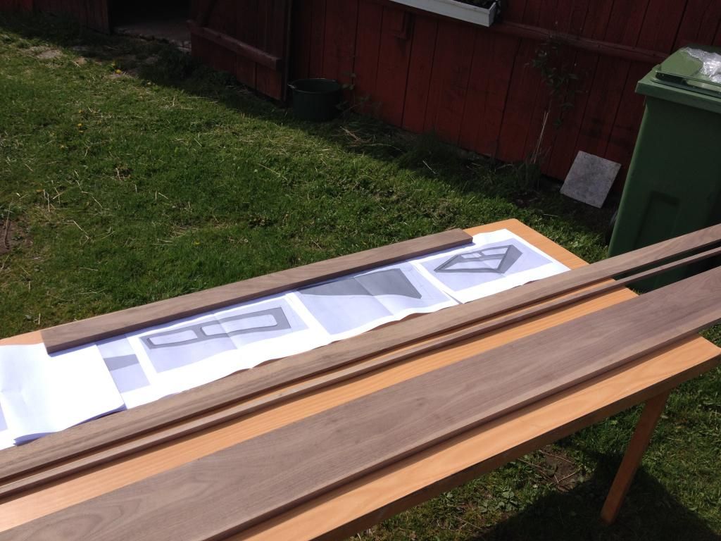
And called my dad and Uncle...
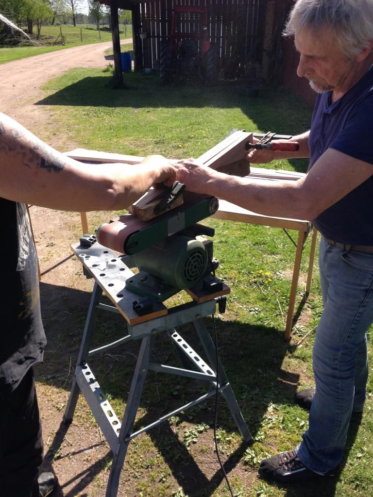
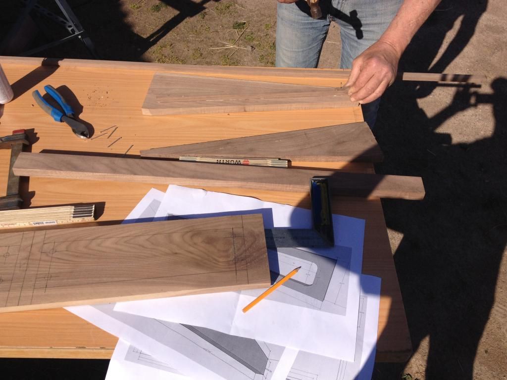
And its getting there...
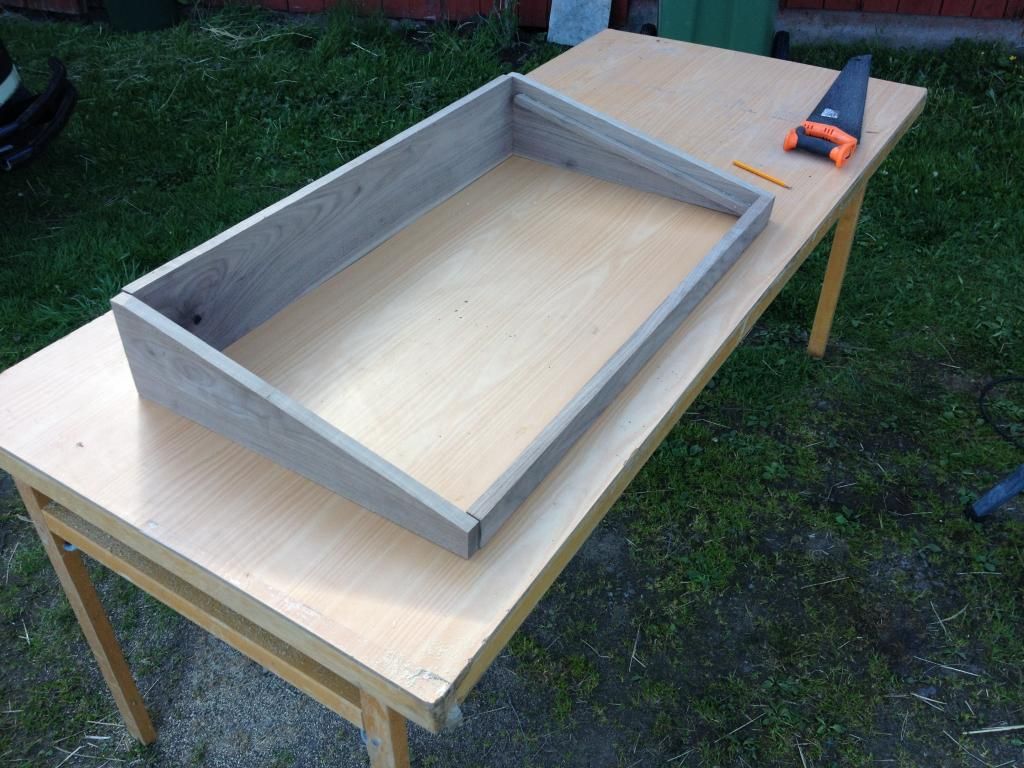
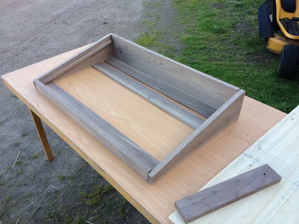
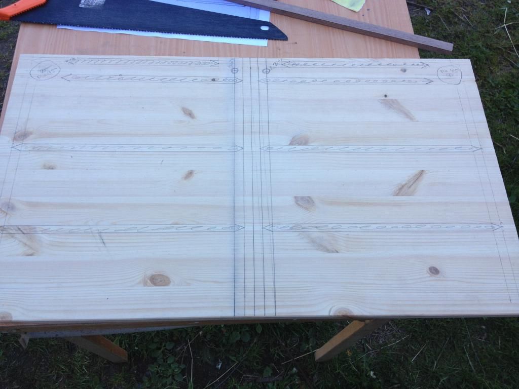
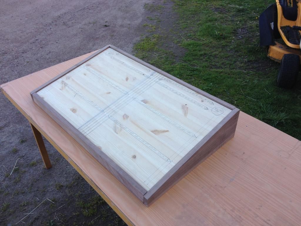
Within a couple of weeks I will be drilling and sawing the top board, sand everything, assemble the frame and mount jacks, glue velcro on the top etc, etc


Got some walnut wood for about 120$

And called my dad and Uncle...


And its getting there...


Within a couple of weeks I will be drilling and sawing the top board, sand everything, assemble the frame and mount jacks, glue velcro on the top etc, etc
#11
Tech Help - Projects Page / loop-pedal controlled by external switch?
February 22, 2014, 04:26:40 AM
I have a Carl-martin octaswitch, it has 8 loops and 2 "external switch" outputs for controlling amp-channels for example. I was thinking that i might be able to build loop pedals with I/O for guitar/amp and send/return for effects but on/off would be controlled by the "external switch" outputs of the octaswitch instead of a foot-switch. this would give me 10 loops instead of 8.
Please give me your input on this idea. How would you tech-heads construct this?
Please give me your input on this idea. How would you tech-heads construct this?
#12
Tech Help - Projects Page / loop-pedal controlled by external switch?
February 22, 2014, 04:15:48 AM
I have a Carl-martin octaswitch, it has 8 loops and 2 "external switch" outputs for controlling amp-channels for example. I was thinking that i might be able to build loop pedals with I/O for guitar/amp and send/return for effects but on/off would be controlled by the "external switch" outputs of the octaswitch instead of a foot-switch. this would give me 10 loops instead of 8.
Please give me your input on this idea. How would you tech-heads construct this?
Please give me your input on this idea. How would you tech-heads construct this?
#13
Tech Help - Projects Page / Zero Point SDX ticking
October 12, 2013, 11:38:04 AM
I built a zero point a while ago and had some issues with it but put to the side for a while (4-6 months!) but now I would like to finnish it. I keep hearing a slight ticking that relates to the speed-knob when the mod switch is turned on. Any Idea's where I should be looking? so far the only thing I've done is switch IC5 but that didn't work.
#14
Open Discussion / Can anyone Identify this strat?
September 12, 2013, 02:50:45 AMIt's not a very good picture but anyway
#15
Build Reports / Little Green Wonder
October 03, 2012, 12:08:42 PMA little perfboard little green wonder I put together. Havn't really had the time to play through it a lot yet but it sounds killer! It will probably be my new tubescreamer on the board. The enclousure is a PPP Emerald green.


#16
Tech Help - Projects Page / Honey dripper audio path?
August 17, 2012, 01:19:30 AMBuilt a Honey-dripper yesterday and while trying to rock it before I box it I'm not getting any juice out of it, its dead silent. Since I havn't "built" any audio probe what i usually do is cut the outputwire from the board and start poking around with it along the audio patch.
The problem is I can't really follow the schematics for this circuit, It's a little to advance for me. So could anybody give me any direction on the audiopath? where should I poke around? Is there anyway I can identify broken IC's whit just the audio-"probe".
/Markus
#17
Tech Help - Projects Page / perfboard Rump Roast
July 14, 2012, 03:57:59 AM
I'm trying to build a perfoboard rumproast but I'm having trouble understanding things here. This is my second try at this and so far I just completed the powersection, T1 and sockets for Q1, when I hook this up to 9V and tryng to Bias Q1, just the socket, my 50K T1 just goes from 8.47V - 8.51V. This was the problem with my first completed perfboard. Am I missing something here? I'm using ver.1 schematics.
#18
Tech Help - Projects Page / Phase 100 not working
June 24, 2012, 03:14:53 AMA friend of min have a broken MXR phase 100 that I am trying to get working but I think I might need some help with this one. My best guess is to start looking somewhere in the powersupply section casue it just doesn't power up. My friend use a little poweradapter that goes from 3 to 12V. the adapter has a little indicator-light that goes off when I plug it in to the phaser. So my best guess is that something shortcircuets.
Any ideas where I should start?
#19
Build Reports / No name 4 in 1
May 10, 2012, 11:37:30 AM
This is what I've been up to for the last couple of days.
effect order is:
Buffer - AMZ PCB
Egodriver - Madbean PCB (these is a DAMN good project! third one built)
Pharaoh Fuzz - GGG muff board
Neovibe - GGG neovibe board
Powered with a AMZ power supply PCB
All FX are powered with 9V except the Neovibe, it has 22V
FX order can be changed with patchcables if needed. All wires between jacks and 3pdt boards are shielded and all so the I/O of the muff fuzz. I used a board even for the 3ptd toggle switch that works the optional buffer. The orange led to the left pulses with the speed of the neovibe.
For the lightshield I used tiny cut mirrors that I glued together, The Glass-worker charged me 3$ for a bunch of them.
Now to the decal Since I had shouldersurgery 6 weeks ago and haven't been able to work with my right arm I had lots of time to draw this one up in photoshop. Emailed it to a company that engraves aluminium and had it made for the fare price of 40$.

Uploaded with ImageShack.us

Uploaded with ImageShack.us

Uploaded with ImageShack.us

Uploaded with ImageShack.us

Uploaded with ImageShack.us
effect order is:
Buffer - AMZ PCB
Egodriver - Madbean PCB (these is a DAMN good project! third one built)
Pharaoh Fuzz - GGG muff board
Neovibe - GGG neovibe board
Powered with a AMZ power supply PCB
All FX are powered with 9V except the Neovibe, it has 22V
FX order can be changed with patchcables if needed. All wires between jacks and 3pdt boards are shielded and all so the I/O of the muff fuzz. I used a board even for the 3ptd toggle switch that works the optional buffer. The orange led to the left pulses with the speed of the neovibe.
For the lightshield I used tiny cut mirrors that I glued together, The Glass-worker charged me 3$ for a bunch of them.
Now to the decal
Since I had shouldersurgery 6 weeks ago and haven't been able to work with my right arm I had lots of time to draw this one up in photoshop. Emailed it to a company that engraves aluminium and had it made for the fare price of 40$.
Uploaded with ImageShack.us

Uploaded with ImageShack.us

Uploaded with ImageShack.us

Uploaded with ImageShack.us

Uploaded with ImageShack.us
#20
Requests / BJF Candy Apple Fuzz
April 25, 2012, 09:42:25 AMAnybody know of any schematics of this one?