News:

Forum may be experiencing issues.

Main Menu
Menu

Show posts

This section allows you to view all posts made by this member. Note that you can only see posts made in areas you currently have access to.

Show posts Menu

Topics - Rockhorst

#21
Here's a finished Liquid Eternity chorus, based on the Arion SCH-1. Differences are minute: I kept it mono and added a rate led. The sound is 100% identical to the original. I designed this pcb a while ago, but never got to populating it until a few weeks back. It's the second iteration of the pcb, first one had a wrong connection. I'm thinking of a final revision that moves the pots downwards a bit on the pcb to balance it a bit better. The moment of intertia on the lower side is a bit high, which causes the pcb to tilt. I think it will be fine, but it puts stress on the solder joints of the pots. Pictures:


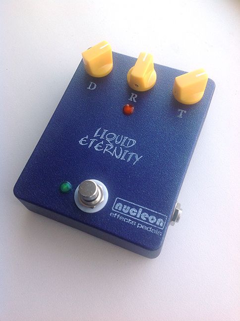
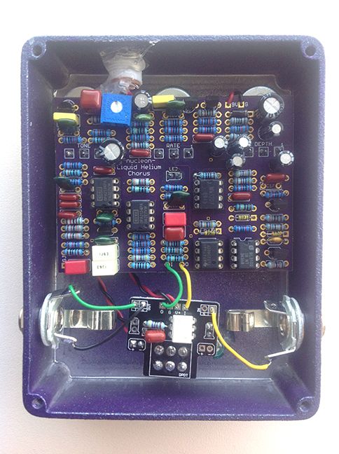
As you can see, I originally called it the Liquid Helium. Wasn't too fond of the name. When Ayreon's The Source came out two months back, it renamed it the Liquid Eternity in it's honor. I'm not going to go into details, but it has to do with the storyline of the album. Best album of the year, I don't expect anything to top it (at least in the metal world) this year. Allow me to plug it here:


If anyone's interested: there's one more pcb before I have to order more. Shoot me a pm.
#22
Build Reports / Flabulanche
May 14, 2017, 07:47:27 PM
I've had this PCB around for a while, decided to finally build and box it up. The holes on the pcb for the switch are a bit tights, I didn't have a switch with pcb pins, so I butchered a switch with loops instead. Fired up the first time, although I disliked the first sound test. Very shrill sounding. Turns out I had biased Q3 at 1.3 V and didn't spot the dot. Rebiased at 13V it sounds a looooooot better. Reminds me a bit of the plexi drive (but nicer). I think I prefer the compression switch on 'high'. If I were to build it again, I'd probably hardwire that in. Can't fault the color scheme, love it. I got a custom stamp made with my MXR-spoof logo. Looks really nice IMO. Here's the inside and outside:


p.s. lots of other builds coming up soon ;)

#23
First off: I'm not looking for another debate on ROHS and lead-free vs leaded solders. :)

On topic: I solder with Stannol HF32 for my own builds but I also do repairs on ROHS pedals. It supposedly is not a good idea to mix. I usually just clear the joint as good as possible and resolder with leaded. When I was researching lead-free solder options a few years ago I stumbled upon SN100C as the best option, but I couldn't find it anywhere for hand soldering use (only bars for solder baths). Yesterday I came across a Dutch website that sells something called SN100 Ni+, which is Tin with traces of Nickel, Germanium and Copper. It seems to be the same stuff as SN100C. It has no-clean-flux at 3.5% which is the same as in the leaded Stannol. Anybody ever used it that could share their experience? Thanks :)
#24
I've 'designed' a double pt2399 delay which for a large part can be build on a Deathklaw board. Basically I find the Deathklaw has too much filtering which makes it sound dull and dark. I like to run my delays really subtle, more atmospheric type settings and adding 'depth' to solos. That means the delay level is quite low and noise should be low enough on the first repeat (but can distort more on 2nd). I'm not The Edge, more Adrian Smith you see :). I understand Brian's choices but I think his previous versions were better sounding, with just a little more noise, for my intended use. Also, I find the mix control goes from nothing to unusable in about 20% of the pots turn. So, here are some mods:

R5 15k -> 22k (as Brian has suggested, bumps the output up to unity gain, should really be in the build doc)
R23 2k -> 1k

C5 15n -> 4n7
C6, C7, C13, C14 2n2 -> 1n5
C20 47n -> 15n

Solder 2k7 (anything from 1k to 4k7 gave me nice results) across lugs 1 and 2 of the mix knob. This alters the taper and gives more control in the first 70% of the turn. Full on is still the same. Alternatively, just use a log pot (50kA) for this. I had to fix this afterwards and this was less hassle for me.
#25
Open Discussion / PPP enclosures for cheap!
May 02, 2017, 10:37:11 AM
I didn't see anyone mention it (but I haven't been religiously checking the boards either) but it seems PedalPartsPlus (PPP) has new owners. They are getting rid of old stock for bargain prices IMO: a 1590B in a random color for $3 is a steal (that's cheaper than they are in bare aluminum). I ordered a bunch and named some color preferences. I'm very pleased with the box that came in the mail so ordered another batch. They're selling fast I heard, so if you want so, head over :)

(no affiliation with PPP, just pointing you towards a good deal :) )
#26
It's been a while since I checked. I'd like some 1590BB's in nice colors. It's hard to beat PPP's quality but shipping and taxes is killing. My net price for a shipment of 10 powder coated boxes is about $35 per box! Anyone in the Netherlands or Europe doing quality stuff for reasonable prices and shiping?
#27
I've posted this question a while ago and Brian was kind enough to answer promptly. However, the topic seems to have disappeared and I don't remember the answer.

I'd like a bit more of a hifi quality to the repeats of the Zero Point SDX2 in analog mode. Possibly, this could be done by filtering out some more lows? Brian pointed me towards a certain capacitor, but which one was it? I've also tried comparing various Zero Point schematics, but though they are similar in structure, the component values vary quite a bit. Sorry for the repost, hope someone can help me out for the second time.

Also, which components should I jump to bypass the tone control completely?
#28
A few years ago, Ben Coles and Stevie1556 offered some powder coated enclosures shipped from the UK. Major saving compared to PPP international shipping (to the Netherlands for 10 boxes, including taxes and the abismal state of the Euro, it totals at about $25 per enclosure which is ludicrous). I'm having a hard time reaching Steve. Banzai and similar companies offer boxes, but only in very basic colors. Also, the Banzai ones are 'bulk' which means they are full of dings and splotches. I've tried that once, totally not acceptable.

Soooooo...the question is...anyone know a good supplier with reasonable shipping and a nice choice of colors? Or should I just start saving $300 for some boxes.
#29
This is just to double check:
I'm building a fixed resistor L-pad box for a 5W amp. I was under the impression that I should use isolated jacks, but I've only seen other builds that use non-isolated jacks. So connecting the grounds through the chassis of the box is ok?
#30
I recently visited a small 1 hour workshop on solving the Schrödinger equation with straight forward computer programming (take small steps to integrate second derivative to first derivative and then first derivative to wave function). It inspired me to take up something that has been on my 2-do list for about two years now: learn to program in Python and do some physics simulations with it. I finally found a book on computational physics specifically for Python, written by Mark Newman. The chapters containing the basics are available online for free. Chapter 2 contains most of the info needed for simple math programs.

I'm doing the exercises in the book but to get some more exercise I started doing some problems from Project Euler. Some of the problems really force you to produce an efficient algorithm. I find it highly addictive. You read a problem and think "I can do this", write down some lines of code only to discover that brute force programs take a looooong time to run.

In the past two days I solved problems 1, 2, 3, 5, 6, 7, 8 and 10. Time races past and I should turn off my computer for the next couple of days if I want to get anything else done during these holidays ::)

So, is anybody else doing these? A little math background goes a long way, which is also why I don't think I'll solve more than 25 of these problems. By then I hope to be doing physics, not math ;)
#31
In the beginning of October I bought a 2015 American Standard Stratocaster. These are incredibly well made guitars IMO. Fender really has its act together at the moment. The only thing I disliked were the Custom Shop Fat 50s pickups. The bridge and middle pu were fine, but the neck just sounded bland and lifeless to me. So I asked Timbo to wind a modern Strat set. He suggested combining Alnico II and Alnico IV magnets and wound them pretty hot (8k5 bridge, 7k7 mid and 6k7 neck). I wired these up with a master tone control (33 nF cap) and a series blender for the mid and bridge to get a sort of humbucker.


It's absolutely glorious. The neck pickups is nice and full, plenty of bottom end but also a lot of high end sparkle. And it's loud. I think I could almost gig with just that one pickup and playing with the guitar's volume a bit. I'm not a big fan of just the mid pu by itself on any strat and this time is no exception (it's a good pu, just not my fav strat position). However, together with the neck however you get very nice, stratty funk tones all around. The bridge is crazy hot if you just look at it's DC resistance, but it actually balances very well with the neck. I even had to lower the neck and raise the bridge a bit to even their level. It's nice, firm and trebly without any 'ice pick'. Blending the the mid pickup in series with the bridge actually kills a lot of the highs, more than I anticipated. Could be due to the 250k pot or it's just the nature of that setup. Not really suited for cleans, but it does work nicely with some gain (somewhere between a bridge and neck humbucker...guess that was to be expected). It's a nice flavor to have on board and could make it very versatile when switching amps. I'll have to take it out gigging and see how it works. I also put on a mint green pickguard.


The pickups made a nice, but bland guitar into something that has me grinning from ear to ear and makes me wanna rock out. So, highly recommended. I'm not done modding by the way. I ordered a deluxe bridge with pop in arm and some locking tuners. Basically, I'm turning it into a Deluxe, which may be a bit silly ;)
#32
I made two HM2 pedal with The3SecondRule's Swedish Chainsaw V1 board. It's the 4 knob version that I 'converted' to 5 knob: the low control became the mid control, the level and low pots were wired off board. Sorry for the bad photo quality, there's currently not a lot of light around even during the day. iPad cameras suck at low light conditions.

This white one is 'stock'


This blue version has some mods: soft and hard clippers are LEDs, the germanium diodes were jumpered. I also slightly changed the center frequencies of the tone controls:

  • Low 330R became 470R with 1u cap (didn't have 1u5, both white and blue have this)
  • Mid 6n8 became 8n2
  • High 330R became 390R


Gutshot of the blue one. The white one has tidier guts but I wasn't able to photograph those anymore. I can say that shielded wire on the blue made no difference on noise level though (compared to non shielded on the white).


Finishing them was a bit of a PITA. The boxes were powdercoated by Stevie1556. To achieve the colored lettering I sprayed some regular rattle can on there and covered with black/transparant vinyl sticker. Didn't work out as good as I had hoped, not going to do that again. Especially since the clearcoat reacts with the spray paint, making it run from under the sticker. Hence the bleed on the white/orange and the 'drop shadow' attempt at a cover up on the blue one. Oh well. Originally, I was going to make two white ones. One of the boxes got caught by the drill, which messed up the powder coat. I filled it up with spray and marker and then really found out the clear reacts with the rattle can spray. Here's the result of that clusterf**k:


Soundwise, I don't think the modifications to the tone stack are that radical and not very noticeable. With all the knobs maxed there certainly is a difference in sound between the two units. The white one nails 'that one sound' perfectly, but also feels kinda nasal. The blue one has a bit more clarity and would probably cut through the mix better in a band situation. My guess is that this is mainly due to the bridging of the germanium clippers. It would be worth it to make this a switchable mod IMO. It's funny that the pedals sound identical with all the knobs half way at 12 o' clock though.

Here's a quick sound demo to illustrate, recorded with a Sony Linear PCM recorder. I used a stereo setup with an 18W Blues Breaker on one end of the room and a modded Epiphone Valve Jr. on the other end. The recorder was set up in between. The slight delay effect is from a TC Flashback.

Link to demo
(not able to use SoundCloud at the moment)
#33
Sorry, I realised this topic should've been in member projects, so I moved it.
#34
Build Reports / Retrograde with big knobs :)
October 11, 2014, 08:33:18 PM
Built an Octavia fuzz on a Retrograde board. Massive, massive fuzz. The fuzz control is actually quite useable throughout it's sweep, from overdrive like tones to a big wall of fuzz with some sputtering. Could've been boxed in a much smaller enclosure, but the guy I built it for had expressed interest in these knobs quite a number of times...And they do look very good indeed :)

#35
Build Reports / OC71/OC47 Tonebender
September 06, 2014, 03:48:55 PM
Meet Bender ;D


After putting it off for way too long, I finally decided to build a Tone Bender on a MBP Pastyface board. The build took me three hours, including drilling and transistor testing. Fired up the first time. There's a Road Rage in there for the -9V. I mixed some component values of the Sola Sound and the Soulbender based on educated guessing. It absolutely rips, so I'm definitely going to document the component values for future reference. It is nice, full, creamy and aggressive if it needs to be, but not as wooly as a Fuzz Face. I took it to my two fuzz-aholic friends at the local guitar shop and they both ordered a copy within 10 seconds of playing. Mind you, these guys audition every fuzz pedal that goes through their shop, so I guess there's something good in there 8)

Q1 is an OC71 from my late grand dad's stash, Q2 and Q3 are OC47.

I fiddled with the bias knob, but I'm not really sure what I should be looking for. It sounded great about everywhere (but I keep the fuzz knob mostly maxed).
#36
Just to be save: I'm not in any way affiliated with either of the products mentioned below. I do occasionally repair effects for a local guitar store and this is done purely out of curiosity (theirs and mine). Ok, here we go.

I've always liked my 1Spot power supply and from what I've read, RG Keen committed a great deal of research time to the 1Spot. Now recently, local Dutch pedal designer Dr.No has released a switching power supply. There's been quite some debate about it, since people discovered the brand sticker on the unit could be removed and revealed it to be a possibly rebranded el cheapo Stagg power supply. Some claim that it was a labeling mistake at the factory and that the unit is actually different from a 'real' Stagg. The jury is still out on that one. I expect to have a definite answer by the end of the week (waiting for a Stagg unit to come in for comparison). But to keep me entertained, I hooked both unit up to an oscilloscope (settings: 0.5 us/div, 50 mV/div). Here's the results:

1Spot


Dr.No


To my untrained eye, the 1Spot signal looks a lot cleaner compared to the Dr.No, which has a lot of extra junk (resulting in a somewhat fuzzy picture). What I'm unsure about is how much you would actually notice of this in practice. My guess would be that less junk is better, the cleaner the power going in, the less potential for noise, whistling and what not. Anybody with some more experience with power supplies and scope signals that can shed some light on this issue?
#37
I'm trying to fix a Mesa V-twin. The pedal is in good shape and most everything is working. When tapping the right footswitch to switch between the blues and solo channels, the LED changes but not the gain. I had found a schematic which I've temporarily uploaded here:

Mesa V-twin

If you look at page 5 you see that the channel switching is handled by Q3 and simply uses a jFET to parallel a resistor to change the gain of the opamp. The base of Q3 is connected to a diode (see page 6). Measuring at the diode shows a voltage of -128 mV when one channel is selected and over +1V when the other is selected. The voltage switches rapidly from negative to positive but then slowly rises to a constant value. No change in sound is heard. Measuring the resistance in the negative feedback loop of the opamp gives a resistance of 91 kOhm, consistent with a 100k parallel with a 1M. So basically, it's stuck in blues mode.

From these observations it seemed to me that the switching circuit was mostly functional and that the most likely culprit was the Q3 transistor. However, replacing it made no difference at all. So, I'm at a bit of a loss right now. Any and all suggestions welcome! Thanks :)
#38
Posted this on DIYSB, thought I might as well post it here too:

I've got an old German phaser unit that isn't working. When I turn it on it does pass a guitar signal but no phasing happens. The copper tracks have some corrosion on them but I didn't find any continuity issues. The LFO light bulbs don't light up but are still working (tested them out of the circuit). When in circuit, voltoge over them is very low.

Here's the schematic:


My main suspect is upper one of the two 2n1613 transistors, which is connected to the bulbs.

DMM reads: C: 26V, B: 1.3V and  E: 0.8V.

The other 2n1613 shows: C: -7.4V, B: -7.8V and E: -8.6V. This transistor feeds the on/off indicator bulb which is working fine. The minus sign is slightly confusing (measurements taken relative to the same ground point).

I haven't checked any caps or the opamps yet, as the bulbs not lighting up seems to indicate that the problem isn't in the audio section.

Any and all help and suggestions welcome. If there's any measurements that need to be done, let me know.
#39
General Questions / Stupid filter question
January 26, 2014, 07:14:18 PM
So look at this picture


I totally get how both can work as a high pass filter: for high frequencies the capacitor is basically a short and for low frequencies it's an open circuit. About the opposite for low frequencies. In the bottom circuit, the pot impedes high frequencies to escaping through the capacitor.

For the top circuit the cut off frequency is calculated by RC, the product of the resistance and the capacitance. Is that the same for the bottom circuit?
#40
Build Reports / Stargazer 1590A
December 08, 2013, 01:23:38 PM
My first 1590A build pedal build! I've done things like a Road Rage in a 1590A before, but this is the first real pedal! Now, it pales compared to some 1590As I've seen in this place, but it's a start. It's a 1-knob Fuzz Face with Germanium OC141s.