News:

Forum may be experiencing issues.

Main Menu
Menu

Show posts

This section allows you to view all posts made by this member. Note that you can only see posts made in areas you currently have access to.

Show posts Menu

Messages - JakeFuzz

#16
Ahh you're right. All the most recent diagrams were lost! Ill try and repost them later today. This is the original thread:

http://www.madbeanpedals.com/forum/index.php?topic=2172.15

The diagram you have should be accurate. If the detune feature is working (and the detune pot?). There must be some kind of problem either with the CD4093 oscillator or the transistor. Just a quick glance on the CD and transistor voltages look fine (ill check closer later). Do you have access to an oscilloscope? You may want to scope out the top leg of R1 (that connects to C3) if you can.
#17
Open Discussion / Re: DIY Minimoog!
May 14, 2015, 11:07:35 AM
Quote from: monkeyssj1 on May 14, 2015, 04:03:07 AM
Paul i'm somewhat interested in your enclosure as well :). Please let me know updates/if you plan on being down to do some for others (enclosure/faceplace or even just faceplate.)

Ill maybe start a new thread in misc. diy when I get this thing going. I am not sure how economical it would be to source out the enclosure. I am literally just buying a Hammond box and drilling holes in it. The faceplate I am just drawing up in inkscape and sending to a laser engraving company who does the engraving and punching.
#18
Open Discussion / Re: DIY Minimoog!
May 13, 2015, 02:47:44 PM
Quote from: peAk on May 13, 2015, 12:50:37 PM
Quote from: JakeFuzz on May 13, 2015, 12:46:58 PM
http://search.retrosynth.com/ah/search/lookit.cgi?-v9901.2166

Looks like you need a frequency counter and a multimeter. I have a scope with a frequency measure function that I am going to use for the oscillator calibration.

Thanks Paul, just the kind of info I was looking for.

Please update this thread with anything else you find/realize/etc. and I will do the same. I will also be curious what enclosure you go with. I read through the Muff Wiggler pages and saw some of the ones people were thinking about.

Sure! This one is definitely going to take me a while to put together. So far I am thinking of a 17x10" aluminum chassis which will be raised and angled using maple slab side pieces. The back panel will be a thicker gauge aluminum or steel sheet which will hinge from the bottom to open. The face panel I may get laser engraved from BNP if they can do that size and if the price is right. 
#19
Open Discussion / Re: DIY Minimoog!
May 13, 2015, 12:46:58 PM
http://search.retrosynth.com/ah/search/lookit.cgi?-v9901.2166

Looks like you need a frequency counter and a multimeter. I have a scope with a frequency measure function that I am going to use for the oscillator calibration.
#20
Open Discussion / Re: DIY Minimoog!
May 12, 2015, 08:47:34 AM
We will probably go the panel route as well. Whenever I am playing synth I am always fiddling with the knobs way too much to have them that tightly spaced. Looking at one of the 17"x10" Hammond boxes with maybe a hinged back panel for the pcb. I am thinking of mounting all the trimmers on the backside of the pcb and just drilling holes in the back panel so I dont have to wade through the spaghetti to get it calibrated...
#21
Open Discussion / Re: DIY Minimoog!
May 11, 2015, 03:58:39 PM
This is so cool. I ordered one board for me and my synth friend to play with. I probably wont finish it for a while but I can't wait to hear it when its done. Always wanted a Moog since I played with my buddies Prodigy.
#22
Nice score! That one is super clean. Gibson amps are great finds. I restored a '63 GA-5T Skylark recently that sounds excellent. I got it on c-list for $100! The tremolo and slightly crunched up sounds on these things are incredible.
#23
Open Discussion / Re: Faceplates: Amp
April 06, 2015, 10:34:04 PM
Quote from: oldhousescott on April 06, 2015, 12:56:43 PM
Jeanne at BNP Lasers does great work, but really only takes CorelDraw files. If you've got CorelDraw, you're golden.
Sandy at PrecisionDesign lasers also does great work, and takes more input drawing formats.

Pretty sure Joe at amplates just does the design and sources the actual mfg to BNP. Or at least he used to.

+1

I've used BNP several times and they always do great work. Jeanne is great to work with. They were able to do my plates with a PDF exported from inkscape. They were roughly in the $30-50 range depending on size and the number of punched holes.
#24
I used to use Dunlop Tortex but I started using Lollar picks and can't see myself looking back anytime soon. Very unique sounding/feeling pick. Got one with a p-90 purchase and once it took on a good bevel I knew I had to order more.

http://www.lollarguitars.com/mm5/merchant.mvc?Screen=PROD&Store_Code=LGP&Product_Code=BagOfPics

:o Just checked and it looks like they don't sell them anymore!
#25
Open Discussion / Re: A cool switchless wah project
September 14, 2014, 10:46:30 AM
Wow this is neat!  8)

I've always hated the bypass switch on my wah pedals. Ill have to give this a closer look but it looks like he is using Zvex probe sensor circuit to trigger LDRs as switches. Cool!
#26
Build Reports / Re: A Klone for a Klon !?!
August 02, 2014, 12:21:56 PM
It's all good man! If I had a pedal that valuable I probably wouldn't be shipping it off either! I live in LA so I am sure one of these days ill run into someone who can bring one over for testing.

This thing looks beautiful as always. Those inset LED bezels look incredible; do you do that with a step drill? I love this combo on my board. Great for those singing almost clean tones  ;D
#27
Quote from: Cortexturizer on July 30, 2014, 01:49:00 AM
I am seriously considering selling my fender tele deluxe and investing into a Fano-like custom job at a local luthier's workshop.

Do it! That p-90 neck and Tele bridge combo is my favorite pickup config to date. So many great tones!
#28
This; and I dont even know how to play...  8)

#29
Open Discussion / Re: Klone Science
July 08, 2014, 12:52:40 PM
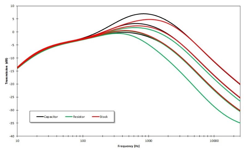
The resistor change is just the stock circuit shown in the previously linked schematic with the values of C21 and C23 switched.

The cap change is the stock circuit with the value of C14 changed to 8.2nF.

The stock circuit is is the previously linked schematic without any changes.
#30
Open Discussion / Re: Klone Science
July 08, 2014, 10:34:28 AM
Updated the impedance plot. Looks like input hovers around 2Meg then some inductive reactance comes into play. Output is around 450 over the range.

Here is a collection of the circuit changes made to Klones. Referencing this schematic:
http://1.bp.blogspot.com/-5aEPAyJYOzo/U4ice4jXIvI/AAAAAAAAHiw/7n5jViJkyIQ/s1600/KlonCentaur-Corrected-2009.GIF

The capacitor plots refers to the changing of C14 from 3n9 to 8n2. The resistor plots are a recently discovered potential error in the original schematic mentioned earlier where R21 and R23 are swapped. Sorry for the wacky colors; I didn't want to make three different plots so some things are overlapping but it is pretty easy to understand if you look at it long enough. Very big high end changes with the resistor swap. Gain is fixed at 50% and the treble control is shown at 25, 50 and 75 percent for each circuit.