News:

Forum may be experiencing issues.

Main Menu
Menu

Show posts

This section allows you to view all posts made by this member. Note that you can only see posts made in areas you currently have access to.

Show posts Menu

Messages - JakeFuzz

#31
Open Discussion / Re: Klone Science
July 06, 2014, 09:34:12 PM
Alan, I have a few other data sets for some of my overdrives but no fuzz. I'll try and get some of these together later this week. I can tell they are wildly different. My favorite modified lavache is especially interesting in that it has a flat frequency response and very strong second order harmonics. Cool sound.

Sdlogan I haven't done the ktr or the Klon yet. We are still working that out so stay tuned in the next few weeks for some really interesting stuff!

Keefe I am thinking of a namm far in the future and hearing "yeah he basically wrote the book on unicornocide" haha I love this hobby.

Rej dear god where did you get that ice spear?! Don't see those around these parts. Does that really hang off of stuff? That could kill you! Did you get a chance to try that resistor swap? I am on vacation right now but am going to test this out first thing in Monday. I sold a klone to a guy with a real Klon many years ago and he described that exact discrepancy with the treble response between the two.

Mkresol, yes definitely. CJ and I were just screwing around and poking fun at HAD and his ridiculous video with that crazy Kaiser fellow. I think if I really tried to put a pedal in our xrd the operator would throw a fit! Lol.
#32
Open Discussion / Re: Klone Science
July 06, 2014, 03:54:57 PM
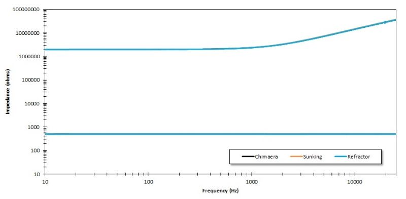
Guys I am sorry but after writing that I realize that the input impedance shown in the first plot is incorrect. I forgot to account for the current into the analyzer itself. It will be higher than that shown. Will fix it tonight!
#33
Open Discussion / Re: Klone Science
July 06, 2014, 03:40:52 PM
Yes I should clarify how the measurements are made.

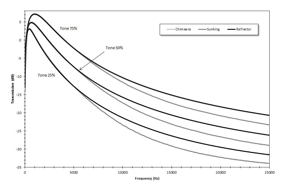
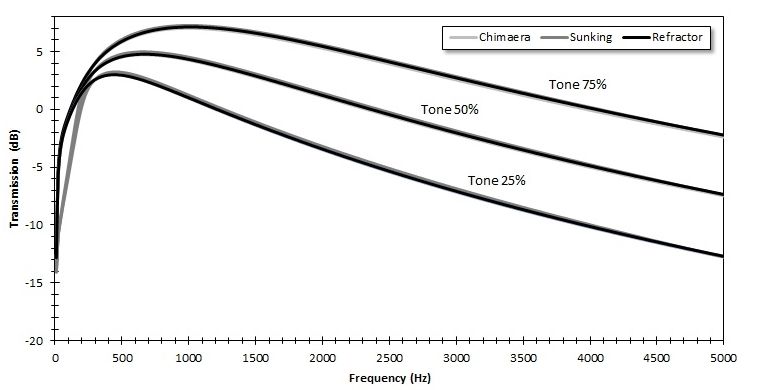
The frequency response plots are done using a two channel swept sine measurement. In this measurement we measure the voltage put into the pedal using channel one. We simultaneously measure the voltage output using channel two. What we plot is called the transmission because we are dividing the voltage output by the voltage input by the following.

G(dB)=20log(Vout/Vin)

You see now that the output is measured relative to the input so we say it is the voltage "transmitted" through the device under test. This is an especially handy measurement when the input impedance of the device is low or the excitation source is being heavily loaded.

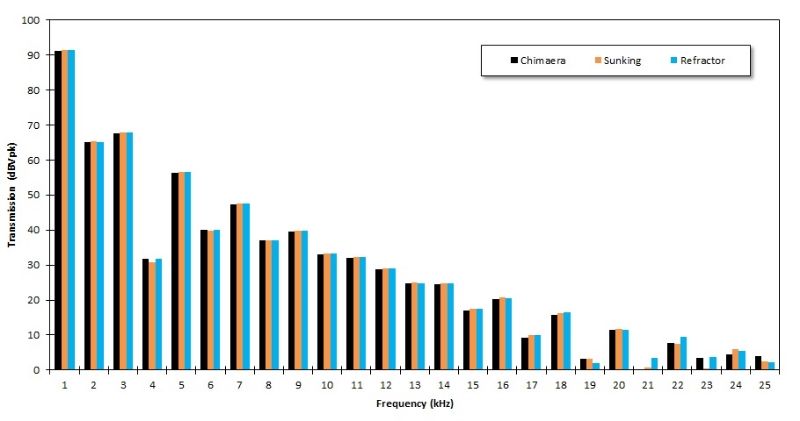
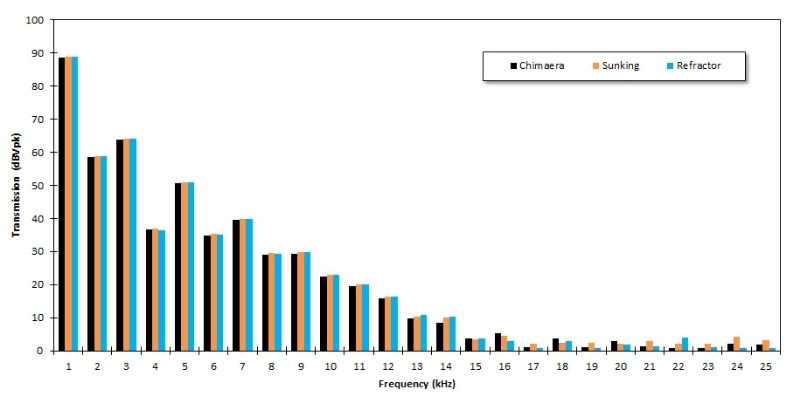
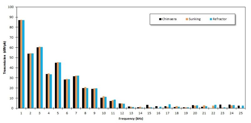
The fft mode is a little different and slightly more complicated. This is a single channel measurement where we measure the output voltage for a snapshot of time. This snapshot is fed through an algorithm called a fast Fourier transform. This transform takes this voltage variation as function of time and converts it into a frequency domain which is what we take as our output. You can analyze the harmonics generated by chopping off the tops and bottoms of our input signal by sending in a sine wave at a single frequency and looking at the magnitudes of the integer multiples of the input frequency that are in the output signal. The different ways we clip our waveform will create different peak ratios between these higher frequencies. Think of it as a distortion "fingerprint". Because this is a single channel measurement, the ratio of the output to input is not known. So in this measurement we just substitute a 1 volt peak to peak (Vpk) where Vin goes in the formula above. I shifted things around though to make it a little easier to read so the actual magnitudes are not real but the peak ratios are and these are what we are looking for in this measurement.

The impedance is measured using the two channel swept sine measurement but we are measuring the voltage across a resistor in series with the input or output. Because we know the resistor has purely real impedance, we can compute the current through it (and the series input impedance). We can then divide the measured output voltage by this current to get our input or output impedance magnitude.
#34
Open Discussion / Re: Klone Science
July 06, 2014, 06:08:56 AM
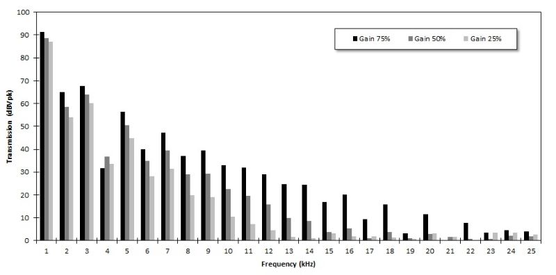
And last but not least these are FFT harmonic spectra of each circuit with a 1kHz 100mV amplitude input. These are taken with the tone control fixed at 50%. I have data for the other tone control values but they look the same. These are zeroed to a -107dBVpk noise floor (so thats not ~90dB of gain  :o).

Gain control at 75%


Gain control at 50%


Gain control at 25%


And again the impact of sweeping the gain on one circuit with the tone control fixed at 50%
#35
Open Discussion / Re: Klone Science
July 06, 2014, 05:55:22 AM
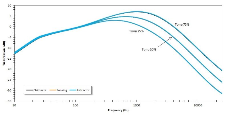
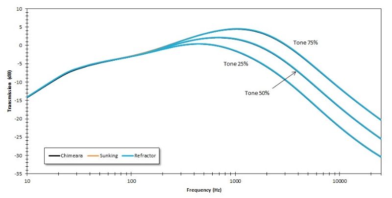
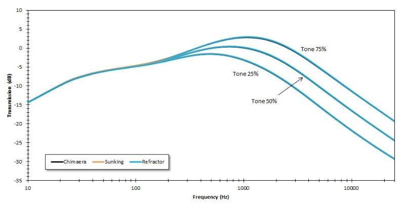
Frequency response plots:

Gain control at 75%


Gain Control at 50%


Gain Control at 25%


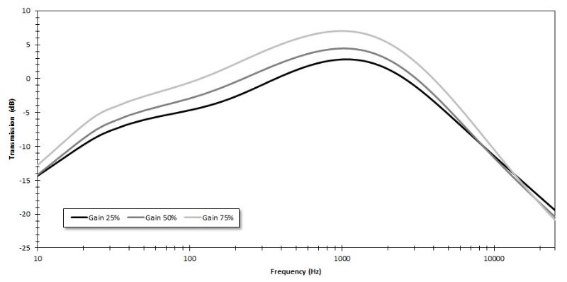
And because it isn't super obvious from the above plots here is a sweep showing one of the circuits with the tone fixed at 50% and sweeping the gain control.
#36
Open Discussion / Re: Klone Science
July 06, 2014, 05:43:43 AM
Done!

Picture bomb. Lets start with the the easy one. Input and output impedance.

#37
Open Discussion / Re: Klone Science
July 05, 2014, 02:26:37 AM
Sure Rej Let me ask the owner to make sure that's cool. I would be very interested to see what the values turn out to be. The ktr is smd right?

Misha, excellent suggestion. The plots look much better on a log scale. I also added color so its a little easier to see. Finishing up the last harmonic plots tomorrow!
#38
Open Discussion / Re: Klone Science
July 04, 2014, 06:00:25 PM
Yes very interesting. Thanks for linking Rej. While I have the SK back in the test enclosure I'll swap those resistors and take some frequency sweeps for comparison.
#39
Open Discussion / Re: Klone Science
July 02, 2014, 07:58:40 PM
Hehe so I figured it out. I am using polarized 1uf bypass caps in the post clipping gain stages and I reversed the polarity of one of them! Everything looks normal now. I will process the rest of the data this weekend and have it ready to go!
#40
Open Discussion / Re: Klone Science
July 02, 2014, 02:28:31 PM
Yep that is all coming. So I have 18 sets of data for each circuit; 3 tone settings and 3 gain settings. I have swept sine frequency analysis at each setting and FFT harmonic plots with a 1kHz sine wave input. I also have two additional plots for each one showing the input and output impedance as a function of frequency.
#41
Open Discussion / Re: Klone Science
July 02, 2014, 04:48:19 AM
From about 300Hz to 5kHz they are all pretty much the same (that is the Chimeara and the Refractor are right on top of one another). The differences below and above that range are quite large. The transmission (terrible name) is shown in a logarithmic scale.
#42
Open Discussion / Re: Klone Science
July 01, 2014, 02:25:52 AM
Yes but I also want to report data that is accurate and the discrepancies we see here I think are too large to attribute to transmission line losses or some weird additional capacitance. I don't think it would hurt to go back and repopulate the SK and run it through another time; it does have some additional capacitor switches which I may have hardwired incorrectly which could show what we see. Ill triple check!
#43
Open Discussion / Re: Klone Science
July 01, 2014, 02:00:42 AM
Uh oh. I think I done screwed something up! I went to go put the first frequency plots together tonight and the Refractor and Chimaera are right on top of one another (as expected) but the Sunking has some odd high and lower end behavior. I am thinking I may have messed up some of the switch hard wiring. I am going to repopulate tonight an maybe re-run the Sunking hopefully tomorrow night. What do you guys think? These plots are with the gain at 75% and at three tone settings. On another note is everyone okay with these plot formats?


#44
Open Discussion / Re: Klone Science
June 30, 2014, 07:04:46 PM
Ooh that's pretty cool! I have never seen anything like Spectra Plus before ill have to check out the demo software.

A long time ago I was playing around with the idea of building a serious pedal design/test rig with some National Instruments DAQ stuff. I think there must be a way to use their cheap USB DAQ systems and a Labview license to build a multifunction spectrum analysis tool. Those DAQ interfaces only cost around $200 (I think we have lots of them floating around my lab!). Ill look into it.
#45
Open Discussion / Re: Klone Science
June 30, 2014, 03:40:12 PM
Thanks Brian! I wish spectrum analyzers were cheaper so I could own one personally. They are an excellent tool for designing effects.

All the plots are taken I just need to put them together into easy to understand charts. I also took plots for my Kingslayer in different diode configs, an Apis with LM313's, A Fulldrive II, my Lavache, A Screwdriver clone and an EHX Soulfood. Those may come later as I process them. Very surprising results from just switching around the clipping diode types on the KS!