News:

Forum may be experiencing issues.

Main Menu
Menu

Show posts

This section allows you to view all posts made by this member. Note that you can only see posts made in areas you currently have access to.

Show posts Menu

Topics - cajone5

#21
Build Reports / Sonic Titan Vero
November 21, 2016, 07:51:07 AM
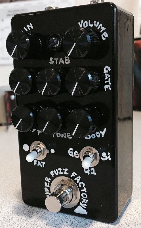
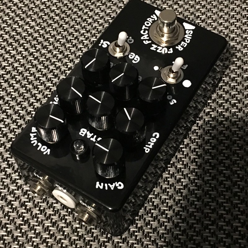
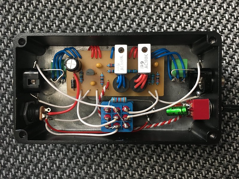
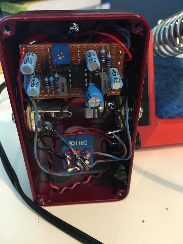
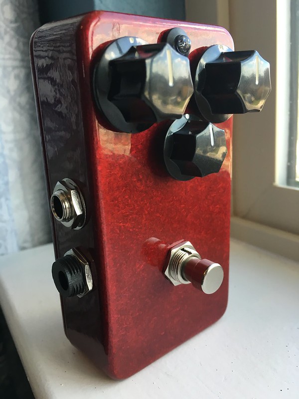
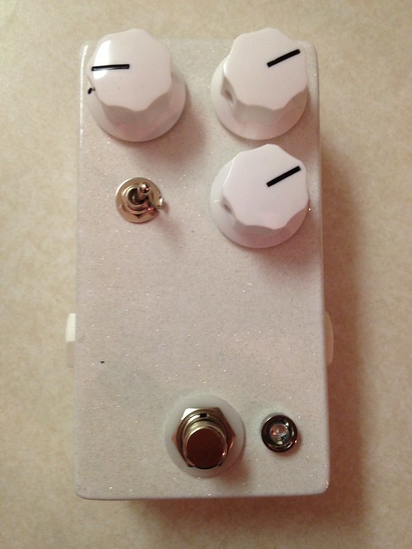
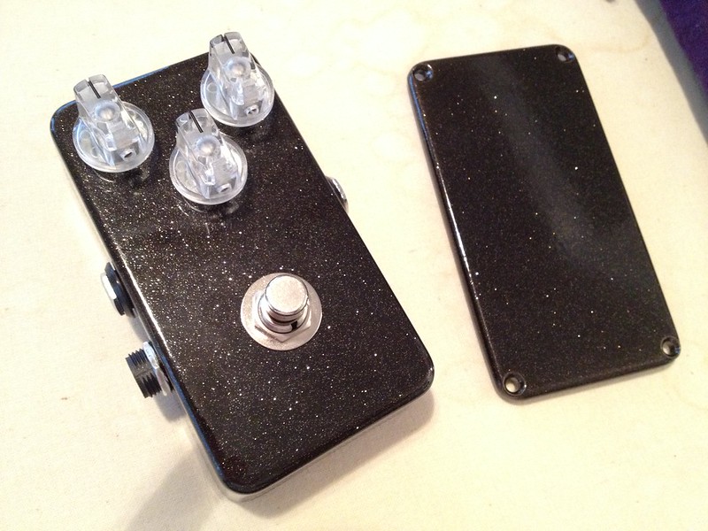
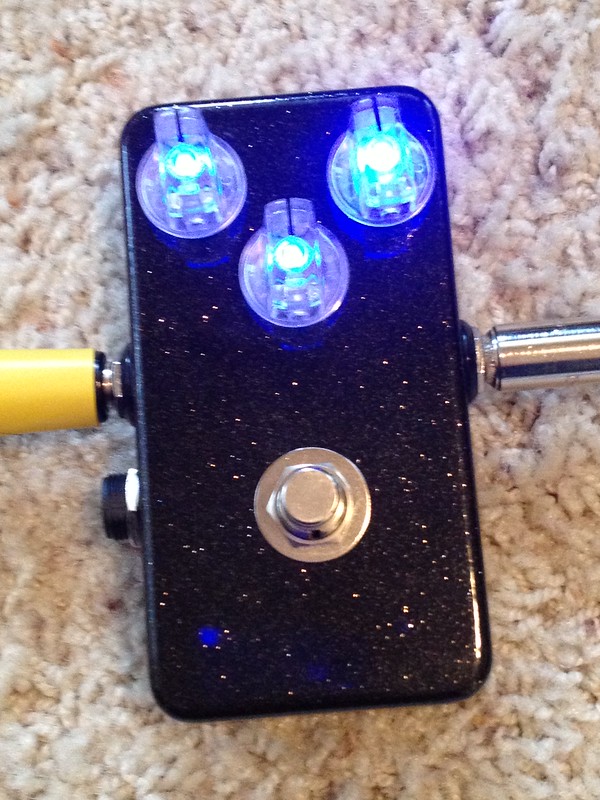
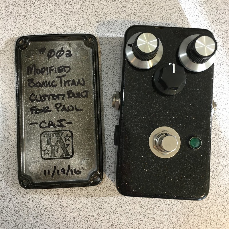
Continuing my productive building... this time it's a vero sonic titan. This is the third I've built and this one was built for someone as part of a trade.  I really dig this circuit.  I will eventually build a "mojo" one for myself.  Only mod on this one is swapping the gain pot for a linear taper to give more perceived range.


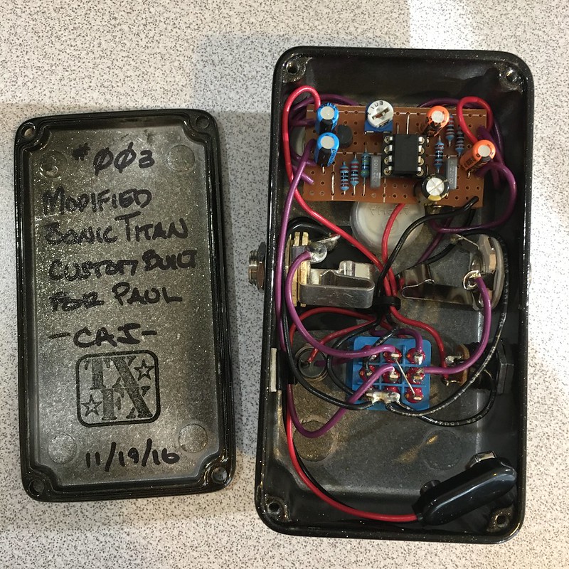
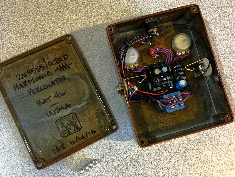
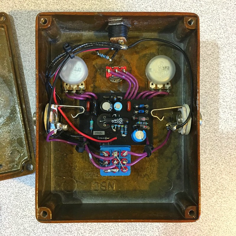
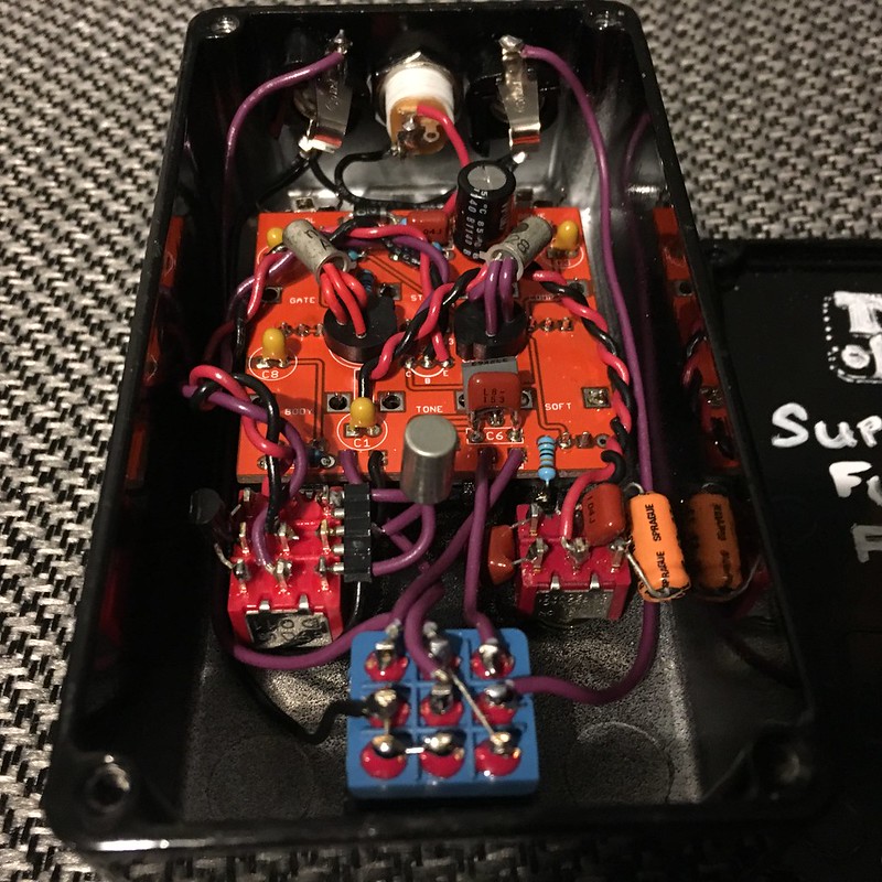
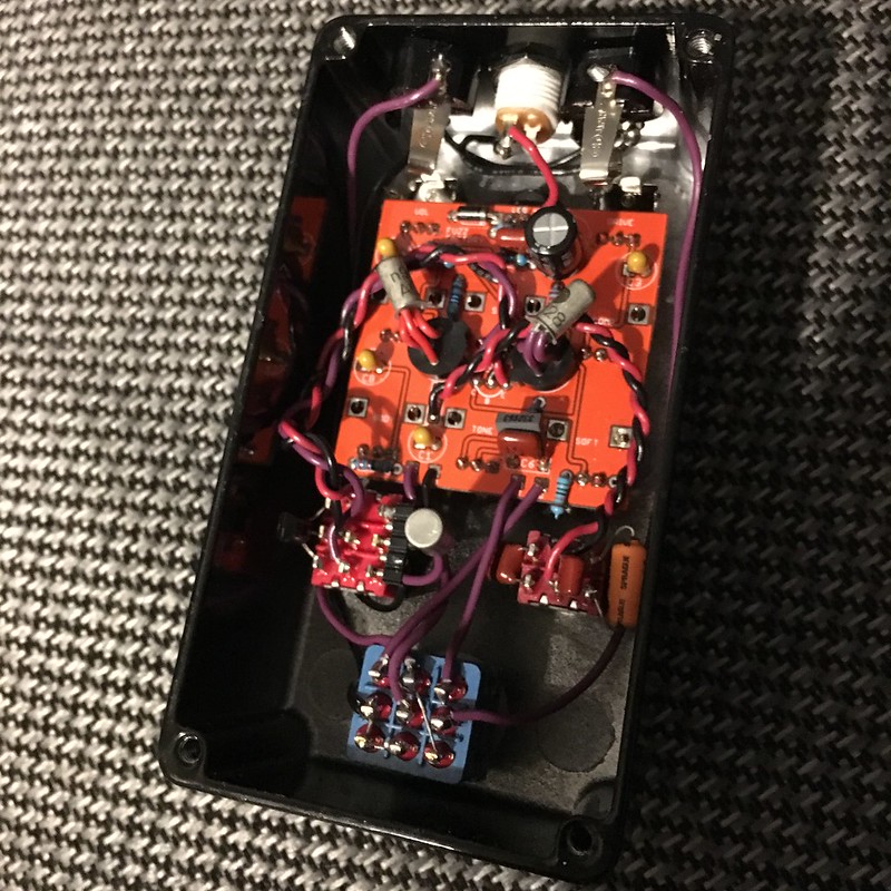
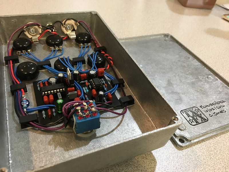
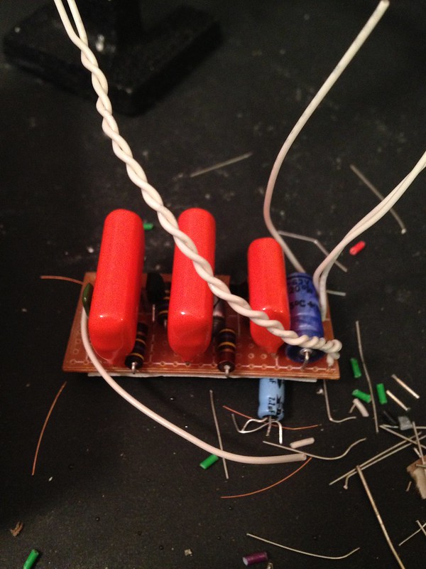
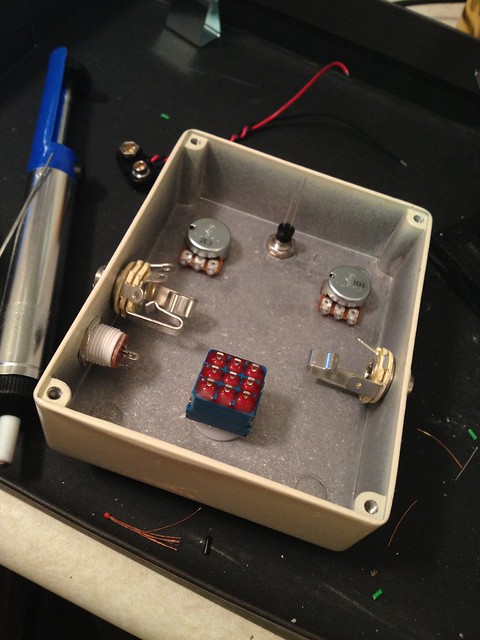
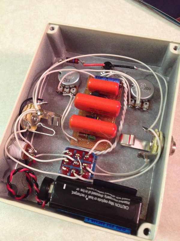
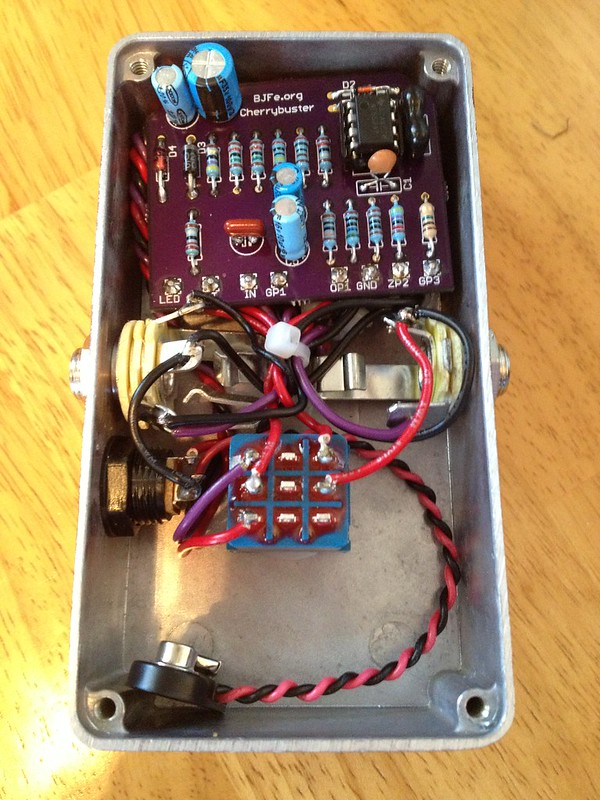
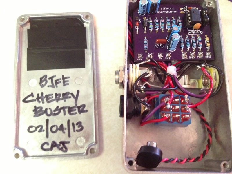
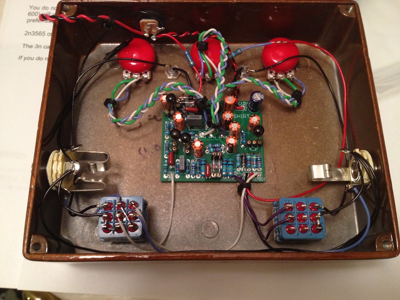
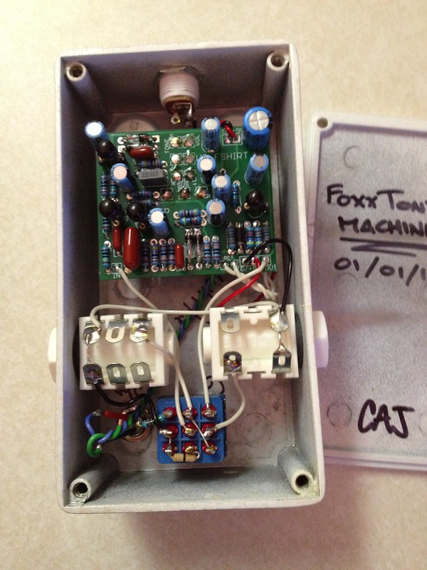
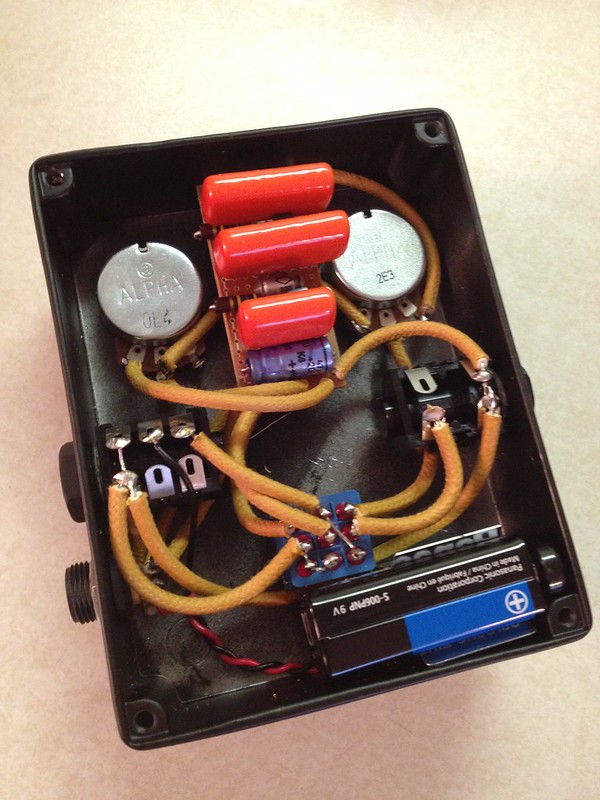
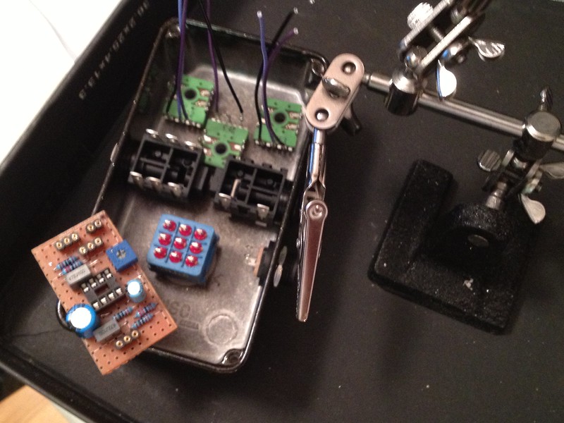
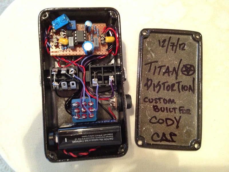
I'm pretty pleased with the guts on this one.  I say it every time but I hate working in small enclosures.  Despite that, I'm fortunately getting better at it.
#22
General Questions / Older sunking build doc
November 20, 2016, 12:54:14 PM
I have a sunking board from years ago now.  I searched and cannot find the appropriate build doc.  It is a square red PCB and doesn't appear to have a version number on it.  Can someone post, PM or point me to the build doc for this one, please?

Thanks!
#23


I finally got around to building this up this weekend.  I had some low gain Ge transistors lying around and figured "why not".  Well, I'm sure glad I did.  This thing is absolutely awesome!  I wasn't expecting much from the demos and was very pleasantly surprised.  I went with the Albini specs for the resistors and caps but decided to add my own diodes rather than using the unobtanium Ge ones.  It's not as wild as some of the HP demos I've heard but it sure as shit sounds awesome and very different from any distortion or fuzz I've heard.  Definitely going to go on my board.

Transistors - button 2N3565 (smallbear) and DSI OC81D (hfe ~50)
Diodes - Si BAT 46 and Ge 1N34A


Ugh, that solder iron burn on the input wire... smh.
#24
Build Reports / Super Fuzz Factory - Aion Flare PCB Build
November 10, 2016, 07:00:41 AM
So I liked my Fat Fuzz Factory so much I decided to see about the Aion Flare 8-knob fuzz factory.  And since that wasn't enough, I added the fat switch from the madbean Pudgii and a 3pdt toggle to swap the typical Si Q1 for a Ge one (AC127).  This one was built with a more traditional set of AC128s for Q2 and Q3 with hfe's of about 110 and 130.  It sounds pretty good although I'm on the fence about the usefulness of the body and soft controls.  The Tone control is a HUGE improvement on the effect though.  If I were to build a third one (dear god, I need to stop so hopefully I don't), I'd likely eliminate the Body control (input cap blend -- just use the standard input cap), fat switch (default to a larger cap between Q1 and Q2) and possibly try a lower gain Ge on the toggle.  The AC127 is about 130 hfe and sounds cool but a lower gain one would allow for more possible sounds since there's already plenty of gain on tap in this circuit.

Oh, and this it the first box I fully drilled myself.  It was a success for sure.  Top jacks, 8 knobs, 2 toggles, LED and footswitch in a 125B!


#25
Well, I have to say, this has been on the "to do" list for quite some time and I'm very please to finally have it finished.  This is seriously a must have pedal for fuzz fanatics and it's quite a simple build too.  I can't believe it's taken me so long to finally build one up for myself.  For transistors, I tried AC128's in standard hfe ranges (100 for Q2 and 130 for Q3) but found I preferred a higher gain set of AC188's (130 / 170).  The quirky "K" heat sink case also seemed fitting for a fuzz factory.  Anyway here it is...


I definitely think I'll be building a 7-knob fuzz factory soon with all the Joe Gagan recommended mods including socketing Q1 and trying some NPN germanium transistors there (or maybe having a Q1 Ge/Si switch... hm...).  That guy really has this circuit figured out.

Anyway, this one has left me really pleased.  The offboard wiring of the pots was a huge pain but the end result is quite neat and tidy.  I can usually work cleanly in large enclosures so this was a test.  One that I fortunately feel I passed  ;D

Man I love building fuzz pedals.
#26
So I am wiring up a tremshifter and the filter and trem rate pots in the existing schematic are wired such that the highest rates are full counter clockwise.  I would like that to be fully clockwise for my simple brain to more easily grasp the function of the controls.  The recommended wiring for these controls treats the pot like a variable resistor if I understand correctly (one wire to lug 1, the other two to lugs 2 and 3 as shown in the link below).  Both controls use an A1M pot.

http://effectslayouts.blogspot.com/2015/12/deadastronaut-tremshifter.html


So, if I want to reverse the sweep, I believe I can just modify the wiring to have the first wire connect to lug 3 (instead of 1) and the second wire connect to lugs 1 and 2 (instead of 2/3).  However, since it's an "A" log-taper pot, would i need to use a "C" reverse-log-taper pot as well to get similar performance?  I am thinking I would but am not sure and was hoping someone smarter than me could shed some light here.

Could anyone verify/clarify?  I know I could test one with my multimeter and plot the results but would rather know before ordering.  Thanks madbeaners.  ;)
#27
Tech Help - Projects Page / Moodring issues...
October 08, 2016, 02:38:23 PM
Got this wired up twice now.  Tried the buffered version and the LED always stayed lit.  So I unwired and tried the true bypass version.  I kept the extra wires from the switch and taped over them so they are not able to contact anything else.  For the "byp" wires, I twisted them, soldered and taped over them so I can undo it if I have to.

Anyway, I am getting a bypassed signal but no effect.  It's a bit of a mess at the point but photos are included below.


Voltage on IC1...

1 - 1.36
2 - 1.31
3 - 0.88
4 - 0
5 - 0.88
6 - 1.37
7 - 1.37
8 - 9.16

IC2 (regulator)
1 - 4.92
2 - 0
3 - 9.16

IC3
1 - 4.92
2 - 2.44
3 - 0
4 - 0
5 - 2.64
6 - 2.39
7 - 0.78
8 - 0.79
9 - 2.44
10 - 2.44
11 - 2.44
12 - 2.44
13 - 2.44
14 - 2.44
15 - 2.44
16 - 2.44

IC4
1 - 1.38
2 - 1.38
3 - 1.04
4 - 0
5 - 1.04
6 - 1.38
7 - 1.38
8 - 9.16

The PT2399 and regulator look fine.  The TL072's do not.  Anyone have any thoughts?

I almost forgot to add that I added a modulation board using the Grind Customs layout (on vero) as recommended in a modulated moodring build thread.  I used the layout below...


In addition, for replacements there...
-- Wired shape sw2 to shape sw3 (so no switch)
-- Removed 1k in parallel with LED and 2kB depth pot and 250kC for rate
-- Used On/On spdt for modulation switch and did not include ground (left open terminal) to just have an on/off style toggle

More info here... http://www.madbeanpedals.com/forum/index.php?topic=23642.0 ... on the modulation add-on

I hope this all makes sense...
#28
Build Reports / Labor Trade - Space Trash and Wormhole
October 04, 2016, 08:45:06 AM
Dan was kind enough to work with me on a couple builds.  I'll post each one as I complete them.

Over the weekend I finished the first "Space Trash" Casper Echobender pedal.  It looks and sounds great.  It can do standard delays, very long distorted delays, "noise generation" and even distortion (feedback maxed and delay time at minimum).  It's an interesting pedal for sure.


Just sent this guy back to Dan.  Next up is one of these for myself.  After that, the "Worm Hole" DeadAstronautFX Tremshifter.

#29
General Questions / Nope
September 18, 2016, 12:11:03 PM
Nevermind -- will post later with proper photos. 
#30
For standard center negative, which tab do I wire to ground and which gets the hot wire?  I am assuming the long tab is power and short is ground but want to confirm.

http://www.mammothelectronics.com/DC-Power-Jack-p/600-1004.htm

Thanks!
#31
General Questions / Sub-miniture light bulb
August 16, 2016, 06:04:36 AM
I bought these by accident instead of 3mm red LEDs.  I assume they will not function the same in a circuit since they mention on the site that the don't need CLRs.  Can anyone provide any insight on if these would be good for anything?  I purchased them because I was running low on red LED clipping diodes and didn't realize that these are something else entirely.

http://www.mammothelectronics.com/4SLED3MMRD-p/1000-100-rd.htm

Thanks!
#32
Looking for the build doc for the big dipper FX short stack and can't find it.  Built one of these a while ago and really liked it (and sold it).  Looking to build up another now for myself.

Thanks!
#33
Tech Help - Projects Page / Mood Ring - 10pf cap
August 10, 2016, 06:20:11 AM
OK -- this should hopefully be simple.  Can I sub something higher for this cap like a 33pf?  I'm building it not and have a socket in there so I will have the answer to this in the next few days.  In the meantime I wanted to ask to see if I should quickly try to pick up a 10pf to make sure I'm getting the right sound out of this thing.

For quick reference, here's a link to the build doc.  The cap is C2 right by the TL072 IC.
http://www.madbeanpedals.com/projects/Moodring/Moodring2015.pdf

Thanks!
#34
Not sure if this is cool to post here since it's not a madbean project.  Just let me know if this is inappropriate for this forum and I can remove it.

Anyway, I built a Sonic Titan over the weekend using this vero layout...
http://tagboardeffects.blogspot.com/2012/01/dam-sonic-titan.html

It's actually the second one I've built and I tweaked it slightly to add low end by changing out the 4u7 caps on the left side out for 10uF.  I also used a linear pot for gain as I liked that better.  My first (4 years ago that is now with a friend) was perfect as is.  This one is almost perfect.  The only issue is that when I turn the level pot up it increases volume and then the last 20% of the sweep (where I should have max output) the volume quickly drops and the signal cuts completely.  Anyone have an idea why this might be happening?  I feel like the answer should be straight forward since it seems to work perfectly otherwise.  I've already tried swapping out pots to no avail.

Here's the pedal...


Any help would be greatly appreciated.
#35
General Questions / Zero Point SDX Build ?'s
March 03, 2013, 12:10:56 AM
I am working on making this thing a reality -- quick first question.

For the SPDT and DPDT toggles... what "types" are they.

Looks to me like I need...

-- (2) SPDT "On-On" type
-- (1) DPDT "On-Off-On" type

Just wanted to confirm as there are on-off-on SPDT's and on-on-on DPDT's...  ???


Thanks!
#36
Build Reports / Silicon Fuzzrite
February 09, 2013, 08:32:36 AM
Built up another one of these -- this one in white.

Orange drop caps, carbon comp resistors, KSP42 and 2n4401 transistors.  Sounds killer.

Populated board


Beginning of the enclosure


Boxed up


Tested (success!)


And done  :D
#37
At long last, my Cherry Buster is finally complete -- although I put the wrong date inside   ::)

It's an always on buster with variable input and output impedance along with a boost.  The controls, left to right, are input Z, boost (bigger knob), output Z.  It was a group project on the BJFe forums that I helped set up along with help from Bjorn on the circuit design, Donner on enclosures and a friend, Bill, on board layout. I sourced boards and parts for "kits" for several folks and did the build docs.  If anyone might be interested in boards I have a few extras (I need to ship a few more out to folks who expressed interest way back when that I just now realized I never shipped  ??? yikes) and I can post the build docs.  I will post something in the FS forum soon when I figure out how many I have left.

Anyway, it was definitely a lot to fit in one box but I'm really happy with how it all worked out.  Pretty clean although it could probably be cleaner -- I'm used to having more space to work with.  Anyway, here it is in all its glory.  Gonna get a spot at the front of the chain if/when I ever wire up my board


Boost off (RED)


Boost on (BLUE)

#38
Build Reports / Madbean Wolf Shirt (Foxx Tone Machine)
January 02, 2013, 01:30:20 PM
I built one of these a while ago for a friend (back in Sept '12) -- as requested I used a giant enclosure  ;D


I loved it so much I've been planning on making one for myself... And on the first day of the new year I finally did it.  Done up in all white  :D


Octave on/off on the toggle and the LED changes from green (w/ octave) to blue (w/o octave) depending on switch setting.
#39
I had a little fun this weekend -- built myself a few pedals.

Silicon Fuzzrite with mojo components...


Tweaked D*A*M Sonic Titan built for a friend...


And finally, with the help of the folks in the tech area I got this up and running... can't believe it was a diode with the wrong orientation causing the crazy behavior.  LOVE it now.  Man everyone should own a fuzz factory.  They're soo incredibly versatile and fun to tweak!


(before I got the LED wired)


I've been having a great time building this weekend.  Very happy with these new projects and wil be building at least one or two more of each for folks.  Also have an autowah and trem on the horizon.  My goal is to eventually build most of the effects I use and stop buying stuff.  With the wealth of information folks like you guys put out there, I don't think I'll be running out of projects any time soon.
#40
Tech Help - Projects Page / Ever get a bad 9v socket?
December 09, 2012, 01:47:30 PM
I've had two builds now with issues with the 9v socket.  The most recent one is wired up per the standard madbean wiring diagram (http://www.madbeanpedals.com/tutorials/downloads/StandardWiring_MBP.pdf) with a battery.  One lug goes to ground, one goes to the positive terminal of the battery and the last lug goes to the positive terminal of the LED and the 9v in for the board.  When I don't have a plug in the 9v socket the battery works great and the effect and LED work flawlessly.  The second I plug in power (either my PP2+ or a one spot... tried both), the effect dies and the LED goes out.  Seems like since all of the lugs/wires/connections are used to power the effect with the battery it can't be an issue with those, right?  So is this a bad jack?  It's the second effect that has given me issues with the power jack and I'm starting to wonder if they are from a bad batch or something...?