News:

Forum may be experiencing issues.

Main Menu
Menu

Show posts

This section allows you to view all posts made by this member. Note that you can only see posts made in areas you currently have access to.

Show posts Menu

Messages - cajone5

#61
Tech Help - Projects Page / Re: Aion Refractor Issues...
December 18, 2017, 02:11:06 PM
If it works they make it easier...

If they doesn't, it blocks the solder side of the board :)
#62
Tech Help - Projects Page / Re: Aion Refractor Issues...
December 18, 2017, 12:16:53 PM
I'll pull it apart and reflow/check for any shorts anywhere tonight.  Although those damn board mounted pots will make it a pain, hopefully it won't be too bad.  Will update once I have a chance to do that.

Thanks for the review!
#63
I need this too... thought I had it as well and checked and I don't.  Still have to build this one up.
#64
Tech Help - Projects Page / Re: Aion Refractor Issues...
December 18, 2017, 05:23:18 AM
Quote from: EBK on December 17, 2017, 06:13:21 PM
Tantalum cap polarity?

I didn't check that before but I did now.  Looks like that one's correct to me as well... hmm :-\
#65
Another swing and a miss.  I built this Klon clone (hopefully my last) and it's gated and has issues in bypass as well as on so my issue is likely around IC1, I think but not sure.  Anyway, I already verified all components and polarities although I could have made a mistake somewhere.  Voltages are off.  Even swapped IC's to no avail.  Will pull the board and reflow if I can't get any leads on the issue... My TL072 voltages look way off.

Substitutions:

C6 - 390n -- used a 330n and 56n in parallel
R12 - 422k -- used 470k and 3.9M in parallel


POWER: 9.5V
Diode voltages (cathode/anode)

Zener Voltage: 0 / 9.5V
D3 (1n4002): 13.59V / 9.5V
D4 (1n4002): 17.31V / 13.59V

IC 1: TLO72CP
Pin 1, 1.334
Pin 2, 1.334
Pin 3, 0.962
Pin 4, 0
Pin 5, 0.665
Pin 6, 1.083
Pin 7, 8.77
Pin 8, 9.50

IC 2: TLO72CP
Pin 1, -2.730
Pin 2, 0.472
Pin 3, 0.472
Pin 4, -9.14
Pin 5, 0.473
Pin 6, 0.471
Pin 7, 3.695
Pin 8, 17.31

IC 3: TC1044
Pin 1, 9.5
Pin 2, 4.918
Pin 3, 0
Pin 4, -4.424
Pin 5, -9.14
Pin 6, 4.651
Pin 7, 6.184
Pin 8, 9.5
#66
Other than travel (I live across the country from most of my family), the only hard part for me is the adult family gift giving.  I am 32 and I wish my parents would quit giving gifts because it creates the obligation to reciprocate and frankly none of us need anything in the price range that these gifts live (that we can't just get ourselves).  So we are fortunate to not want but still, it feels empty and silly to me.  Half the time it's just trading forms of money (cash, gift cards, gift certificates, etc.) and it's tiring.  It also creates extra stress leading up to the holiday trying to find something for everyone.  I'd prefer everyone save their money and the headache of attempting to shop for each other and just focused on spending time together and, if anything, sharing an experience, instead of buying gifts.

And honestly, the above isn't a very big deal.  It's just something I always struggle with.  Sometimes I feel like a grinch for it but ultimately, I just dislike the consumerism, the collecting "stuff" and the emptiness of the excessive gift giving.
#67
Open Discussion / Re: You think Guitar Center goes under?
December 13, 2017, 07:53:05 AM
I haven't been very enticed by either the selection or pricing in my local GC's.  My purchases have all been online and after extensive research.  Also, I'm not seeing myself buying up a collection of guitars and amps.  Just a couple good choices so I feel like all I'm set for is little purchases (pedals, cables, picks, strings, etc.) and if I'm going to make a major purchase it will probably be on the used market where there's a glut of choices and much better deals to be had.
#68
Tech Help - Projects Page / Re: Cascadia Issues
December 12, 2017, 05:01:50 AM
They were from Adafruit: https://www.adafruit.com/

I ordered something from them a few months ago because it was the only site with it in stock (either a vactrol or an odd IC) and grabbed some toggles as well. They have a blue body so they stand out among my red ones. Haven't really used them until now. Although I think the problem may be my new solder. It seems to take quite a bit more heat to get it to flow and take to things; particularly jacks and switches. I think I must have melted the switch guts soldering them in the first time.

DPDT: https://www.adafruit.com/product/3220

SPDT: https://www.adafruit.com/product/3221

They're probably fine and it was user error but I won't be seeking these out again. :)
#69
Tech Help - Projects Page / Re: Cascadia Issues
December 11, 2017, 06:22:10 PM
Replaced the 3k3's and it sounded much better.

DPDT Switch was still not working right so I unsoldered it with quite a bit of effort and replaced it.

DPDT switch works.

SPDT stopped working...

Replaced that...

FINALLY everything is working and it sounds outstanding.  I'm amazed at the versatility of this thing.  Feels like it's going to be my #1 dirt pedal moving forward.

Thanks everyone for all your help!
#70
Tech Help - Projects Page / Re: Cascadia Issues
December 11, 2017, 04:33:32 PM
SMH... disecting the thing to replace those.

My 10k's are below my 3.3k's in my box... all I can think is that I grabbed the wrong ones somehow by mistake.  Jeeeeeeze...
#71
Tech Help - Projects Page / Re: Cascadia Issues
December 11, 2017, 01:12:44 PM
Checked 10R resistors...

R7, R10, R15, R22, R30, R33, R41, R49, R51 all measure 10.2 - 10.5R

For the transistors, I think Q9 is nearest the tone stack but here are all the voltages on all legs with treble at minimum, around middle and maxed... Spoiler alert, no change in any reading regardless of treble setting...

             Min | Mid | Max (Treble pot setting)
Q2 C - 9.40 | 9.40 | 9.40
Q2 B - 3.68 | 3.68 | 3.68
Q2 E - 3.06 | 3.06 | 3.06

Q4 C - 9.42 | 9.42 | 9.42
Q4 B - 4.19 | 4.19 | 4.19
Q4 E - 3.60 | 3.60 | 3.60

Q6 C - 9.42 | 9.42 | 9.42
Q6 B - 2.74 | 2.74 | 2.74
Q6 E - 2.16 | 2.16 | 2.16

Q9 C - 9.42 | 9.42 | 9.42
Q9 B - 1.16 | 1.16 | 1.16
Q9 E - 0.55 | 0.55 | 0.55

Q11 C - 9.42 | 9.42 | 9.42
Q11 B - 0.90 | 0.90 | 0.90
Q11 E - 0.37 | 0.37 | 0.37
#72
Tech Help - Projects Page / Re: Cascadia Issues
December 08, 2017, 05:43:39 PM
Yes forward voltage around 0.3v for the smallbear 1n695s

For the transistors -- voltages on middle leg...

Power: 9.5v

Q2 - 3.675
Q4 - 4.222
Q6 - 2.775
Q9 - 1.155
Q11 - 0.901
#73
Tech Help - Projects Page / Re: Cascadia Issues
December 08, 2017, 05:00:40 PM
Backwards treble control would have to be an issue with C20/C22/C24/C25 -- without removing them they appear right... it's odd.

The switch could be an issue with C20 or C21 I'd guess but they look good too... I'm lost.  I'm not sure I'll get back to this until next week.  Heading out for a wedding tomorrow morning.  Oh well, hopefully I can sort it out when I get back.
#74
Tech Help - Projects Page / Re: Cascadia Issues
December 08, 2017, 04:27:09 PM
Shoot -- just checked continuity and I'm getting continuity across one of the 100uf electros... swapping now...

Swapped and voltage is now abou -8.9v on pin 5 so that problem is fixed.

-- Bright switch still doesn't work when flipped to the right although if I crank every knob I get a faint well-below-unity clean tone coming out... guessing I have something in there that's the wrong value but unclear where to start looking

-- Treble control still works backwards which makes no sense to me unless I have a ottally wrong value somewhere (again).

Overall, it still sounds flubby and somewhat gated and that probably indicates an error in the tone control as I am guessing I've screwed something up and choked the high end?

Thanks for the great help so far!
#75
Tech Help - Projects Page / Re: Cascadia Issues
December 08, 2017, 04:25:01 PM
Quote from: jubal81 on December 08, 2017, 01:28:04 PM
Thanks for posting voltages.

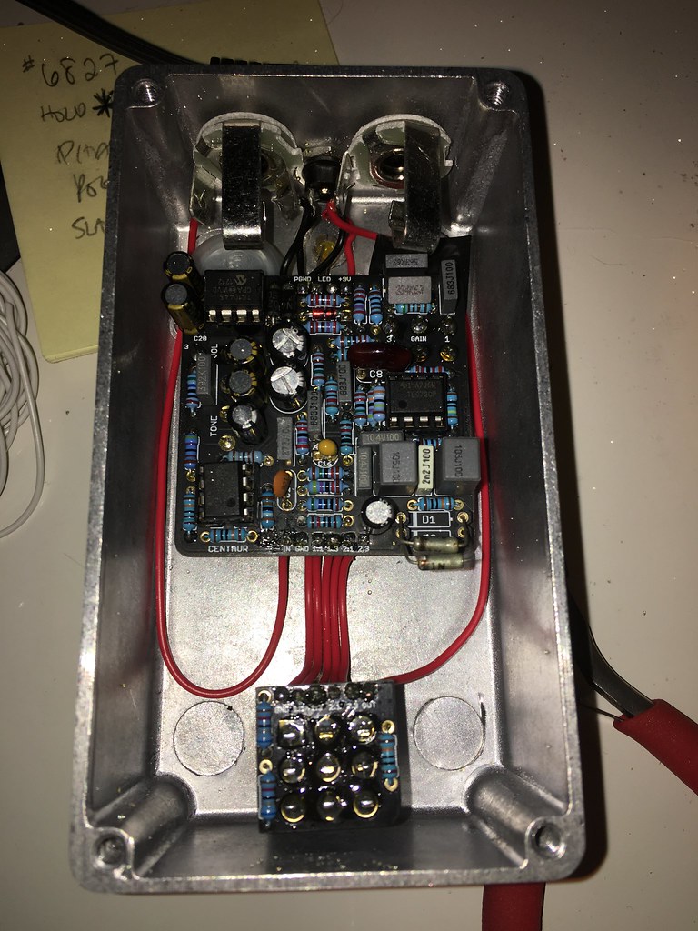
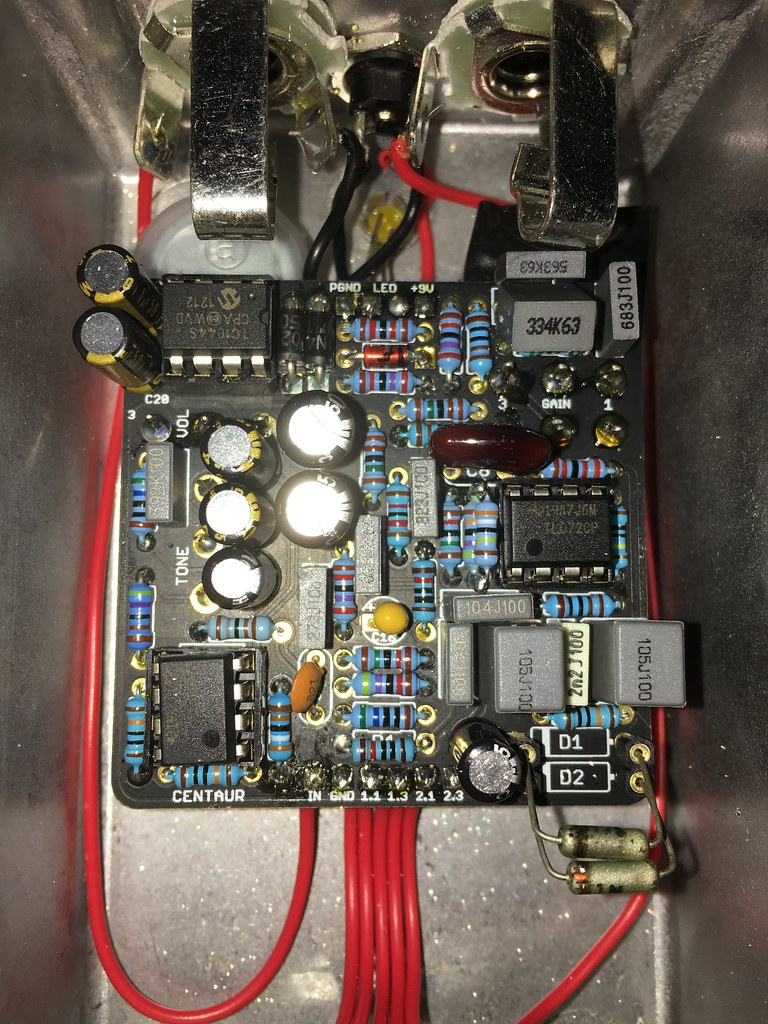
Pin 5 is the negative output, which should be more like -8.6v or something in that territory. Your electro caps look like they're oriented correctly, but I can't see the ones on the footswitch board.

Nothing else is jumping out.

I'd recommend double checking the orientation on the charge pump chip and the electro caps on the footswitch PCB and taking another look at solder joints. Also, check for shorts across the 100uf caps on the footswitch board.

Charge pump and electros are oriented as shown in the build doc photos.

Pin 5 is still the same after reflowing everything on the footswitch PCB.  Here's a pic of the other side of that PCB...


I did check the strip at the top and get about -9v on the third from the right and +9.4v or so on the fourth, about 0.128v on 7 and 8 and the rest are zero.

Does that help?

Quote from: jubal81 on December 08, 2017, 01:33:47 PM
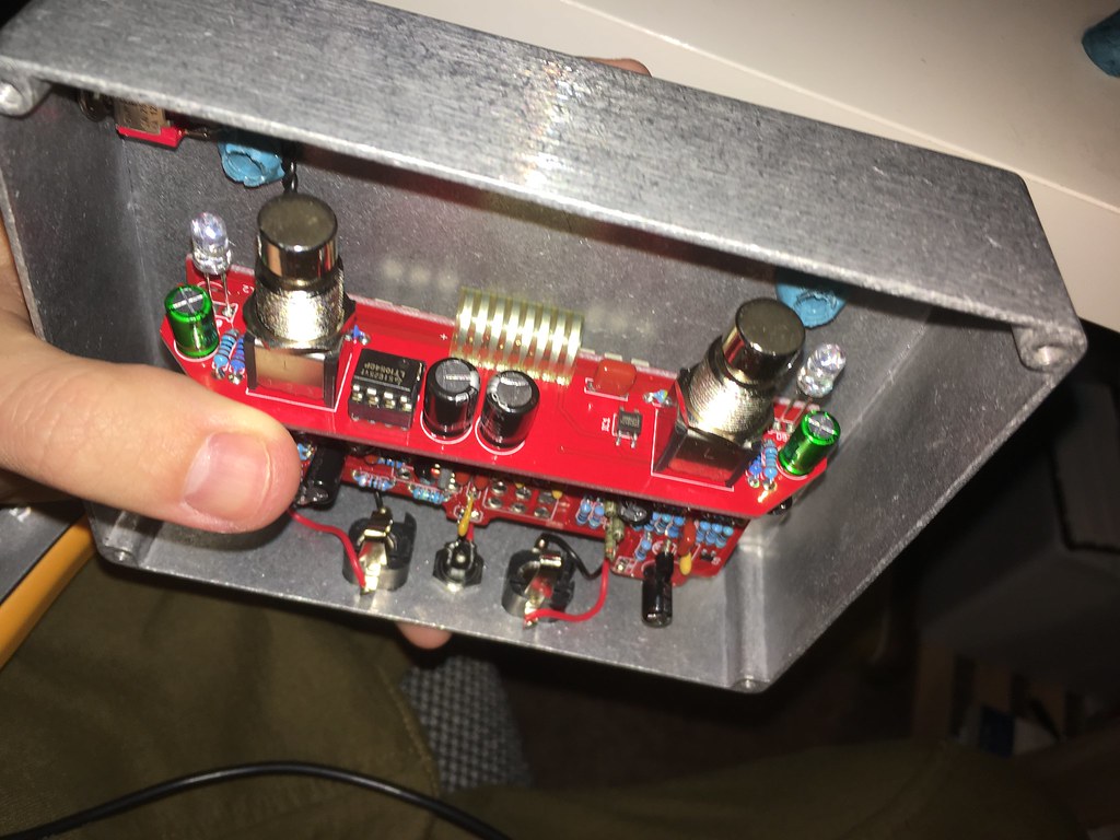
Also, R5 is the resistor in the far bottom left of the pic (horizontal). Wiring could connect there, but looks like it goes straight up from the switch to possibly the wrong resistor?

Yep bottom right in the long row.  It just looks odd because I have the wire run up and over to look a bit cleaner.  I checked across R5 and with the switch in each position I have about...

450 ohm
2.4k ohm
1k ohm

That's what I was shooting for with my values (1.8k and 560 in parallel if I recall) so that "mod" seems to check out.