
...and they also carry Monkeyman Guitar straps along with the huge selection of strings and picks.
- Welcome to madbeanpedals::forum.
This section allows you to view all posts made by this member. Note that you can only see posts made in areas you currently have access to.
#2177
General Questions / Re: Your boxing technique
April 03, 2013, 07:01:13 PM
I use 1/16" plywood because i have it but in a pinch a piece of box board like from a cereal box would be fine.
dave
dave
#2178
General Questions / Re: Your boxing technique
April 03, 2013, 04:10:51 PM
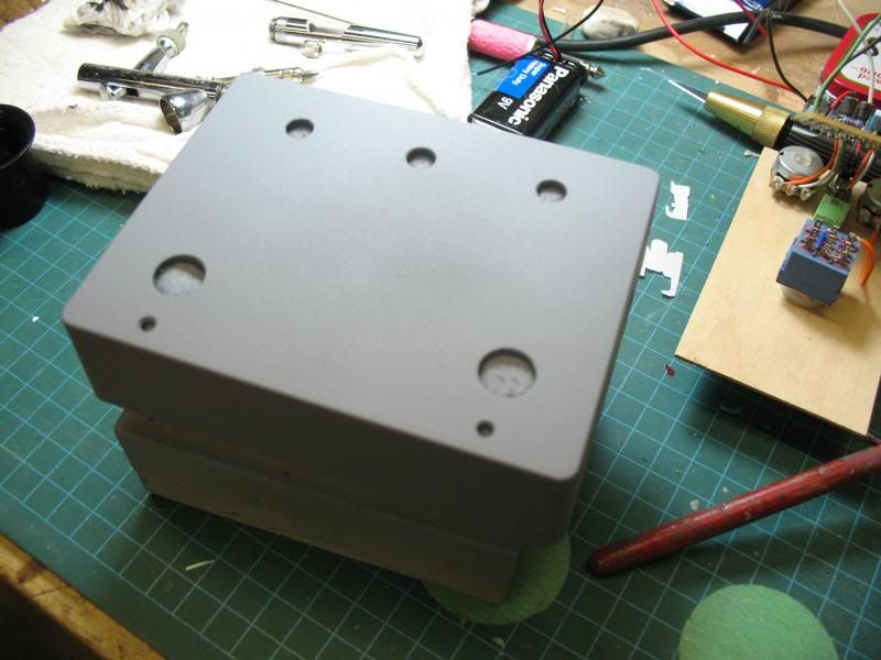
I make a jig based on the drill template of the enclosure, mount all the pots, switches and board to that, wire all that up. Install the wires to the board that will be going to the jacks and then it's ready to install in the finished enclosure. Easy to trim the flying leads and attach to their jacks and wire from jacks to stompswitch after things are in the enclosure.
dave
dave
#2179
Build Reports / Re: Another Cosmo
April 03, 2013, 12:15:51 AM
Great idea and great execution! Love the shade of green, what's the paint that you used to give you the textured finish?
If you're going to be making many more of these or building tube amps you can get a step bit that goes to 1 3/8", makes short work of hole creation.
Very nicely done!
dave
If you're going to be making many more of these or building tube amps you can get a step bit that goes to 1 3/8", makes short work of hole creation.
Very nicely done!
dave
#2180
Build Reports / Re: From Firebomb to improvised explosive deVice
April 01, 2013, 02:30:28 AM
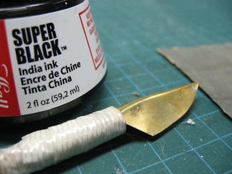
Hi Bill, The wire is a Teflon/Kapton insulated coax i picked up on ebay, very stiff and can only get away with a gradual curve, no 90° bends, very small diameter package. Put 1/8" Techflex over it. Really like the teflon, no worries of creating a short when soldering to shield. To attach a wire to the shield all you need to do is strip of the insulation, wrap a piece of wire around the shield, trim off the excess shield then solder the two together, cover with heatshrink.
He also has longer lengths available.
http://www.ebay.ca/itm/10-feet-26-AWG-Shielded-Silver-Kapton-Teflon-Wire-Coax-/230824758424?pt=US_Audio_Cables_Adapters&hash=item35be3a4c98#ht_500wt_1203
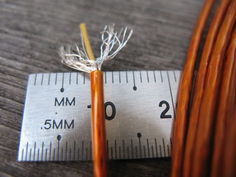
This one was soldered before trimming off excess shield, try it both ways, never created a short with this wire.
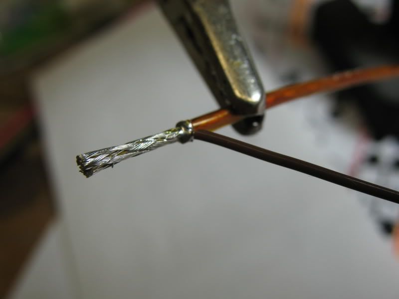
dave
He also has longer lengths available.
http://www.ebay.ca/itm/10-feet-26-AWG-Shielded-Silver-Kapton-Teflon-Wire-Coax-/230824758424?pt=US_Audio_Cables_Adapters&hash=item35be3a4c98#ht_500wt_1203
This one was soldered before trimming off excess shield, try it both ways, never created a short with this wire.
dave
#2181
Open Discussion / Re: Finally etched my own pcbs....
March 31, 2013, 03:14:45 PM
MG Chemicals makes a product called Liquid Tin that's easy to get over hear and easy to use but i find a quick spray with lacquer looks and works better, (after you buff up the copper nice.) The touch of the soldering iron vaporizes the lacquer on the pad when you solder to it.
dave
A tip on holes/pads, when you start making your own layouts use pads with very small holes, i use 20mil no matter the size of the pad or the size of the needed drilled hole. When you go to drill, the tiny center etch of the pad acts as a center punched hole and the drill easily finds the center of the pad, self-centers the drill. If i'm using someone elses art i'll use Inkscape to lay in my new pads over the orignal pads so they meet my preferences.
#2182
Open Discussion / Re: Re: Finally etched my own pcbs....
March 30, 2013, 06:04:07 PMQuote from: ch1naski on March 30, 2013, 02:27:07 PM
Now if I could just find a way to print out that tremulous lune pcb PDF from tonepad.... the security on the download doesn't allow printing or copying any of the doc. So I can't scale it to do the toner transfer.
I thought it was supposed to be free to use? Hmmmm.
So I guess my next move would be to design my own board. I don't feel right doing in-production boards, those need to be supported by buying them. Some of the guys around here and their self-designed boards are inspirational.
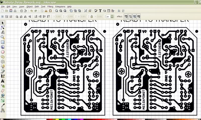
You can use Inkscape to modify Tonepad documents. Open up Inkscape find and open the Tonepad pdf doc with Inkscape, save the document as an .svg file and you can have your way with the whole document. I've redrawn their boards to accomodate components i wanted to use, moved traces around, relabeled, with Inkscape you can do anything you want to the Tonepad documents. (Not so with Madbean's but there are other's pdf's that can be manipulated with Inkscape.)
I am puzzled by the scaling issue you're having, as long as you set your printer to print the pdf at 100%, it should printout the correct size.
Reworked Rebote 2.5 doc. Original colour coded layout is on the left, redraw right.
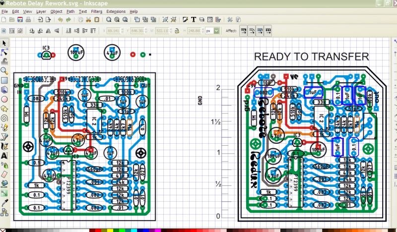
Redrawn pcb art.
dave
#2183
Build Reports / Re: From Firebomb to improvised explosive deVice
March 30, 2013, 12:25:07 AM
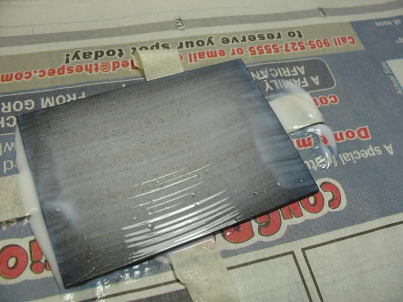
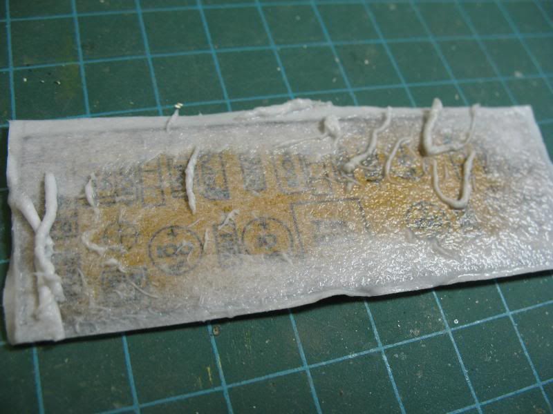
George is right it's toner transfer, but i use acrylic medium and not heat to accomplish the transfer, same thing i do to transfer to the enclosure, no more decal.
The tough part was figuring out a way to register the silkscreen art to pcb.
Story so far...
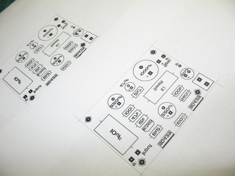
Design a pcb layout in ExpressPCB. Etch a board.
When i do the final sizing/shaping of the etched pcb i get it as close as i can to the border that surrounds the layout, don't want to obliterate the border just touch it
From ExpressPCB open up the Print Box and select Silkscreen layer (component outline), also for printer select pdf printer=> print. I've got Bullzip PDF Printer, freeware, no complaints.
Open the silkscreen pdf in Inkscape then save as an .svg file. I don't like the ExpressPCB font so i relabel the components and add any other legending that's needed using more interesting fonts.
So far you have a silkscreen border that matches perfectly with the etched border on the back of the pcb but no way to see whether they're aligned when you do the transfer.
The simple trick that seems to be working well so far is to draw a new border around the silkscreen leaving a small equadistant gap between the old and new borders. A this point i'll make a copy so i have two images, group one of them set it aside. The second one you delete the original silkscreen, unless you want it to transfer to the pcb, group the new art, mirror the art and (laser) print to regular cheap paper. Photocopy would work too, long as you have toner artwork.)
You now have your silkscreen art and an etched/sized pcb that will lay within the border of the silkscreen art. Because you sized the pcb perfectly, well close, when you lay it on your art you can trust your eye to see that the white gap between the pcb and the art is equadistant and therefore everything is going to line up aces.
I paint the pcb with acrylics and use an acrylic medium called GAC200 (by Golden) for the transfer. Spread a good coat of medium on the top of the pcb board, lay it aligned onto you artwork, there's not much wiggle time here, they grab well. I'll secure the board to paper with a bit of masking tape, flip it over and run a brayer over the paper to squeeze out the excess medium and ensure good contact. Not too hard because the wet paper will stretch over the edges of the board and you might get some minor distorting of the art.
Let it dry, rewet the paper and rub the papre off with your fingers. Never going to get all the papre off in one go so let it dry again, rewet and rub, takes a few goes but it will come off.
I've found it much easier to do all this messing about and then drill the holes. Always drilled the holes first and then with all the paint and medium had to go back and redo them all, live and learn.
Only pictures i have are from the initial efforts with the method, a fail but gives you an idea of the toner transfer bit. Sanded this one off and did it again with better results
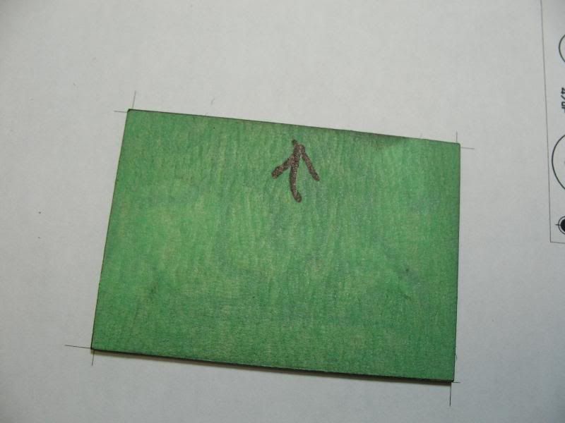
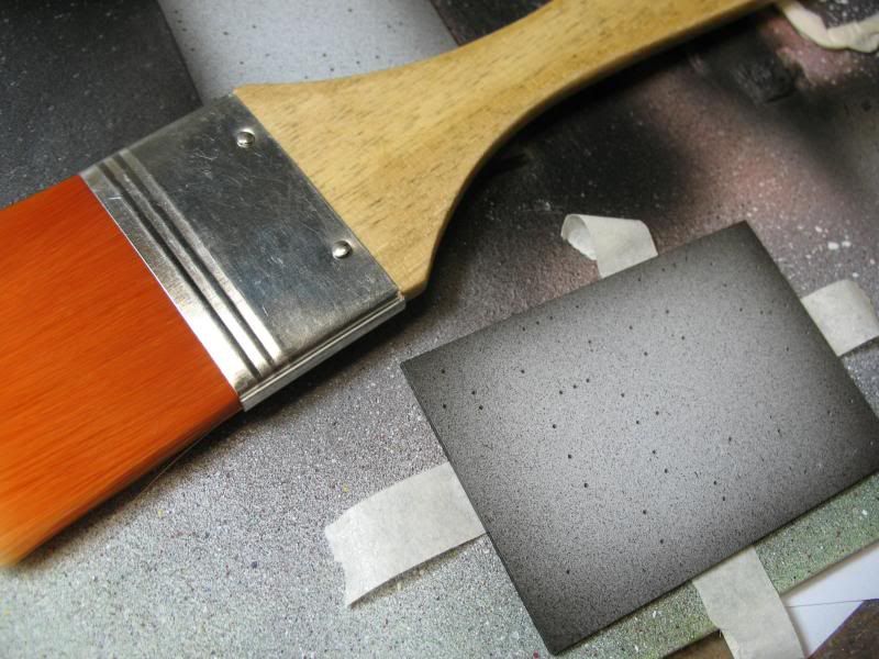
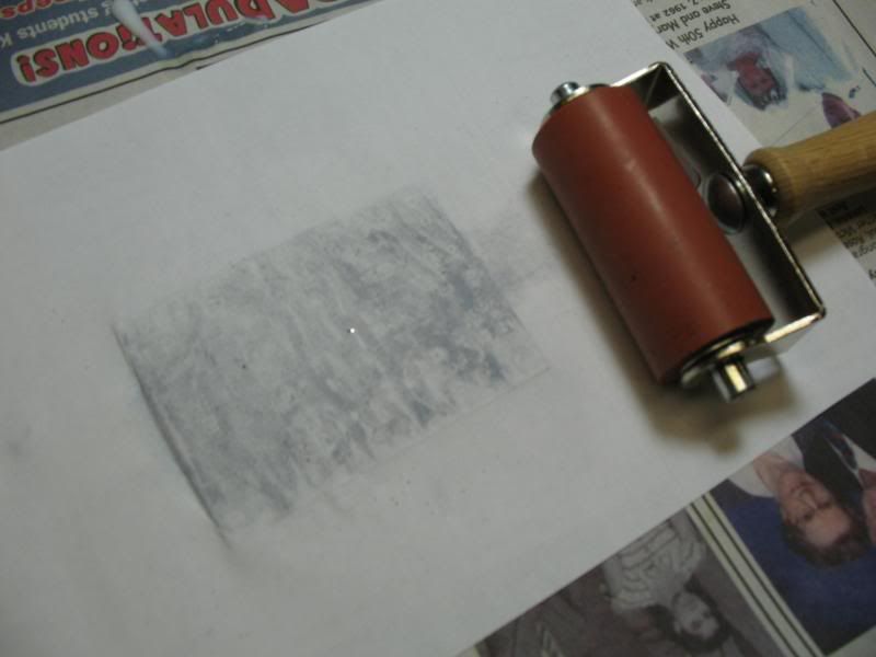
Better... but still a ways to go.
dave
The tough part was figuring out a way to register the silkscreen art to pcb.
Story so far...
Design a pcb layout in ExpressPCB. Etch a board.
When i do the final sizing/shaping of the etched pcb i get it as close as i can to the border that surrounds the layout, don't want to obliterate the border just touch it
From ExpressPCB open up the Print Box and select Silkscreen layer (component outline), also for printer select pdf printer=> print. I've got Bullzip PDF Printer, freeware, no complaints.
Open the silkscreen pdf in Inkscape then save as an .svg file. I don't like the ExpressPCB font so i relabel the components and add any other legending that's needed using more interesting fonts.
So far you have a silkscreen border that matches perfectly with the etched border on the back of the pcb but no way to see whether they're aligned when you do the transfer.
The simple trick that seems to be working well so far is to draw a new border around the silkscreen leaving a small equadistant gap between the old and new borders. A this point i'll make a copy so i have two images, group one of them set it aside. The second one you delete the original silkscreen, unless you want it to transfer to the pcb, group the new art, mirror the art and (laser) print to regular cheap paper. Photocopy would work too, long as you have toner artwork.)
You now have your silkscreen art and an etched/sized pcb that will lay within the border of the silkscreen art. Because you sized the pcb perfectly, well close, when you lay it on your art you can trust your eye to see that the white gap between the pcb and the art is equadistant and therefore everything is going to line up aces.
I paint the pcb with acrylics and use an acrylic medium called GAC200 (by Golden) for the transfer. Spread a good coat of medium on the top of the pcb board, lay it aligned onto you artwork, there's not much wiggle time here, they grab well. I'll secure the board to paper with a bit of masking tape, flip it over and run a brayer over the paper to squeeze out the excess medium and ensure good contact. Not too hard because the wet paper will stretch over the edges of the board and you might get some minor distorting of the art.
Let it dry, rewet the paper and rub the papre off with your fingers. Never going to get all the papre off in one go so let it dry again, rewet and rub, takes a few goes but it will come off.
I've found it much easier to do all this messing about and then drill the holes. Always drilled the holes first and then with all the paint and medium had to go back and redo them all, live and learn.
Only pictures i have are from the initial efforts with the method, a fail but gives you an idea of the toner transfer bit. Sanded this one off and did it again with better results
Better... but still a ways to go.
dave
#2184
Build Reports / Re: From Firebomb to improvised explosive deVice
March 29, 2013, 05:57:33 PM
Thank you everyone! You made me blush.
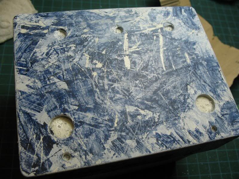
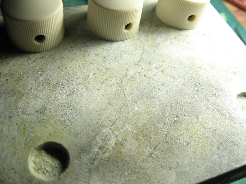
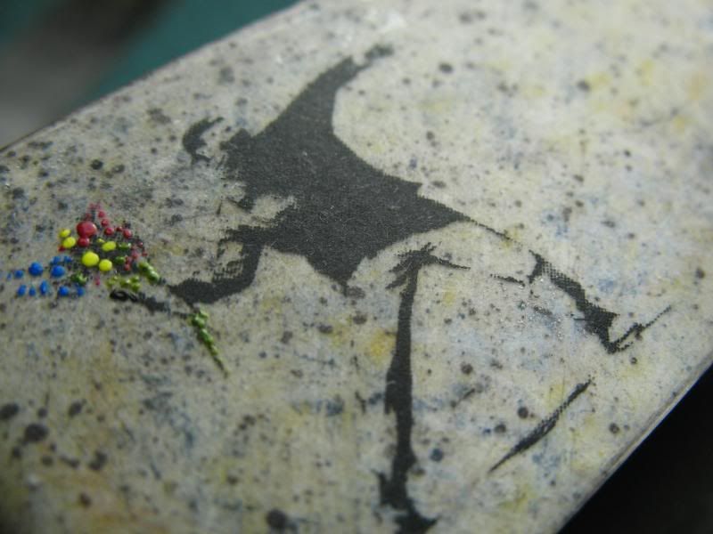
As to how the background is done, it's pretty haphazard. I wanted an old, worn looking base like the concrete floor of my basement (that helps limit colour choices). Put some paint on, maybe wipe or rinse some off while still wet... let it dry, sand more off, scrape some off just chew it up. Add more paint, same colour or different, mess it up some more. Repeat...
Anytime i get a layer i want to preserve i airbrush on a coat or two of GAC200/Airbrush Medium (GAC200 is too viscose to spray as is) before moving on to the next painting/abuse. The GAC200 dries surprisingly hard and does a great job of protecting the underpainting from the next round of abuse. GAC200 is also the medium i use for doing toner transfers.
It's all about putting paint on and taking lots off. Sometimes put on with a paint brush, airbrush, dip pens, toothpicks, pallet knives, splattered with toothbrushes/scrub brushes, shot from a syringe, pushed around with compressed air, just grab whatever is handy on the workbench and put it to use applying or taking the paint off. Playtime in the paint box, anything goes. Scrub with alcohol, throw rock salt onto a very wet thin coat of paint and let that dry before brushing the salt off. Play, play, play... never really know where it's going to go, what i envision when i start and where it all ends up are usually worlds apart.
If there's specific info you're after let me know and i'll do my best to try and fill in the holes!
Take care!
dave
#2185
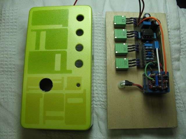
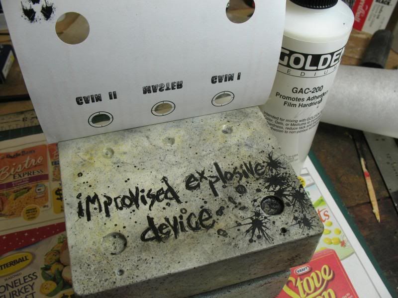
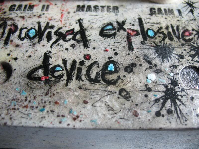
Build Reports / From Firebomb to improvised explosive deVice
March 27, 2013, 11:34:50 PM
Hello All,
How do you make a SHO even better...
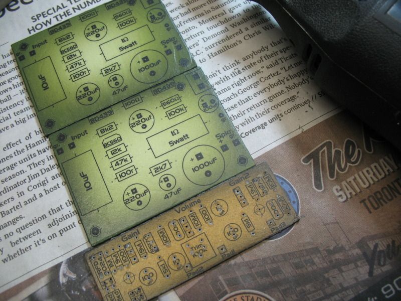
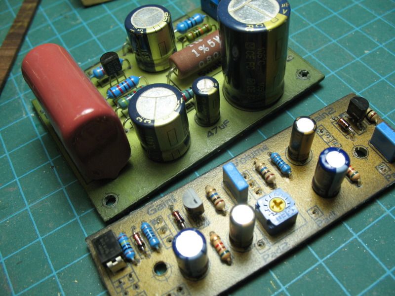
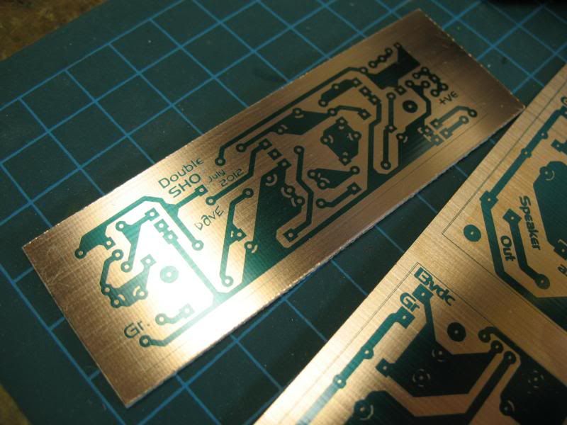
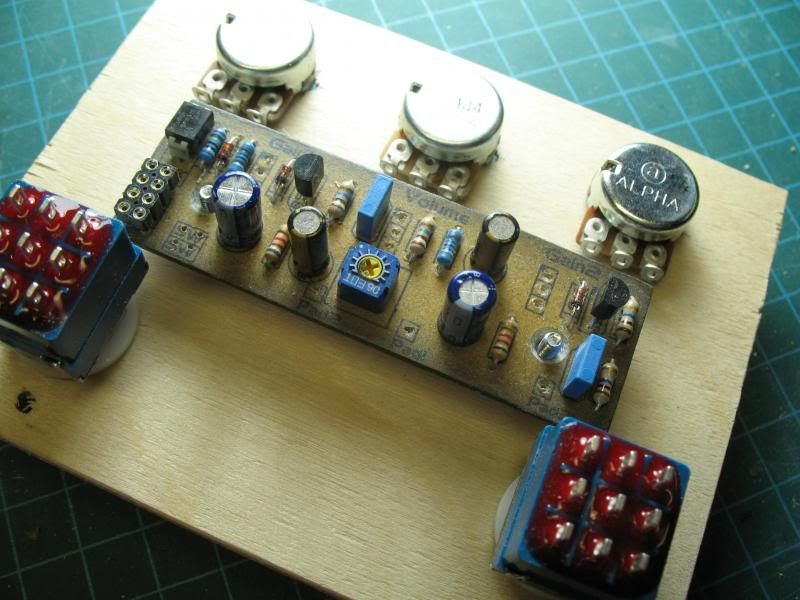
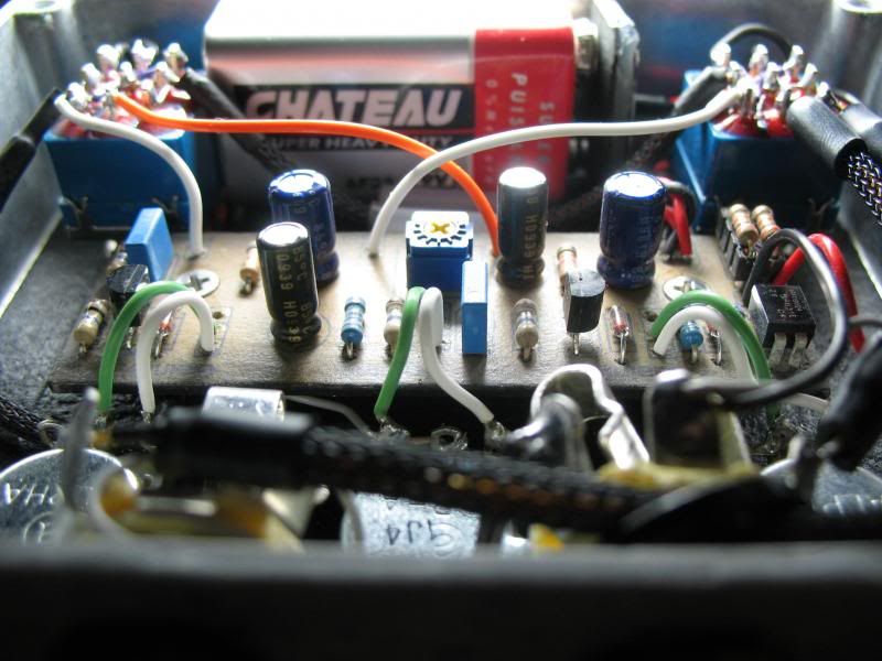
... make a Firebomb. To the Firebomb circuit added a Geofex polarity protection scheme that uses an IRFD9024 MOSFET, added a second/parallel 100Ω/100µF filter so each SHO has it's own PS filter and added a trimmer after the first boost to trim it back if deemed necessary. Used ExpressPCB to do the layout and then Inkscape to dress things up and create a pseudo silkscreen. PCB painted with acrylics to disguise the puky natural colour. Am getting away with 30K resistors for current limiting on the LED's so with everything running i'm looking at only ~2ma.
Shielded cable was used for the long runs between jacks and switches... needed?
http://www.madbeanpedals.com/projects/Firebomb/docs/Firebomb.pdf
http://www.geofex.com/article_folders/mosswitch/mosswitch.htm
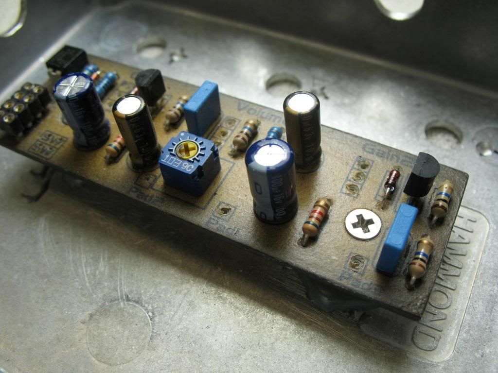
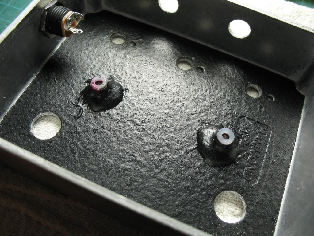
Assembly jig used to do all wiring except to the jacks. Do the jacks once the assembled components are mounted in the enclosure.
For painting the enclosure i first use a self-etching primer then over that coat with BIN Primer Sealer Stain-Killer, nice high solids, sands well and is white.
After that, acrylic paints and mediums, India Ink, toner transfers, flakes of rust, paint and dirt. Applied stuff with whatever's handy, paintbrushes, airbrushes, fingers, dip pens and pallet knives/spatulas. Lots of paint removal in the finishing process, water while paints are wet, sandpaper, files and rifflers, dental picks etc. The play/experiments... to be continued...
Clearcoat is airbrushed Target 7000 waterborne lacquer.
I.R.D., improvised 'riting device, pop-can-pen.
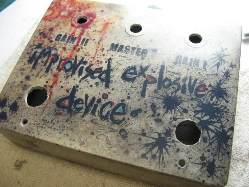
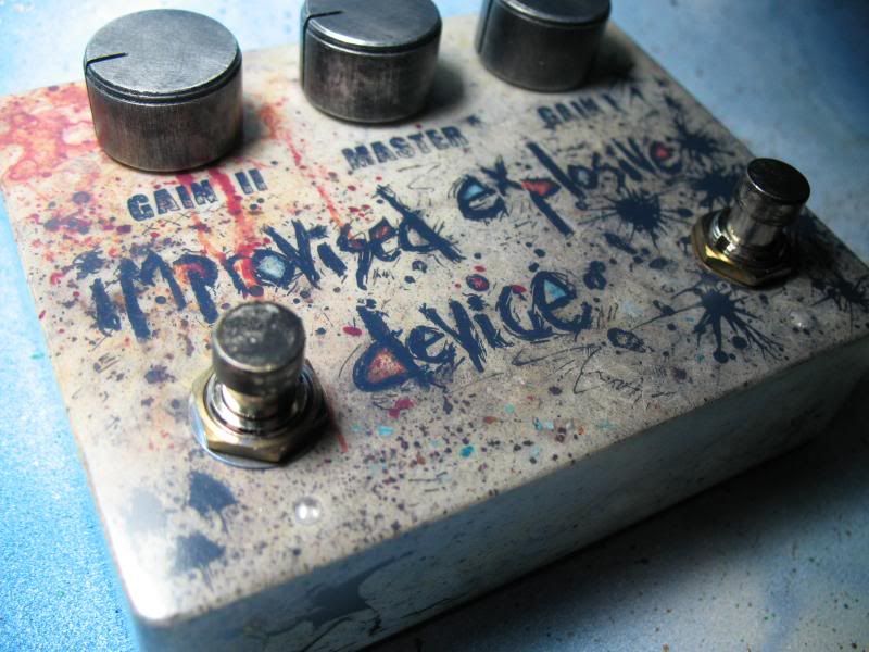 See ya'
dave
How do you make a SHO even better...
... make a Firebomb. To the Firebomb circuit added a Geofex polarity protection scheme that uses an IRFD9024 MOSFET, added a second/parallel 100Ω/100µF filter so each SHO has it's own PS filter and added a trimmer after the first boost to trim it back if deemed necessary. Used ExpressPCB to do the layout and then Inkscape to dress things up and create a pseudo silkscreen. PCB painted with acrylics to disguise the puky natural colour. Am getting away with 30K resistors for current limiting on the LED's so with everything running i'm looking at only ~2ma.
Shielded cable was used for the long runs between jacks and switches... needed?
http://www.madbeanpedals.com/projects/Firebomb/docs/Firebomb.pdf
http://www.geofex.com/article_folders/mosswitch/mosswitch.htm
Assembly jig used to do all wiring except to the jacks. Do the jacks once the assembled components are mounted in the enclosure.
For painting the enclosure i first use a self-etching primer then over that coat with BIN Primer Sealer Stain-Killer, nice high solids, sands well and is white.
After that, acrylic paints and mediums, India Ink, toner transfers, flakes of rust, paint and dirt. Applied stuff with whatever's handy, paintbrushes, airbrushes, fingers, dip pens and pallet knives/spatulas. Lots of paint removal in the finishing process, water while paints are wet, sandpaper, files and rifflers, dental picks etc. The play/experiments... to be continued...
Clearcoat is airbrushed Target 7000 waterborne lacquer.
I.R.D., improvised 'riting device, pop-can-pen.
dave
#2186
Build Reports / Re: Shoot The Moon - 1590A landscape orientation
March 26, 2013, 03:38:40 AM
That is great! Very nicely done!
dave
dave
#2187
Open Discussion / Re: Very impressed with Tayda
March 25, 2013, 04:03:37 PM
I just got a couple of their 1590bb's and i'm impressed, haven't tried drilling or painting yet but they look really good. The backplate does fit perfectly onto the back of a genuine Hammond 1590BB, even comes with 6/32 screws.
dave
dave
#2188
Open Discussion / Re: pot question
March 25, 2013, 03:29:09 AM
I think one wafer is a log (a) taper and the second wafer is an antilog (c). Used as a balance control?
dave
dave
#2189
Open Discussion / Re: Vero sucks
March 22, 2013, 10:17:25 PM
I'm 30min as well- from printing out the transparency to the etched board ready for drilling. Drilling time's going to vary depending on board plus there's a bit of time to initially cut a piece of pcb and then trim it up after the etch but all and all not much time is necessary.
Expose the board for 9min, 1" from a regular flourescent bulb (the ones over my workbench), develop 1-2min, etching time varies a little but with fresh acid/peroxide ~5min.
dave
Expose the board for 9min, 1" from a regular flourescent bulb (the ones over my workbench), develop 1-2min, etching time varies a little but with fresh acid/peroxide ~5min.
dave
#2190
Open Discussion / Re: Vero sucks
March 22, 2013, 07:19:45 PM
Absolutely abhor perfboard. Have been designing and etching pcb's for years so for even the smiplest circuit would whip up a pcb rather then attempt perf.. Only recently gave vero a try and am totally sold on it. Easy to layout with diylc, easy to work with and like others have said hundreds of verified layouts available. Won't stop using my pcb's but for quick simple throwdowns can't beat vero. Great online source for sheets of phenolic and epoxy vero (as well as perf and copperclad) in Vancouver.
http://www.veroboard.com/
Also printed out a numbered/lettered 30 by 30- 0.1" grid that i lay my veroboard on top of to help facilitate the marking of cut points, easy to locate the x,y co-ordinate.
dave
http://www.veroboard.com/
Also printed out a numbered/lettered 30 by 30- 0.1" grid that i lay my veroboard on top of to help facilitate the marking of cut points, easy to locate the x,y co-ordinate.
dave