
| Part2 - If you drill me, I'll feel pretty. | |
In part 1 of the ZPSDX Buildapalooza we went through the entire process of building and testing out our PCB. At the conclusion of the last step I rigged up my audio on the testing rig and confirmed that the build is working properly. If you have arrived at this stage and your build is NOT working, then take some time to debug. Check your soldering, components, voltages, etc. If you get stuck, head to the forum and start a thread in the Tech Help section. In Part2 we will move on to getting our box prepped and drilled plus tackle some graphics. |
|
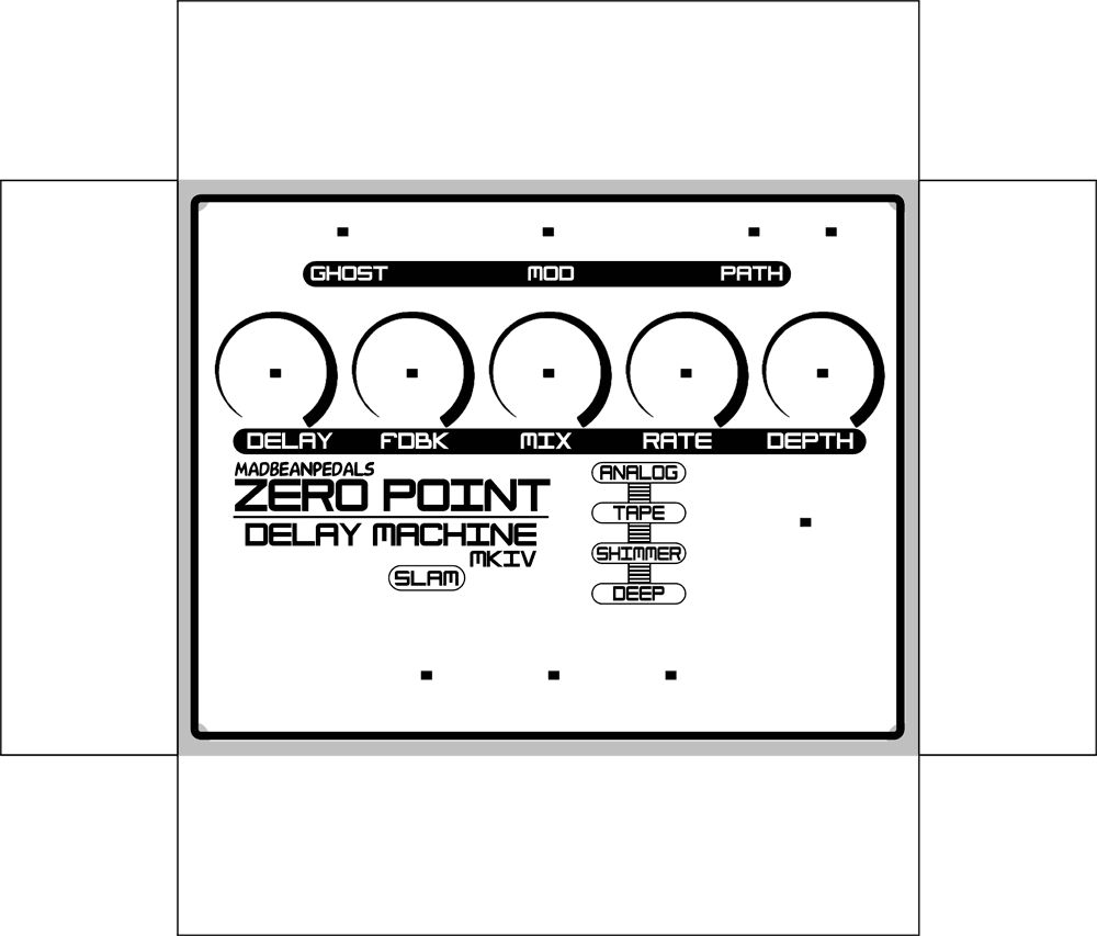 |
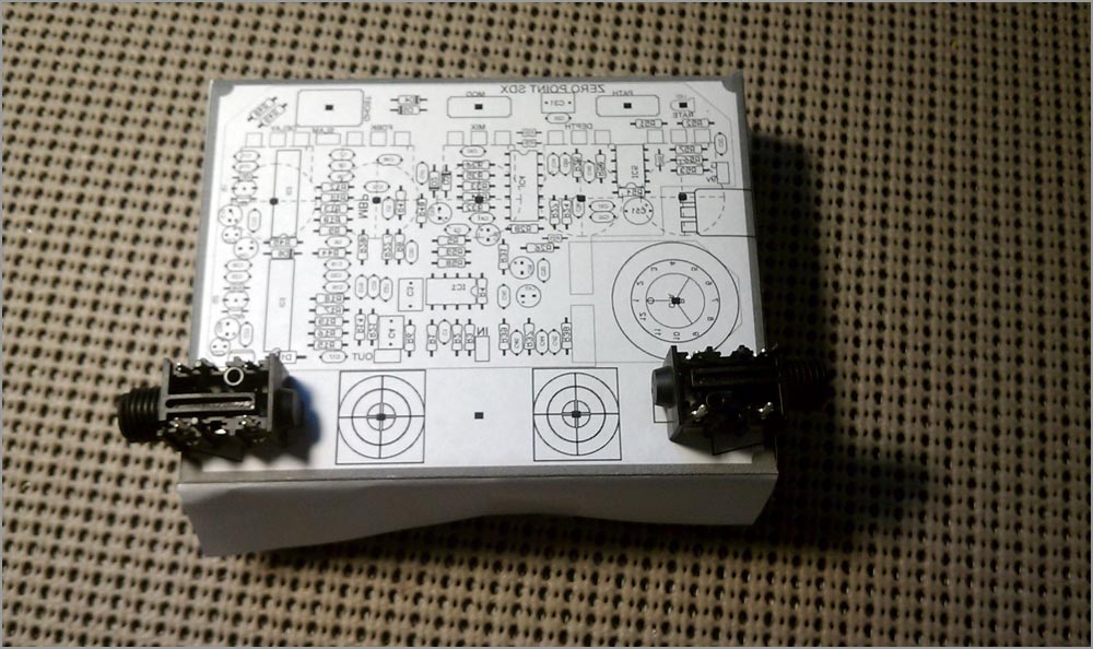
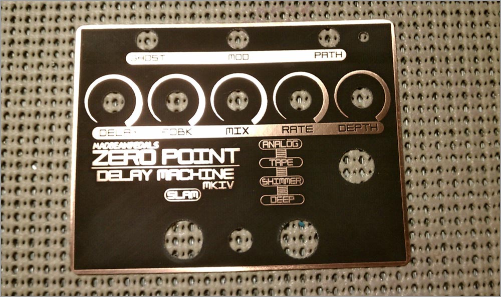
Here’s the artwork I’ve created in Photoshop. This is just a revision of earlier artwork I used when prototyping the project for release. Not terribly fancy, but not boring either. This image was done at 1200 DPI which is the maximum resolution my Samsung printer can handle. That’s enough to keep the text and graphics crisp. We’re not quite ready to do anything with this yet, though. First, we need to drill! |
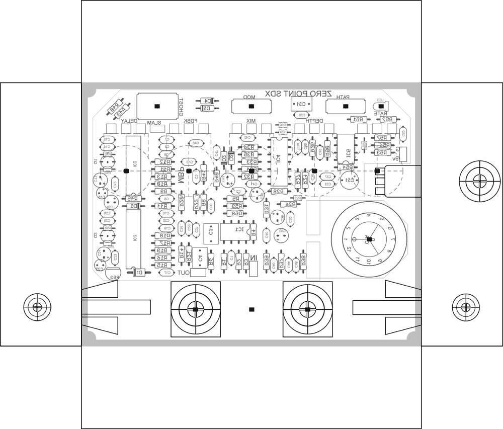
I created the drilling template in the same Photoshop file as the artwork. The PCB image is positioned in the box (a 1590BB) and I’ve made some guesses on the best placement for the jacks and footswitches. I’m using hardware drawings I previously created in my template to move and position this stuff around the image. If I were going to build a lot of these, I would create a very precise template with measurements of the particular hardware I’m using. But, since this is just a one-off the “educated guess” method is good enough. |
 |
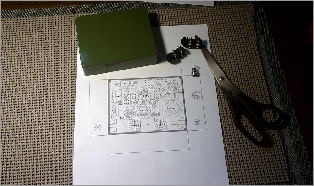 |
The template is printed and ready to cut out. I’m using a dark green 1590BB I purchased from Mammoth Electronics a few weeks ago. I chose a dark color because of the particular way I’m going to apply the artwork (more on that later). I’ve also gathered up some of the hardware I’m going to use so that I can contrast their size with their placement on the template. |
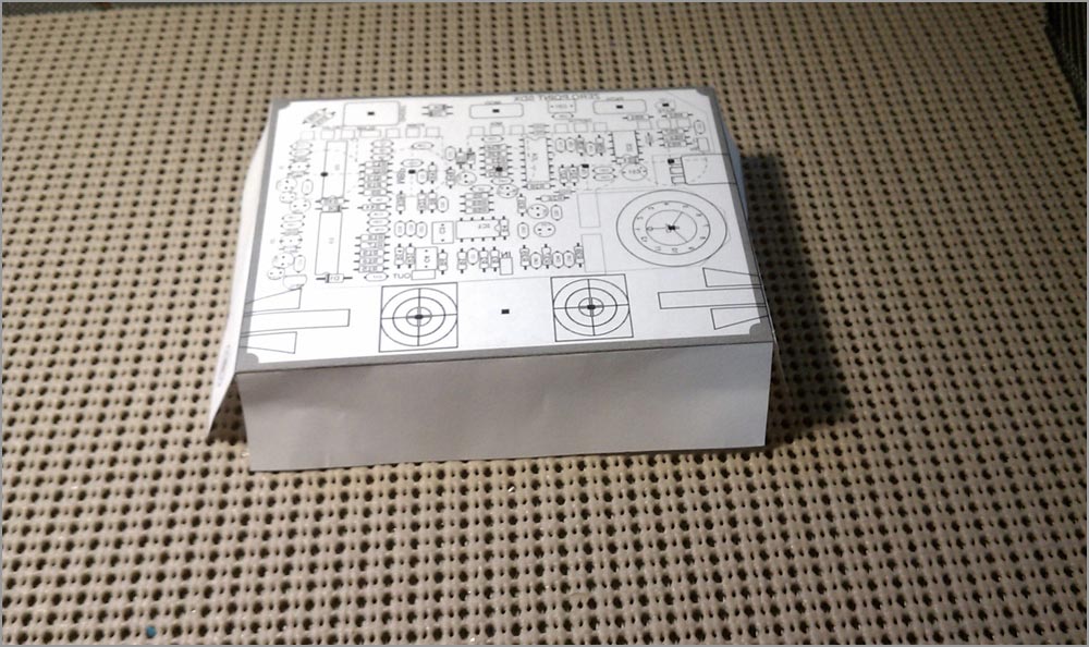
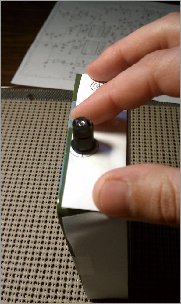
The template has been cut and folded into shape. I use either Scotch tape or the blue painters stuff to affix to the box. A small piece of tape on each wall is enough to hold it securely. |
 |
 |
I’m going to use these particular jacks I bought from Mouser because they occupy less width than the normal open-frame metal ones. This is critical because the PCB is so huge; it’s going to require attention to make everything fit properly. Luckily I have some wiggle room…there seems to be a generous enough space on either side of the jack between the PCB and the bottom wall. |
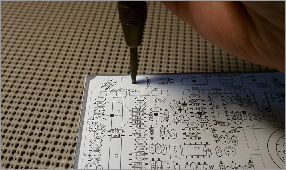
Everything looks good so I’m ready to mark the drill holes on the box. To do this, I use a center punch I bought from Harbor Freight for around $5. I punch one hole for each marker on the top of the enclosure. |
 |
 |
The DC jack is a snap-in I bought from Mouser. Perfect for tight builds where you do not need to use a battery option. The jack has to be placed between the two PCBs AND high enough that it clears the Depth pot. Piece of cake! In fact, I’ve got extra room so I marked the drill hole a bit closer to the edge of the wall. |
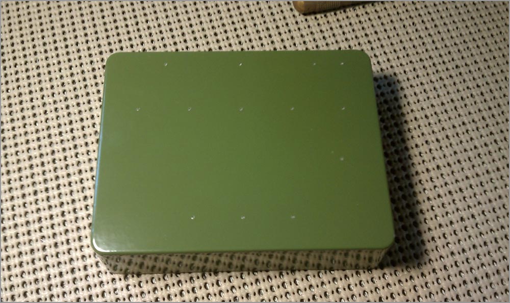
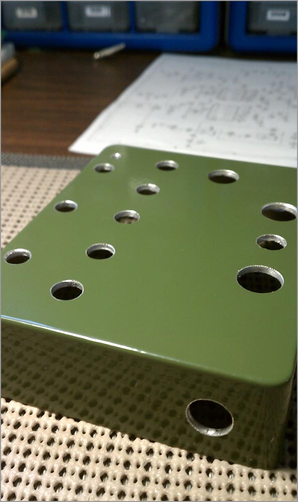
All the drill holes have been marked with the center punch and the paper template is removed. Let’s drill this sucka! |
 |
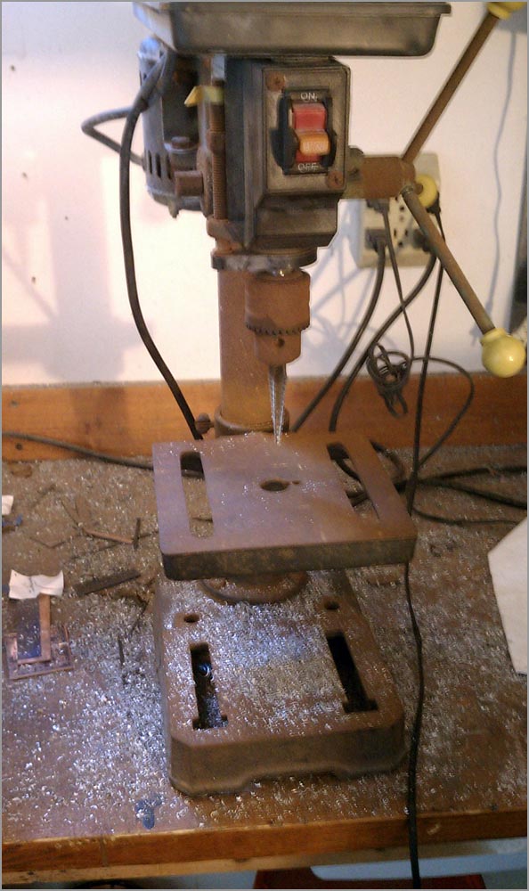 |
Man, this drill press is sad. I mean, look at it. It’s like something you would find in a dumpster; all rusted out, dirty. My workspace has not been cleaned in months either. This is what DIY look like! |
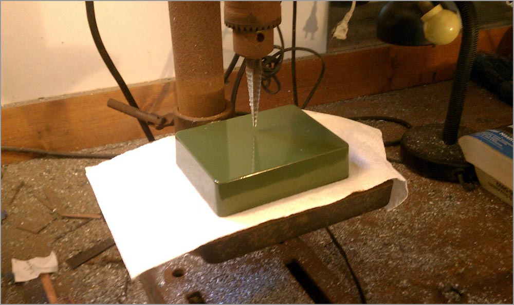
In a normal production process, enclosures are drilled before they are painted. That is if you are manufacturing, of course. For most of us we buy pre-painted enclosures so drilling has to come after the fact. Not a big deal; it just requires a bit of extra care so that the paint does not get damaged when drilling. Here I’m using a paper towel to prevent Rusty the Rustiron from scratching up the paint. |
 |
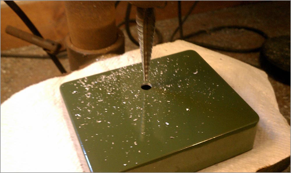 |
The first hole is drilled. Quite messy, eh? Here’s a little secret to making a dense and crowded project fit smoothly: overdrill your holes. IOW, I’m going to drill slightly larger holes than needed for the pots, switches and jacks (BUT NOT THE LED OR DC JACK). This will give me wiggle room in the final assembly so if something is off by a millimeter or two, it’s no big deal. |
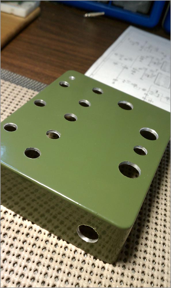
The enclosure is fully drilled. Notice that the drill holes have some burrs on their edges. |
 |
 |
These are removed easily with an Exacto knife run around the edges of the hole. |
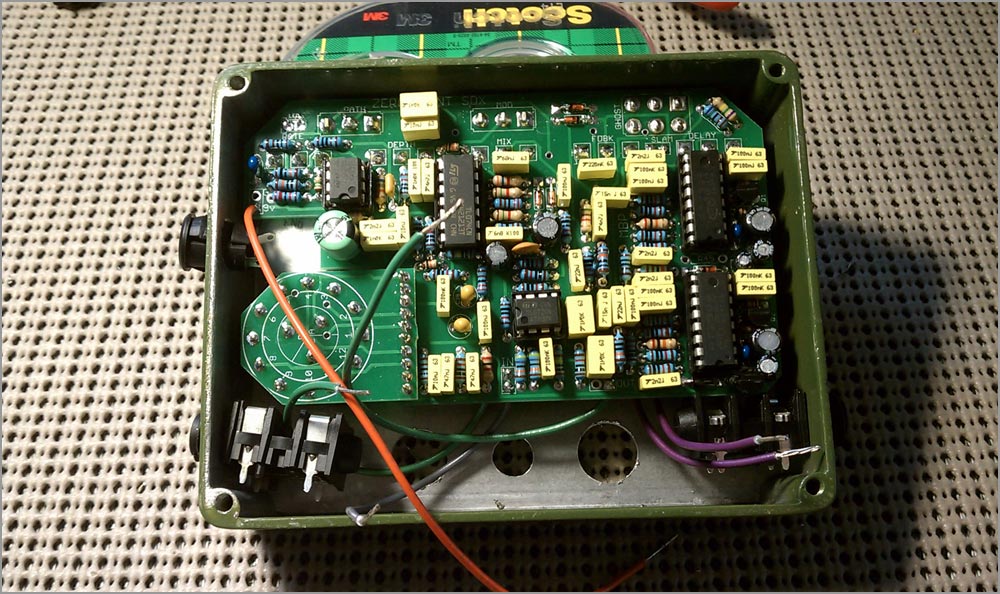
The dry fit. So far it’s looking good. I have clearance between the PCB and jacks and I don’t see any major problem areas. |
 |
 |
I’m going to etch a faceplate for the artwork which will be fixed to the top of the enclosure. I enjoy this method because it is very easy to do and gives the pedal a unique look. Plus, there’s no chance of the artwork getting damaged through use and abuse: it will last forever. |
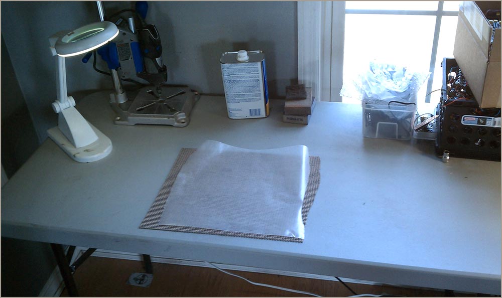
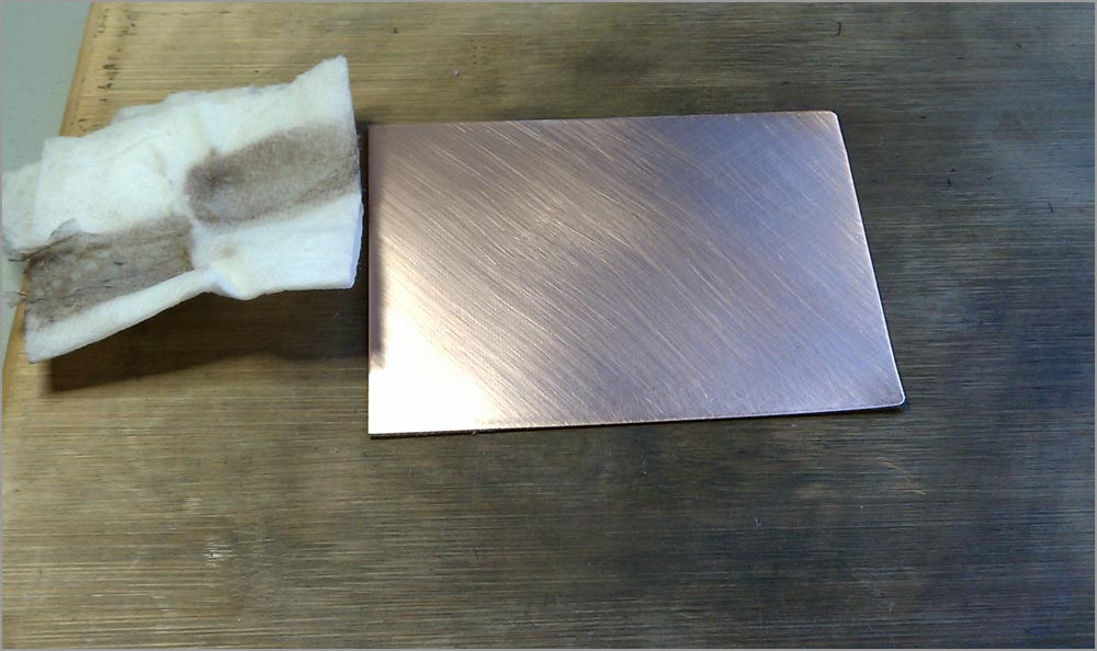
Here’s my PCB making “workstation”; a table, a light, a Dremel Drill Press (not needed here), Acetone, cheap iron and some sandpaper. I’m using some 2oz, super thin black FR-4 which I bought from ABCFAB on ebay a year or two ago. The 2oz is very durable, although it will require extra time to etch. |
 |
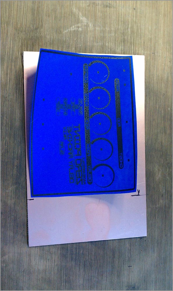 |
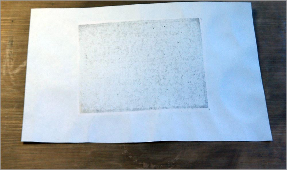
The artwork is printed on Press N Peel Blue and cut to size. Notice that the artwork is reversed when printed? Once it is flipped over and ironed it will be oriented correctly. I’ve marked the edges on the copper clad where I need to cut. This PCB material is thin enough to cut easily with a tin snip. |
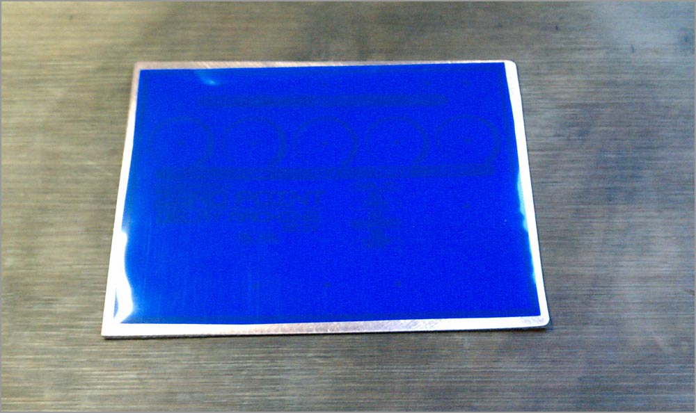
Before transferring the artwork the copper clad must be sanded and cleaned. This ensures a complete transfer of the toner from the Press N Peel to the copper. I use a 3M sanding block to scratch up the surface and then cleaned the copper area with Acetone to remove all residue. |
 |
 |
The PNP is laid flat over the copper. It’s important to make sure both the paper and the copper are completely clean and free of dust or particles. Otherwise, you will be ironing in cat hair to the copper and messing up your artwork! |
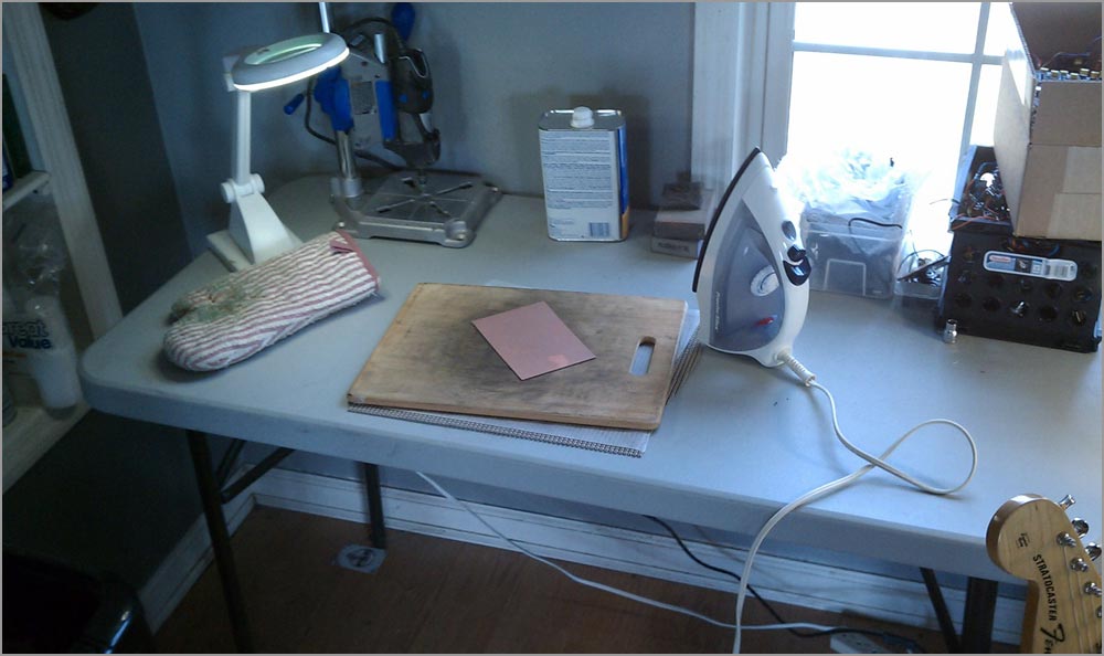
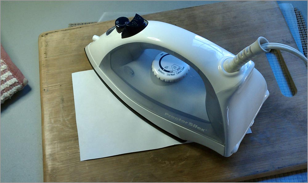
I use a blank piece of copy paper over the PNP and then place the iron on top. The iron is on the highest setting. I’ll leave it on there for about 20 sec. to heat up the surface and start the transfer. |
 |
 |
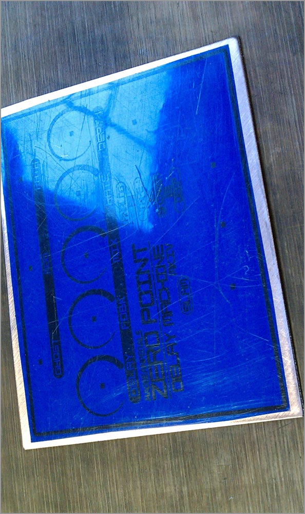
Next I iron all around the copper clad making sure I get the edges too. This is what the paper looks like after two or three minutes. At this point, I will remove the paper and iron directly to the PNP. The goal is to get the toner looking fully black through the PNP. It’s also important not to leave the iron in one spot for too long or the PNP will start to melt. |
The ironing is done. You can see the PNP is pretty scratched up. That’s fine, actually. Those are just surface scratches from the iron contacting the PNP. They did not damage the actual toner transfer. |
 |
 |
I run the copper clad under some cold water for about a minute to cool it down, wipe off the excess water with a paper towel and peel up the transfer paper. Here is the result. Pretty good! But, not perfect. There are a few areas where the black did not fully adhere. |
Luckily, that’s easy to fix with a black Sharpie. I’ve filled in any gaps on the artwork with the Sharpie, plus I scratched up one part of the exposed copper that looked like it had some residue on it. You can see one gap in the border of the “analog” text: I’ll leave that as it is because the Sharpie is not thin enough to draw a clean line over the gap. |
 |
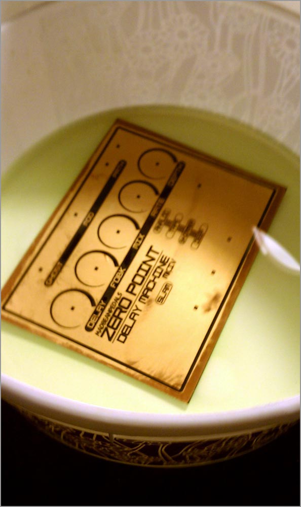 |
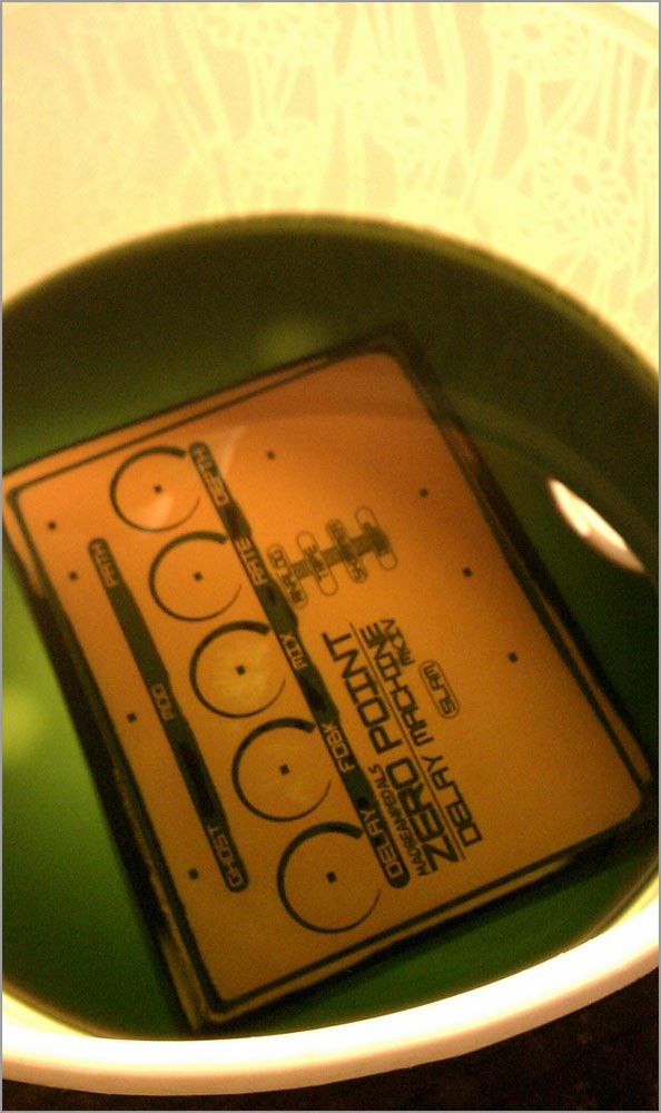
Etching is very simple but also a little dangerous. You have to take proper precautions such as a mask, gloves and protective eyewear. The chemical can harm you and also irritate your skin. To etch the plate, I’m using a 1:1 mixture of Hydrogen Peroxide and Muriatic Acid in a plastic bowel. First the solution is mixed then the copper clad is placed in the bowl and agitated by hand until all the copper is removed. Since this is 2oz material, it will take about 15 minutes. 1oz material takes about 5 minutes. |
After about 10 minutes, my solution is weakening as you can see from the dark green color. As the copper is removed it “loads” the etchant and the acid becomes less potent. That’s okay: a capful of Hydrogen Peroxide added back into the mix will recharge the solution and turn it bright green again. I do this once during this etch. |
 |
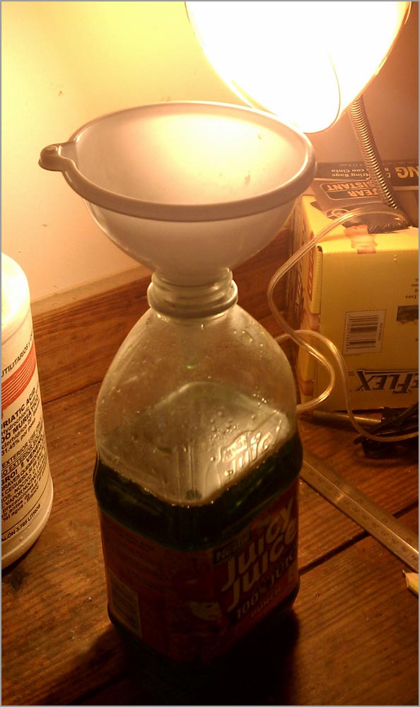 |
The remaining solution is stored in this Juicy Juice container. I use this in case any thirsty burglars decide to snoop around my garage. Seriously though, be careful with this stuff. Ingesting it will surely kill you. |
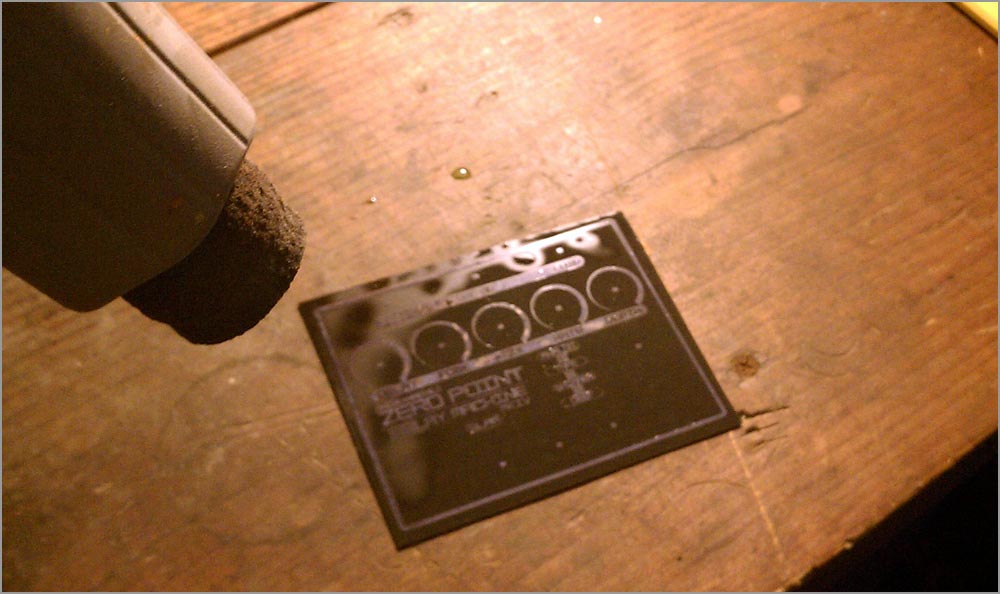
The faceplate is rinsed off with water to remove any remaining droplets of etchant and then dried with a $5 Harbor Freight heat gun. BTW: don’t pour etchant down your sink. It will eat through copper pipes. However, a drop or two isn’t going to ruin you plumbing…just run a lot of water through and it weakens enough not to cause any harm. |
 |
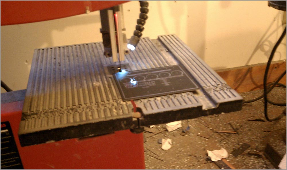 |
After the faceplate has dried I run it through the bandsaw to trim the edges. I do this freehand because I have lots and lots of practice cutting PCBs with a bandsaw. The thin PCB material cuts very easily, too. |
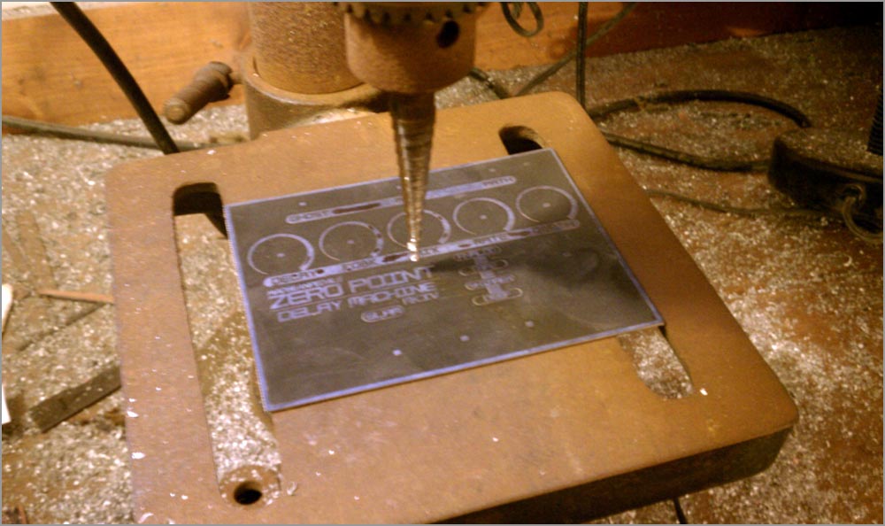
Now the holes need to be drilled out where the hardware pokes through the faceplate. Boy, this is a LOT easier than drilling an enclosure! |
 |
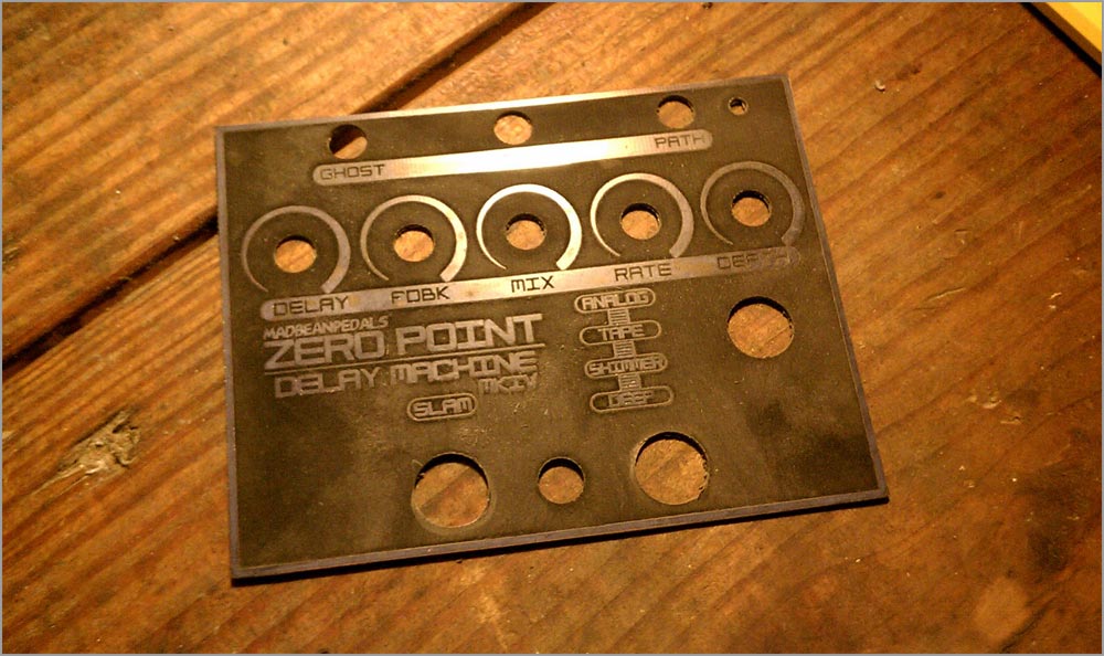 |
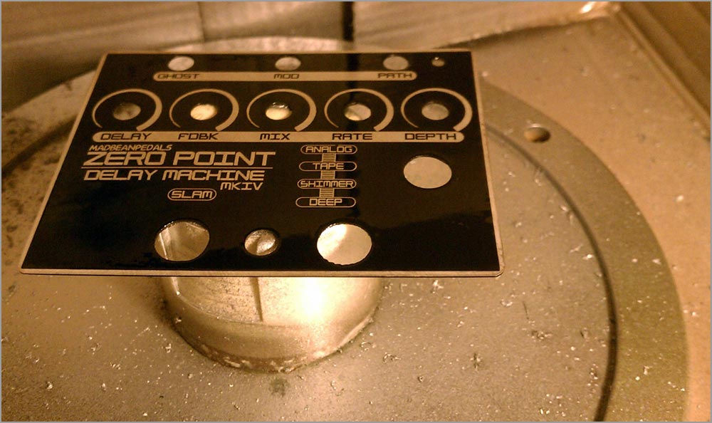
Here’s the faceplate drilled and ready for cleaning. |
Removing the toner is as simple as using a paper towel and some Acetone. It melts right off. |
 |
 |
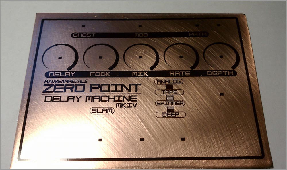
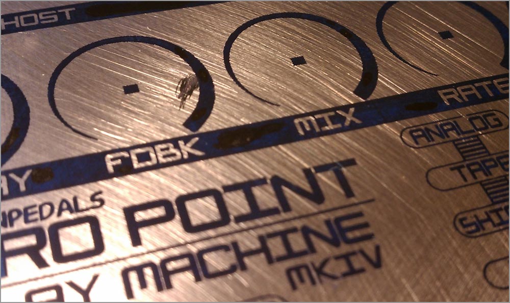
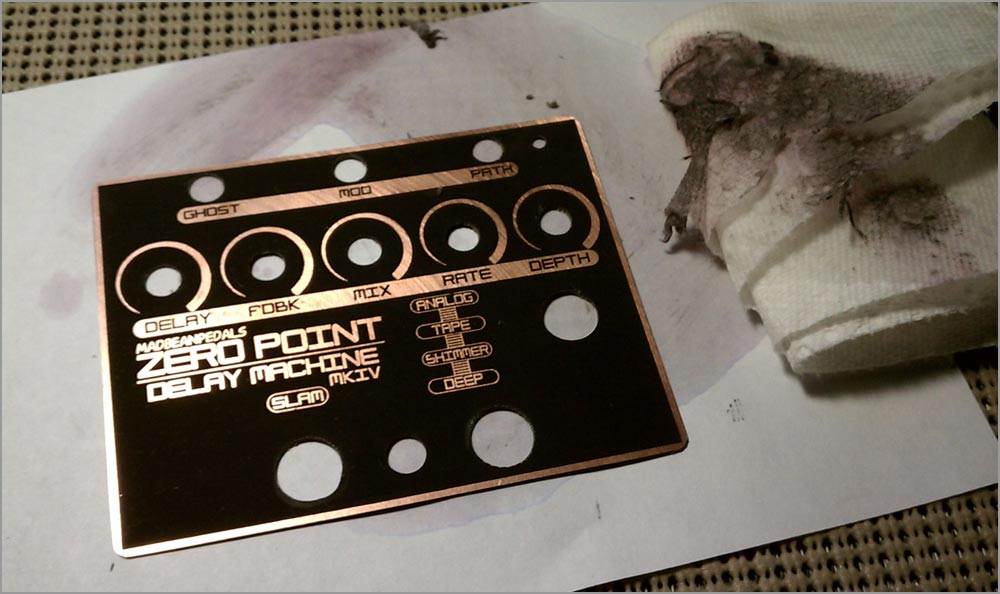
The artwork is looking good, but I think I will go even further with this to make it extra awesome. First, I use some steel wool (the 3M pad version) to do some cross hatch sanding then clean it again with Acetone. This shines up the copper quite a bit. I could leave it like this…but I’m going to go even further. |
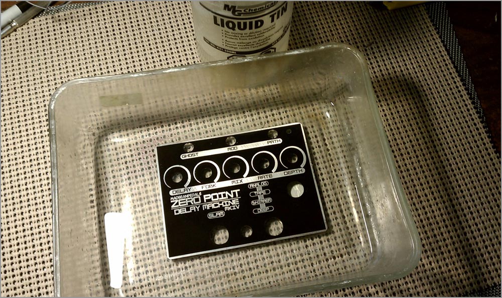
I decide to use some Liquid Tin to tin the bare copper. This gives it an amazing aluminum-like finish. After about 5 minutes of the Tin bath, I wash, dry, sand and clean the faceplate again. |
 |
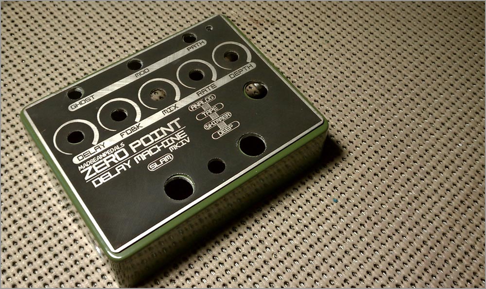 |
I could leave it like this and go straight to assembly. Even though the faceplate looks amazing now, the tin coating will start to oxidize in about a week. To preserve the shine I decide to hit it with some clear coat. |
| Here is my painting station back in the garage. A carboard box and a rotating plate I bought from Walmart. |  |
 |
The clear is applied in two coats with about an hour in between. I’ve leave this to dry overnight. In addition to preserving the shine of the liquid tin, the clear coat also deepens the black of the PCB material. It looks very professional, now! |
| Stay tuned for the third and final part! | |
 |
 |
 |
 |
 |
 |
 |