Last spring a musician approached me and asked me if i could build him an octaver. Told him i never built one but was very willing to give it a try, and so i went with the Lowrider. He also asked if there was a way he could footswitch the octaves; i posted a topic in that regard.
So here'e the finished build i'm about to give him :
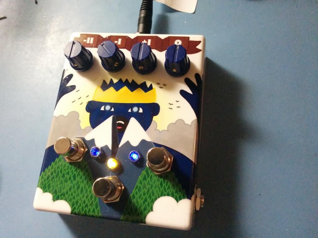
Left footswitch is for both the lower octaves, right switch is for the upper octave, and middle switch is bypass (duh!). I let you figure what are the LEDs here for.
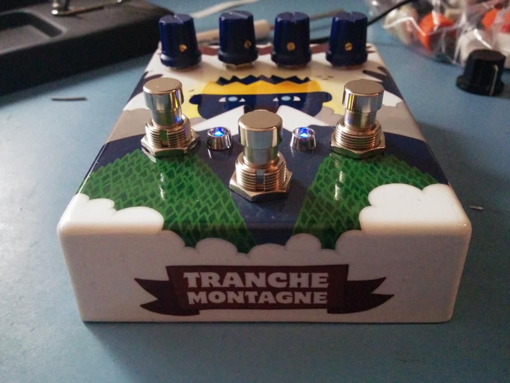
The desing of the waterslide decal is all made by him. He named the pedal "Tranche Montagne" which could be translated as Mountain Slicer. He was inspired by some old folks legend here in Québec about a giant slicing mountains. So what has it to so with an octaver... simply because why not!
Another thing i have to give him all the credits is that he did all the drilling templates. The guy never ever made any DIY project, and all by himself he figured that he would need a Hammond 1590BB, and from there, positioned all the components for the tamplate. I was totally amazed.
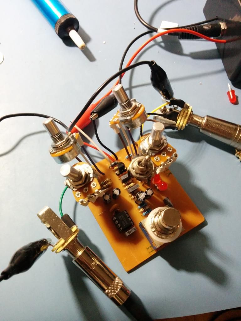
For the MODs i had to do to add some footswitching, i went this way, which in terms of wiring the thing, looks something like this :
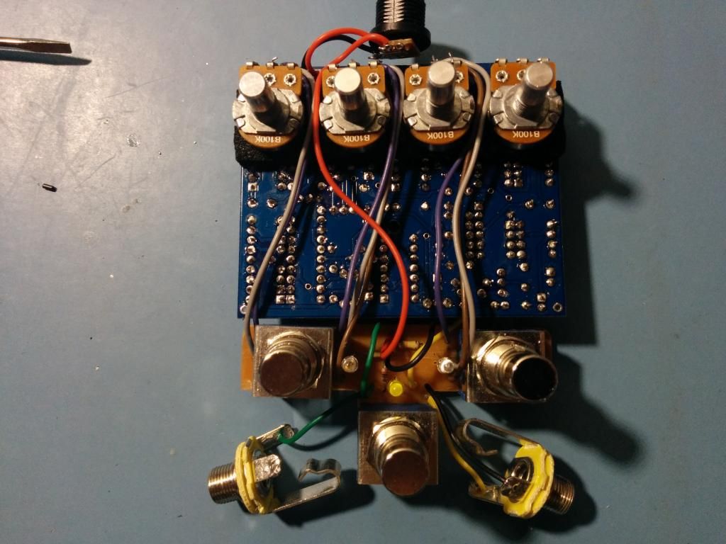
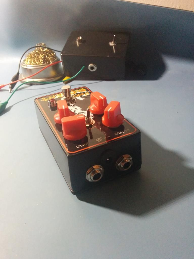
Finally, the the whole thing put into the box looks like this :
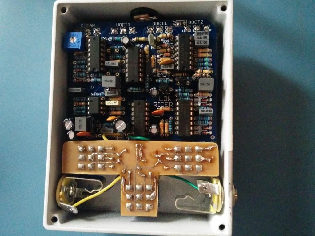
As you can see, it does fit in, but it's real tight. I must have spent an hour if not too with him, looking carefully at his template to make sure everything would fit in. Just look at the DC jack, i even had to fold its pins!
I'll meet the guy next weekend, in the meantime, i'll test it with my own gear to make sure it doesn't have any problems before i hand it to him.
So here'e the finished build i'm about to give him :
Left footswitch is for both the lower octaves, right switch is for the upper octave, and middle switch is bypass (duh!). I let you figure what are the LEDs here for.
The desing of the waterslide decal is all made by him. He named the pedal "Tranche Montagne" which could be translated as Mountain Slicer. He was inspired by some old folks legend here in Québec about a giant slicing mountains. So what has it to so with an octaver... simply because why not!
Another thing i have to give him all the credits is that he did all the drilling templates. The guy never ever made any DIY project, and all by himself he figured that he would need a Hammond 1590BB, and from there, positioned all the components for the tamplate. I was totally amazed.
For the MODs i had to do to add some footswitching, i went this way, which in terms of wiring the thing, looks something like this :
Finally, the the whole thing put into the box looks like this :
As you can see, it does fit in, but it's real tight. I must have spent an hour if not too with him, looking carefully at his template to make sure everything would fit in. Just look at the DC jack, i even had to fold its pins!
I'll meet the guy next weekend, in the meantime, i'll test it with my own gear to make sure it doesn't have any problems before i hand it to him.