News:

Forum may be experiencing issues.

Main Menu
Menu

Show posts

This section allows you to view all posts made by this member. Note that you can only see posts made in areas you currently have access to.

Show posts Menu

Topics - pk1802

#1
Open Discussion / Tap tempo tape delay... With real tape?
September 20, 2013, 05:20:04 AM
Forgive me if this is in the wrong spot.

I just picked up a Univox EC-80a - non-working - from ebay. The non-working part will hopefully get sorted out on my workbench soon, but to my real question.

I use delay when I play live, and I always need to have a tap-tempo on my delays. I have a couple that get set and left, but for versatility, I like tap tempo.

Here is my question: Have any of you seen a Taptation implemented for controlling a real tape delay?
Is there any way to calibrate the Taptation? I've read every document I can find, and I see mention of calibration, but I've not seen any instructions on how to do it.

Thanks gents.
#2
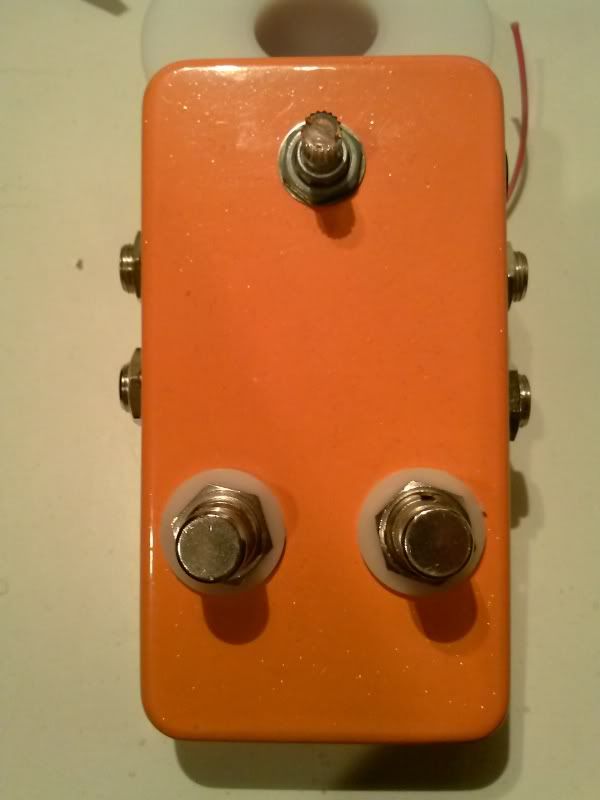
This box is from a failed project that was attempted, but never accomplished, many moons ago.

I think it was supposed to be a true bypass looper and wet/dry loop together, or something weird like that.

Now I have a box with two 3PDTs two sets of jacks and one knob(the light up knobbie can go if I need more space). Every time I walk into my work space, it's sitting right there, staring me down, mocking me for making it the mutant that it is.

I was thinking two different boosters. I already have a lpb1 and a couple germ boosters, both in one box would be nice, but I am sure there are some better ideas. I could also flip the box and do one switch where the pot is and use the holes for the switches for pots.

What say you madbeaners? Any idea of what I can jam into this box? I am ok with using the battery area for circuit board area.


#3
Mods / Dirtbag Deluxe - Reduce Modulation?
May 22, 2013, 03:42:24 PM
I've searched around the forum, and I didn't find any info on this, but if it's out there, I'm sorry.

I've just recently built up a Dirtbag and the modulation settings are only useful to me in the first quarter of the modulation pot rotation, the rest of the pot rotation is much too seasick for me. Any suggestions? Should I switch the Mod pot out for a 100kA?
#4
Build Reports / Dirt Bag Deluxe
May 21, 2013, 01:41:09 AM
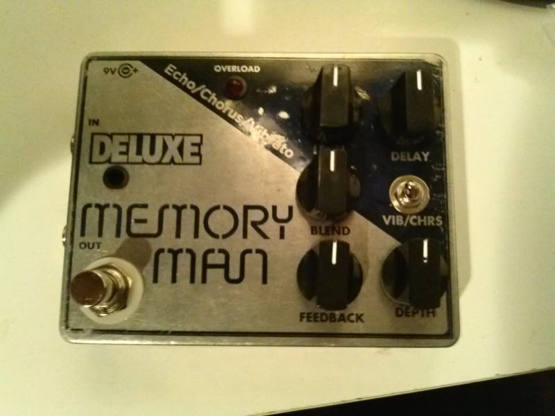
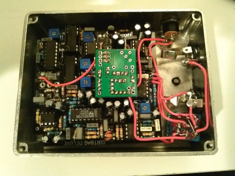
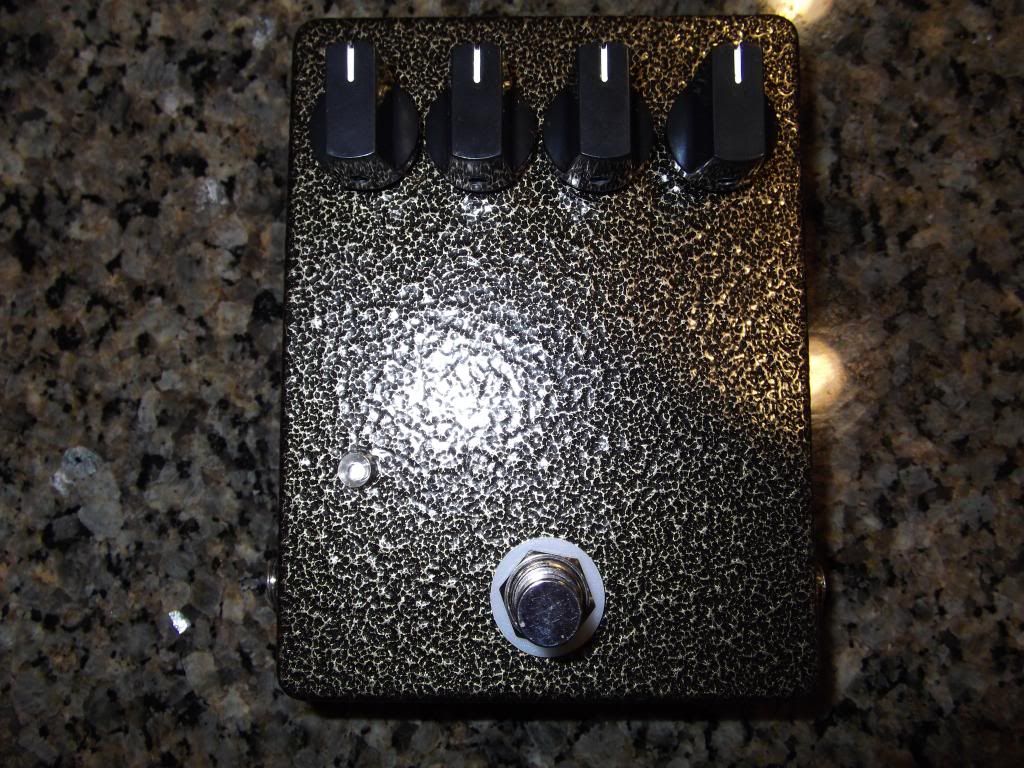
Been working hard at this one. I had it finished the other day, but the caps I had on my roadrage were too big so I had to swap them out for low profile caps from mouser, and that took a few days.

I have MN3005s in her, I THINK they are the real deal. I'm getting delay at 122bpm which I believe is 492ms. Hopefully someone who can math properly will tell me if that is right.

I got the graphic from someone here, I was going to etch the box, but I messed the transfer up a little bit, but I liked how it looks. Looks like someone has been loving it for a while. So I decided to keep it. I didn't even clearcoat it because I want it to take a beating.

Also, I left off the LED because I haven't decided which color I want go with, and I was too excited to try it out.


#5
Tech Help - Projects Page / Current Lover - Noise
May 11, 2013, 03:14:07 AM
Hello gentlemen,

I've built myself up a Current Lover with a MN3007 running at 15v with a tl1054 roadrage(pulled pin 1). I've used both a switching supply(like the godlyke powerall) and a transformer based supply.

I am getting a lot of lfo noise. I am getting modulation, so that is nice, but the noise makes it unusable. MN3007 is good, I tested it in my Collosalus. I've adjusted the trimmers multiple times, no help. Is there a quick fix like on the Collosalus where I can just swap out some diodes and be done with it? or do I need to do more hunting? I can post IC voltages if need be.

Thanks
#6
Build Reports / Non-MB -- Shortstack/Hotcake
March 11, 2013, 12:04:16 AM
I finally sat down and got this little guy boxed up. I like it a lot, although there is a bit of fizzyness on the note decay(in normal and bluesberry mode with every opamp I've tried).

Shoving everything in there. I had to grind the edge of the lid because I mounted my power jack to close...


It's a tight fit with that switch in there...


My girlfriend painted this one for me. My idea was just for her to paint a stack of pancakes, but her (literal) hotcake was a much better idea. Here it is getting a test drive next to my honeybee clone...

#7
Build Reports / Collosalus Almost Done - Clock Noise
January 06, 2013, 12:40:28 AM
I finally got around to finishing off my Collosalus. The Holiday season took the wind right out of my pedal building sails.

When I first built this bad boy, I boxed it before I rocked it and it didn't work. I took it apart and found that I forgot to solder one single pin from IC1, which happened to be the pin where the signal goes into it. FAIL.

I got the pin soldered, checked it, and I have sound, and flange. Which supprised me, becuase I bought some cheap 3007s, thinking that for a couple bucks I would give it a shot.

Outside - It's one of the Vein colors from PPP, I bought it so long ago I can't even remember which one.


Inside - Not my neatest wiring, but I already had to take it apart once, so I don't care at this point.


I'm getting some clock noise in the pedal, I didn't socket c22 like the build doc suggested, again, FAIL. Should I desolder and throw some sockets in there and play around with different values? Or is that not the problem? Everything is stock except that I changed out both of the 15uf caps, one is 10uf one is 22uf.
#8
Open Discussion / I wish I could rock this jacket.
December 05, 2012, 08:12:24 PM
http://blog.makezine.com/2012/12/05/disco-jacket-responds-to-guitar-licks/

Literally and figuratively.

What do you guys think? I feel like I would get beat up if I tried to wear that while playing in dingy clubs.
#9
Tech Help - Projects Page / Collosalus Cap problems
November 17, 2012, 08:15:13 AM
I searched around the forum and didn't find any answers, so I figured I'd ask the gurus here.

1. I'm building a Collosalus right now, and for some reason, I ended up without 15uf caps in my order.

Can I used a 10uf here, or should I hold off and order some 15ufs with my next order? I could maybe squeeze a 10uf and 4.7uf in parallel there, would that work?

2. Same build, different question. Do both C20 and C27 need to be 25v caps because of the charge pump, or can I get away with using 16v caps there?

You guys rock!

Thanks
#10
General Questions / Looper/blender problems
August 22, 2012, 02:29:43 AM
Hey guys,

I'm having some problems fleshing out an idea that I had. I've failed miserably at coming up with a wiring scheme on my own, and I've done some looking around but can't seem to find a schematic or wiring diagram of what I'm looking to do.

What I'm trying to build is a mix between a true bypass loop and a blend/mix pedal.

Ideally I would have two switches the first to toggle engage/bypass the loop, and the other to change the loop from a blender(I have the blend circuit done) mixing the pedals in the loop in with my clean tone, or adding the pedals into my clean tone in series.

Does anyone know if something like this is possible? Or if there is a wiring diagram floating around for this setup that I just can't seem to find?

You guys are awesome, and I read this forum every day soaking up new ideas.

Thanks
#11
Build Reports / Non MB - BSIAB 2
May 28, 2012, 07:57:34 PM
Hello gents,

I'm slightly new here, I've been creeping for a couple months. I figured that I'd post some pictures of my creations. Well, I'm not quite smart enough to create the circuits, but I am lucky enough to stand on the shoulders of the incredible people of this community.

I just finished this build so I thought I'd share. I have some Madbean builds coming down the pike. Next on my list is a Yellow Shark.

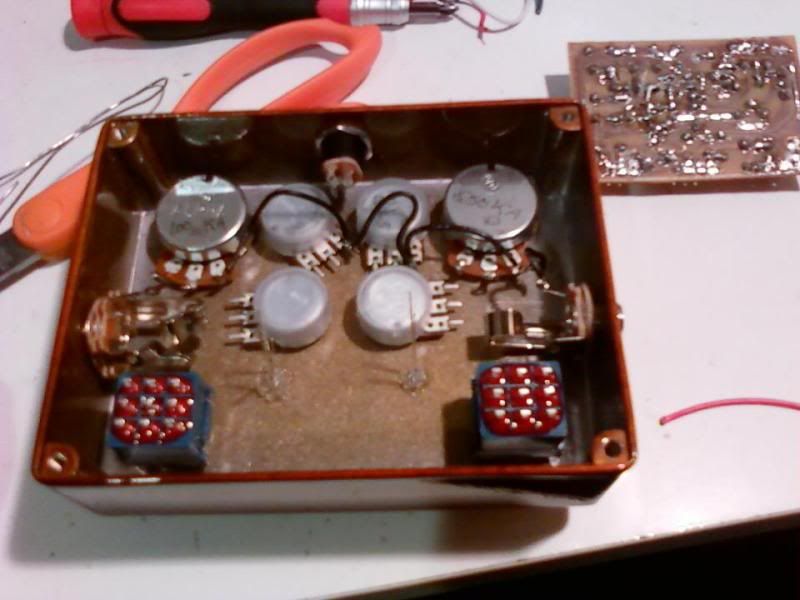
Took this right when I started to wire it up, figured I'd take a before and after.


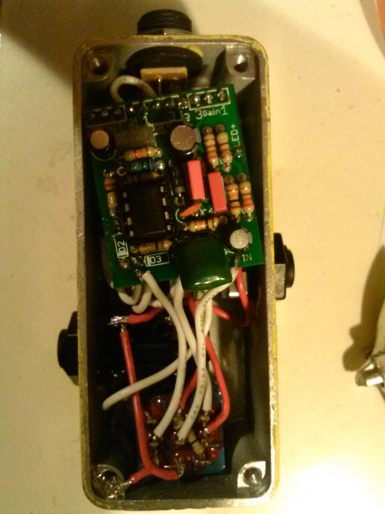
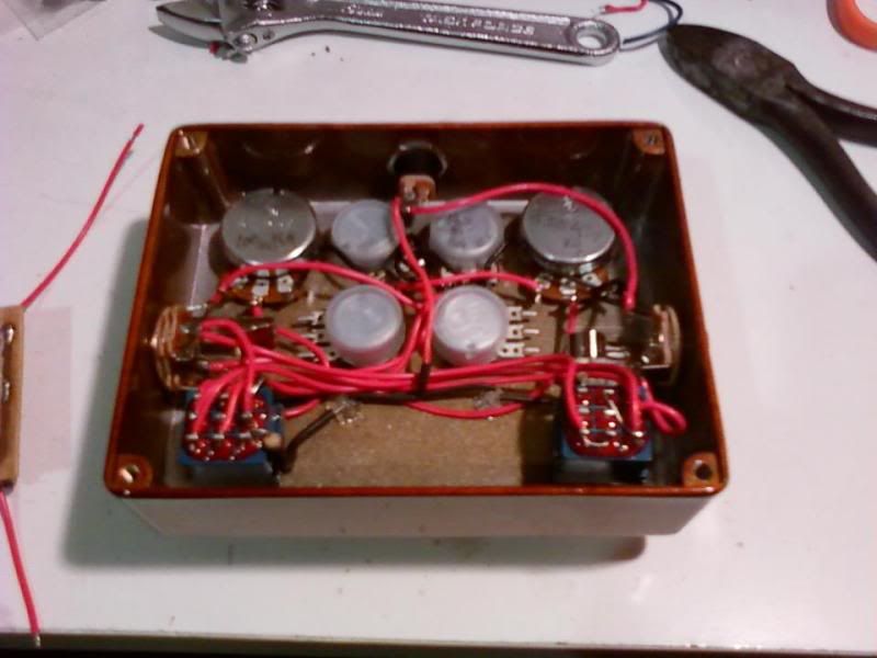
This is the "after" although this is only the wiring that did not attach to the board. Hopefully my wiring isn't too messy for you gents, I've been doing this for a few years, but my wiring never seems to improve.


I didn't take a picture with the board and the rest of the wiring, I forgot. If you guys are interested, I'll open her back up and take another picture.

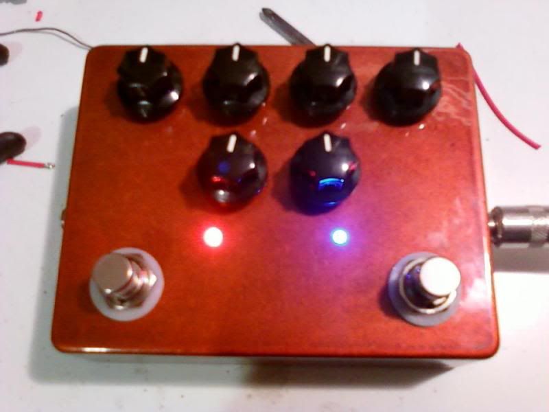
This is the front, I believe the color is copper from PPP, but it was actually a blem. I planned the knob placement to best cover the blemishes.

The extra 3pdt is for switching between two sets of Volume and Gain knobs. So it feels like I have two "channels" on the pedal to use with a bi-color blue/red led to let me know what channel I am on. The tone and mids knobs are shared between the channels.


Let me know what you guys think. Ideas? Constructive criticism? Snooty remarks? I'm game for anything.
#12
Hey guys,

I etched myself a Sunking and built it up, but I'm having a problem with the tone control.

It seems to not be doing anything to the effected output.

Both the bypass and effected sound are very close to another Klone I have lying around, so I figure everything else is working fine.

I've poked around a little bit but didn't find anything. The Pot itself is functioning correctly, and I've gone over the entire board twice reheating every joint.

All of the 1uF caps in my build are Box caps as that was what I had on hand, could this be my problem?