News:

Forum may be experiencing issues.

Main Menu
Menu

Show posts

This section allows you to view all posts made by this member. Note that you can only see posts made in areas you currently have access to.

Show posts Menu

Messages - tatou

#1
Dunno if this is from juansolo or not, but I did manage to track down this blog post which seems to address the question:
https://obsoletetechnology.wordpress.com/projects/studio-electronics/dc-dc-bipolar-power-supply-for-effect-pedals/

The tricks is a DC-DC converter, in particular a LT3467 chip (mouser data sheet). Appears to not be available in a thru-hole package, so tougher for DIY builds. But figure I'd share!
#2
Thanks for the reply alanp.

I realize that running +/-12v off of +9v, in general, is not a practical idea or solution (I have 2 small modular setups and a semi-modular that all run on their own 12-15v bipolar supplies). But in the spirit of DIY exploration (with some real practical applications), I'm trying to learn how this would be possible, or what the options are...
#3
To make things a little more concrete, here's a schematic for a pedal<>Eurorack interface (source) one might want to incorporate into a pedal enclosure with a 9v pedal supply ("TILE" refers to the Eurorack module):

#4
Hi! I've recently been getting into modular synths, but since I already have an arsenal of guitar pedals I'm not letting myself get any effect modules, instead relying on ways of using pedals in my Eurorack patches.

To that end, I've been researching how to design things that bridge the two worlds, taking inspiration from the Boredbrain INTRFX & Transmutron, the Hungry Robot Modular pedal line, and various DIY "pedal I/O" circuits.

Those pedal interfaces can use Eurorack control voltage (and audio levels), but are powered by regular 9v negative-tip pedal power supplies. Any ideas how to accomplish that? One idea is a TC1044 charge pump for a bipolar 9V supply, and just assume you don't need the extra headroom that the standard +/- 12v Eurorack power supplies. Any other thoughts?

I already asked in a couple of modular synth forums and it's just been crickets...

Thanks!
#5
I was just skimming the new MBP offerings and studying the VFE Fuzz Duo schematic.

This circuit includes an inductor in series with the input, which reminds me of the transformer in front of the FolkUrban variant of the Bazz Fuss, which in turn is nicked from this AMZ article on Guitar Pickup Simulation.

Still learning EE basics, so a few questions:

  • Does the inductor in the Fuzz Duo serve the same purpose as the FolkUrban/AMZ transformer (and is a transformer really just two inductors)?
  • That is, does it adjust input impedance to help the fuzz function well after buffered effects without losing tone?
  • If so, why is an inductor better at raising input impedance for this use case than a resistor?
  • If not, what does the inductor do?
  • What about the two inductors to ground off the Q1-Q2 emitters?
  • How does one select the value of an inductor/transformer for this purpose?
I've got an experimental "fuzzstortion" on the breadboard right now and wondering if adding an inductor or transformer would help it play well with other effects. I don't have either of these in the parts stash, so wondering if it's worth a Mouser order to play around with...

Thanks!
#6
Oh, i hadn't even noticed that Tayda sold enclosures! I've never actually ordered from them before as I've seen mixed reviews of quality control. But I did just start a cart today with standard diodes/transistors/ICs, so I might add a few enclosures in wacky colors to the mix, too. Still no sparkles, though. :)
#7
Well, at this point I'm more interested in building really swell-looking pedals for myself as a hobbyist, no plans to go into production building just yet. :)
#8
In the past, I've used Pedal Parts Plus and Mammoth Electronics to order enclosures with nice sparkly/veined/hammered/translucent/etc. finishes.

However, Mammoth is now out of business and PPP has moved to a bulk only business, where you need to order at least 25 the exact same customized enclosure.

Other than the flat-color or black/white powdercoat options in some sizes from Small Bear or Love My Switches, does anyone have suggestions for affordable, nice-looking sources of finishes that are a little more "special"? :)
#9
I'm still running EAGLE 7.7 (3 years old) and just happened to the website just today (curious about whether or not to upgrade)... and saw this!

It looks as though there will still be an "EAGLE Free" version for use by hobbyists with the same/similar constraints (2 signal or plane layers and 80 cm² board area; which is plenty for most pedals). At least, that's how I read it...?

I've been thinking of switching to KiCad for a year or two to go fully open-source, but the learning curve for EAGLE was high enough as it was, and I've also come accustomed to the Madbean EAGLE Library (can that be converted to other platforms?). Is there a good tutorial aimed at pedal hobbyists for KiCad? :)
#10
Thanks all! There's also been a good discussion on DIYSB.

Apologies thesmokingman, you're right. Perhaps this wasn't the most appropriate forum for dev help. In the past, I've had more luck getting my questions answered here than at DIYSB or FSB, but in the past I've mostly been modding MBP projects (and I did use the hipster schematic as my FF reference for this experiment!). :)

Mods, feel free to disable this thread if it's too off-topic.

QuoteThe 5th gear schematic is actually wrong. Take a very close look at the muffer (or the big muff). There's a very, very important distinction between your circuit's diode feedback and the Big Muff's. The fact that something's only clipping half your waveform is a big clue. I am currently not going to give more than a hint though because I think you have the capacity to figure it out for yourself.

midwayfair - If you're hinting at the capacitor in the muffer/BMP schematics (;)
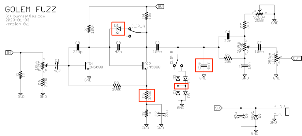
?), I did try wiring things up that way but it didn't matter. Voltage still only seemed to clip in one direction. However, someone on DIYSB reminded me that transistors can be wired as diodes... the 2n5088/89 forward voltage was around vf = .75, way below the LED's (vf = 1.6). When I tried a Si (vf = .62) or Ge vf = .45) diode going from the Q2 base to collector, I did get clipping. So I assume that's what's going on... unless I'm missing something?

Still planning to experiment with different ways to bias Q2 though...
#11
I've been breadboarding an experimental fuzz, combining some ideas from the fuzz face, muff fuzz, bazz fuss, and even the big muff.

Here is the current status of what I've hacked together (my "question areas" are boxed in red):


Quick overview:
* It's essentially a fuzz face topology (with tweaked values) running into a modified AMZ presence tone control
* The fuzz is controlled by an input pot rather than the normal fuzz control (e.g., R5 as a pot)... I found this to sound better & be more reliable
* A switch toggles between a single LED in the Q2 feedback loop vs. silicon hard clipping
* The amplifier output comes directly from the Q2 collector, unlike a typical fuzz face

It's sounding great, but I still have a few questions about how parts of the circuit work, and hope some of you can help me understand my own frankenstein a bit better!!

D1: WHY DOES ONLY ONE DIODE DO ANYTHING?
At first, I wired up two LEDs in a symmetrical typical clipping fashion, as in the big muff, etc. But I noticed only one LED lit up. With further experimentation I realized only one diode going from collector to base on Q2 appeared to do anything at all. The other direction simply has no perceivable effect. This is how things are wired in the bazz fuss, but I suspect you can actually still use symmetrical clipping in a single-transistor circuit like that (e.g., I've seen it in the muffer or 5th gear overdrive). But I'm wondering if there's something particular going on with the coupling of transistors in the FF topology (rather than having two distinct "stages"? Could it be that the feedback loop via R3 is somehow affecting the voltage swing in such a way that only one diode ever matters? If so, is this not a clipping diode in the conventional sense? It really does sound different... and the hard-clipping diodes to ground work in both directions. What gives?

Regardless, that single LED sounds great. It's a harsh, sputtering bumblebee-type fuzz, whereas toggling to the hard clipping network has a creamier distortion feel (and no diodes at all is a beefier, more open and uncompressed fuzz, and of course more output). The tone controls help balance out some of the tonal differences between those three "clipping" options.

R5: THIS SEEMS TO BE THE ONLY WAY TO GET A GOOD SOUND OUT OF THIS CIRCUIT
There's no equivalent to this resistor in any other schematic I've seen... but if you jumper it and go straight from the Q2 emitter to ground via R8 and C2, the pedal sounds... starved. Like the battery is nearly dead or something. The fact that R5 is even there is a happy accident, a breadboarding vestige from experiments getting a fuzz control to sound good in this part of the circuit. If any of you have any thoughts, please let me know!

D2-D5: SUBLE MULTIPLE CLIPPING DIODE QUESTION
I drew things here on the schematic as I accidentally breadboarded it up... with the anodes of D2/D5 touching the cathodes of D3/D4. In this way, it seems like some current can skip D3/D5 without going all the way to ground, but then I couldn't hear any difference when I "fixed" it (D4->D5 and D3->D2 directly, with no point touching in between). The only other place I've seen this is in some (but not all) Timmy schematics floating around. Does it matter to have this connection point between diode pairs in opposite directions? Why or why not?

C10: HOW DO YOU REALLY CUT HISS?
Adding this cap to ground seems to help cut a little bit of high-end hiss/noise out of the circuit (although probably not even enough to bother with the parts count)... However, it doesn't appear to me to be a proper low-pass filter. Any thoughts on why this works or what I should be doing instead are welcome. :)

The rest of the circuit I feel like I understand pretty well. It's a little low on output... if you dial the fuzz & tone knobs back and crank the volume to max, the effect is on par with unity bypass volume. With everything cranked there's quite a bit more headroom. Based on my research, a fuzz face adds 18db of gain and a BMP-style tone stack attenuates 7-15db of that, and with diodes on that cuts into things a bit more.

Any other thoughts you have about this circuit and how to improve it are welcome. So far it's proven to be a fun, versatile little beast!

Thanks!
(And apologies for cross-posting to other boards)
#12
Resurrecting this topic — does any one know if this "fail switch" mod would work for the more recent (2015) CaveDweller as well?http://www.madbeanpedals.com/projects/_folders/1590A/pdf/Cave%20Dweller2015.pdf

I have one of those boards laying around and am thinking of trying some mods to it...
#13
Thanks!

After a bit more research on the circuit I realized that it was negative ground, and I found some NPN schematics but they required positive ground! :) I breadboarded it up using some PNP silicons I had on hand and think it sounds pretty killer that way, so I'm going to go ahead and move forward with that. I'll socket the trannies and maybe might pick up some germaniums try out later.

Some other mods I made, in case anyone is interested:
* omitted the "fat" switch mod & C7 (10u).... it didn't sound pleasing with my setup
* changed "STAB" pot to 10kB
* added a "wonderfully stupid tone control" with a 100n cap at the end
#14
Tech Help - Etcher's Paradise / NPN version of Zombii?
December 27, 2018, 08:23:33 PM
I'm considering building Zombii (Fuzz Factory variant):
http://madbeanpedals.com/EP/schematics/Zombii.gif

On hand, I have a few PNP silicons but I also have a pair of NOS NPN germaniums that have been gathering dust for a couple years. I feel like at one point I knew some tricks for adapting PNP circuits for NPN, but it's been too long. Anybody have any tips? It should be possible, right?
#15
Open Discussion / Re: Autodesk buys Eaglecad?
March 13, 2017, 09:19:45 PM
Just now getting up to date with this development.

For now I can stick with EAGLE 7.5, but I've been tempted to try and learn KiCad anyway.

Does anyone know if EAGLE libraries can be imported into KiCad? In particular, I've taken the madbean library circa 2014 and modded it heavily for my own use... is there a way to use these for schems/boards in KiCad?