News:

Forum may be experiencing issues.

Main Menu
Menu

Show posts

This section allows you to view all posts made by this member. Note that you can only see posts made in areas you currently have access to.

Show posts Menu

Topics - Om_Audio

#1
Adapter is 14V/800Ma
not sure center pin polarity yet
(replacement adapter cheap- http://www.amazon.com/HQRP-Adapter-BRC-120T-A41408DC-Processor/dp/B00D42CEHI)

14v battery packs are avail from $35-$75

https://www.google.com/shopping/product/8566111088062462927?q=14v+battery+pack&safe=off&client=firefox-a&hs=bq6&rls=org.mozilla:en-US:official&channel=fflb&bav=on.2,or.r_cp.r_qf.&bvm=bv.73231344,d.cGU,pv.xjs.s.en_US.jy1SGYsq9dM.O&biw=1920&bih=904&tch=1&ech=1&psi=nIXuU9D7A8njoAS1j4CoBw.1408140696382.3&ei=3YXuU7nVCon7oAT25oDYCQ&ved=0COIBEKYrMAU

http://www.batteryjunction.com/tenergy-14-8v-4400.html?gclid=CjwKEAjw37afBRDO5M3h0qvj9zQSJACvwnOJppwrLfG8SAXLJHXjzzXmKBQpQ9KUlLJ0AI3ckAlPNxoCsBzw_wcB

What is needed is enclosure and know how to connect battery correctly to ports needed for charging the battery and powering the 505. Also not sure how to equate the draw of the 505 with the capacity of the batteries in terms of run time and if it is even worth doing with battery packs in this price range.

Any assistance appreciated-

C
#2
Open Discussion / REQ: Vol pot id and source to buy
June 17, 2014, 09:42:41 PM
Need to replace this vol pot on my Roland SP-404SX but cannot id it and find a place to buy-
any help appreciated-

#3
Had Reaper and 820i (v1) working great for years on laptops, desktops, etc.

Recently CH2 on the 820i has an odd behavior- it buzzes when you plug anything into the 1/4' input. I plugged a 1/4" to RCA adapter in when I first noticed it. If you plug a balanced cable same but if balanced cable is connected to a piece of gear the sound is still there but almost inaudible. I have recreated settings exactly on CH1 and it is silent in all scenarios as it always has been (and CH2 until recently).

I am posting a link to a zipped Reaper project with screenshots of freq display of audio examples. One screenshot here.
dropbox.com/sh/wz9lf2vhq8hq6y0/sBnQMOaXkA (copy and paste link- won't let me post full link as I have not been active on these forums enough yet- less than 5MB zip file w project)

Anyone have any idea what could be wrong? I will open the unit soon to look inside- I am good with a soldering iron so if I burnt an op amp or something I may be able to repair (although if surface mounted components might be tricky)

Thanks-
Youtube:
http://youtu.be/wpGJP8y0tvI

Dropbox link to project-
https://www.dropbox.com/sh/wz9lf2vhq8hq6y0/sBnQMOaXkA
Screenshot links showing frequencies:
https://plus.google.com/u/0/photos/105266388149148864163/albums/5988955244292586913
#4
Hey guys,
I modded 2 of my samplers to have additional outputs. I am hoping to add either piezo or reg small speakers s an option as well. Obviously fidelity will be non existant but would allow to use the machine without headphones which would be nice. Maybe if the speaker was coupled to the case or utilized a cavity I could vent could help. I also know because I am simply splitting the wires I cannot use more than 1 connection at a time without risk of overloading the headphone pre but just not sure what sots of speaker(s) I might be able to employ. I would assume the speakers would also require a switch to make sure they are disconnected when using headphones.
Any input appreciated!
Clifford

Links to mods and guts:
SP-404SX headphone jack add:
https://plus.google.com/u/0/photos/105266388149148864163/albums/5896318804032590433
SP-555 headphone jack add:
https://plus.google.com/u/0/photos/105266388149148864163/albums/5923081922962429217
SP-404 internal mic move/improvement:
https://plus.google.com/u/0/photos/105266388149148864163/albums/5906698814619170001
#5
Hey guys,

I got this tape recorder and it is way cool but only records a faint sound and you have to be yelling into the mic to even get that. Tried diff mic too w same result. Everything works- just wondering if there are things to look at for starters to fix the recording issue. I am going to degauss the head and guides tomorrow but cannot imagine there is enough static to erase the tape that much. Caps? I know they can dry out. It does have 6 og Ge trannys in it, that's neat.

Also, I would like to see if I can increase the range of the speed adjust. It is controlled by an old style variable resistor- do those wear out? I think it is just a length of coiled wire so I doubt it- if it works it works.

Any help greatly appreciated!!

The item came with all the docs and orig box (cool!). Here is the schem- and a link to all the docs and preliminary gut shots at the very bottom of this post.


More pics:
https://plus.google.com/photos/105266388149148864163/albums/5914826430026866081
#6
Hey all,
Have not been here in ages- but came across this site in looking for info on a vintage tape recorder I just bought and knew some folks here would be some interested!

Very cool to see these old trannys and kind of amazing he chops some of them open!

http://vintage-technics.ru/Eng-First_transistors_ussr.htm

C
#7
Open Discussion / How to add a 2nd headphone jack?
June 30, 2013, 03:02:02 AM
I have a Roland SP-404SX sampler and it has a headphone jack on the bottom edge. I'd like to add one to the top or other location but i feel like simply tapping the existing jack could cause problems. Wondering if i need to employ any diodes or resistors or skunk oil to make it happen properly. I have built a few pedals but do not understand basic EE enough to know what this simple mod would need to perform best.
Pics-
https://plus.google.com/photos/105266388149148864163/albums/5895103653797123601?authkey=CMeY0u6Vxa_NqQE
C
#8
How does a chip like the ISD1020AP actually store data without power? I am very curious.
C
#9
I got 2 in the mail today but actually have no idea what I will use them in, any suggestions?
C
#10
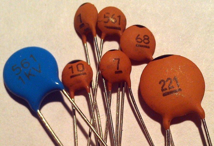
I am trying to read/test some cheap ceramic caps I got and am having trouble. I am hoping someone to add to my knowledge here.

I have looked at dozens of cap codes charts, read my DMM manual, and am stuck. Might just be limitation of my DMM?

The readings I get are not consistent with the charts or codes I have looked at. Also the DMM (you have to use "REL" mode for very low value caps) if it shows a value in nF, it will not show any value in uF which is -higher- so why would it not show the same value with decimal moved 2 places to the right? Right?  ???

Any insight or info much appreciated!
C

DMM I have is Radio Shack 22-812 w following spec for capaciatance- I do not fully understand what the limits of this DMM are even after looking at this spec:


Some of the caps-


Images showing some tests (note this DMM can be calibrated which I have not done but don't imagine it is needed)
(images removed)

Post showing calibration and other stuff:
http://www.candlepowerforums.com/vb/showthread.php?261833-Playing-with-the-RadioShack-22-812-Meter
#11
Hey guys!

What a night. Not only did my pres win the election (whew!), I breadboarded my first circuit!
I made plenty of mistakes but luckily removed power before the IC got too hot and fried. (True story.)

I just so happened to have cleaned out some stuff earlier today and found an old intercom kit someone left here years ago- and I had looked over the parts and noticed a couple of ICs which I identified as LM386 chips.
Fast forward a few hours and I am looking at culturejams website and see his "Dead Easy Dirt" circuit and realize I have the LM386 it needs, plus I bought some bags of random value caps and such from Radio Shack thinking I would prob never use them but the 2.2uF cap I needed was in there too. I also had parts from an old tuner I took apart etc. I did not have the suggested  diodes though.

I really wanted to use the scematic but sadly I just could not get past the IC pins- made no sense to me even when comparing with the perf board layout. I ended up using the perf and stripboard layouts and used the schem for reference occasionally.

First try-  I had the cap wired wrong and the IC heated up but it did actually pass signal. Fixed the cap and still passed signal but sounded awful and noisy as shit. The IC did not heat up though- progress.

Removed other things/adapters from power strip- that helped noise.

I looked up the diodes I had used (1N4004) and compared them with the ones I was supposed to use (1N914) and learned the difference between rectifying and switching diodes. I used rectifying which can handle more V but are relatively slow to switch unlike the ones specified which handle much less V but are very fast.
I just used some tiny glass ones that looked similar from the Boss TU-2 tuner I had mined for parts.
They worked MUCH better!

The thing was still squealing and noisy so I took readings at the suggestion of this page over at DIYSB:
http://www.diystompboxes.com/smfforum/index.php?topic=29816.0

Then I realized one of the diodes was not connected- my add-on legs were a bit wonky- I made sure they were connected and it sounded even better and the readings I had taken changed. (I tested continuity of everything at first though which was also helpful for learning how the breadboard works)

In any event, very exciting. I need to spend more time thinking about it to try and better understand how it actually works.

-too much voltage can be an issue (yay sag knob on my test rig!)
-grounding and power source can contribute a lot to noise
-the diode readings are VERY curious and interesting- that info is below the pic- I wont go into that but even though the diodes are flipped the K and A on each side have the same readings. Also seeing negative voltages in some spots was def not expected!

Silly long post but damn this was fun. I ended up trying to play "Let The Good Times Roll" by the Cars. hah

Regards,
C


Supply voltage: 8.92V BATTERY (does not seem to like the 9.76V of wall wart unless I sag it a bit)
(one pot position which produces squeal: pot 1-2 is 76K, 1-3 is 76K, 2-3 is 255R)

IC1: LM386N-1
1: 1.26V slow fall
2: 0.2mV
3: -0.1mV
4: 1mV
5: 4.41V
6: 8.83V
7: 4.5V
8: 1.26V slow fall

C1: 2.2uF electrolytic
+: 4.39V
-: 2.0mV

D1: unknown glass diode
A: 1.8mV (-369mV first, remove probe then goes positive)
K: banded 0.2mV

D2: unknown glass diode
A: 0.2mV
K: banded 1.8mV (-369mV first, remove probe then goes positive)

100K pot fully CW:
1: to ground: 0.1mV
2: to output: -370mV
3: from D1: -370mV

D2 was disconnected at one point and many values changed after slightly but most dramatic were pot values 2 and 3 which went from -127mV to -370mV
this also made a lot of the craziness and noise stop
removing other adapters from power strip stopped a lot of noise too
#12
Hi there,

In the process of learning about and building pedals I have run into an issue many times and that is:

There are a lot of things about components and circuits that people know but beginners do not AND this info is often times not easily explained or easy to find.

If you do find it it is rarely expressed like:

"resistors can always be installed in either direction"
"always test a resistor before installing- never blindly trust the label and color bands can often be hard to id"
"a pot with 3 legs will always have one of the outer legs to x and the center leg will always be to ground"
"you can reverse how a pot works by which outer leg you choose to use"
"if something needs to be grounded ANY ground point will work, not just the one specified in the build doc"
etc. (heh, these could be wrong too)

These are not really great examples but what I am trying to get at is all the knowledge and bits of info that people with experience know but beginners do not.

Most folks are not going to go to an electronics class or read books on the subject and even then it is like user manuals- some provide those wonderful insights throughout (Korg for example) while others provide only a basic description of functions and methods with NO insights or common sense info alongside.

GOAL:
To create a source of information for people to reference that contains this sort of basic but useful information.

Suggested Methods:
A public Google doc that people can add to themselves OR users can add info to a thread and I can maintain a doc that people can view/download. Maybe organized by items:
Circuts/PCB- "boards"
Resistors
Capacitors or "caps"
Potentiometers- "pots"- "variable resistor"
etc.

I know there are places for "A Beginners Guide to Pedal Building" like at GuitarPCB and such but I want to capture the fundamental things and condense them into one place. I want to try and gather and condense all those bits of info that experienced users have had to learn and research and discover for themselves and put it in one place.
This is not a substitute for learning on your own but it can be really frustrating to try and find out how to wire a pot but never find the fundamental concepts of a pot explained or useful insights and constants about how a part or thing works or behaves, only "you wire it like this, the end"

Hope this makes sense-
Does this sound like a good idea to anyone? What do you think? I'd love your thoughts and feedback.

C

EDIT:
heh, having to search on your own really does have its advantages however- just found an interesting if basic NASA page when looking to see what "axial" components were:
http://workmanship.nasa.gov/lib/insp/2%20books/links/sections/609%20Axial%20Components.html

http://workmanship.nasa.gov/lib/insp/2%20books/frameset.html
#13
Hi,

I LOVE my Zombii, but it is a bit frustrating to have to turn the guitar down and back up every time I use it. Also I love using it with my Macheen but same issue but even harder because the Macheen LIKES full output from guitar but then the Macheen overloads the Zombii.

Are there any mods that could change this? It is like the circuit does not like the "normal" output level of a guitar but more like half the output. or is it an impedance issue? Heck if I know. I just know as wild of a fuzz it is it is also the best transparent dirt pedal I have right now.

Thx,
C
#14
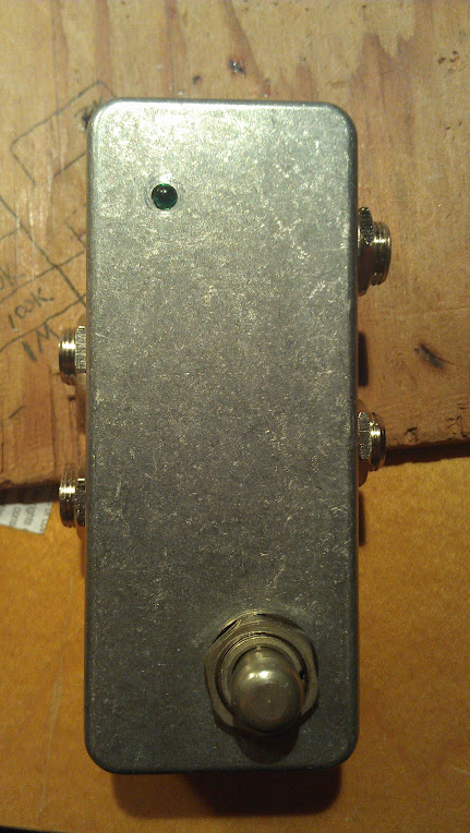
This was fun!

Clickless kit from AMZFX - http://www.muzique.com/schem/bypass.htm

I would like to do a graphic or treatment to the enclosure eventually. I used my new step bit- wow- so nice!! Didn't power up, then I tested continuity on the 9v jack and realized I hooked up to the wrong + tab- I always forget they are not the same. (I have a spare male/male power lead it comes in handy for testing)
Works great! There can be some mild popping depending on what you have turned on in the fx loop.  
I also used some parts from other things- a tiny green LED from a broken tuner and the SPDT I borrowed from an FS-300- so glad I thought of that as I didn't want to order just that one switch.
Need to spend more time carefully measuring for drilling holes but I get all excited and cut corners sometimes- had to use the dremel to make one of the jacks fit- :)


#15
This app is really cool- just wanted to let folks know of another source of helpful info for your obsession:
https://play.google.com/store/apps/details?id=it.android.demi.elettronica&hl=en
They also have a parts source plugin for the US but I have not tried that.
#16
Open Discussion / LEDs that respond to effects
October 11, 2012, 07:14:30 PM
I am looking to see if there is a general way to add LEDs to a project that respond to the audio. With a delay it would be cool to have it respond to the delays and not the input signal. Any links to threads appreciated.
C
#17
Just wondering if anyone has any suggestions as to an octave or delay project that has any particular suitability for a bass player. I am making a gift for a friend. I am almost tempted to build a double box with a Smoothie and Lowrider but the Lowrider looks pretty involved.
Thanks-
C
#18
Hi- meet my new Frankenstein test rig!

Hoping someone can suggest an error. I went for a more complex test rig than the basic one. I am 99% sure I do not have any solder bridges or bad joints. I am suspecting the pot wiring but not sure.

PROBLEM:
Not getting V through the black/red test leads (w alligator clips) while on DC jack but works (including sag which is an Alpha 1K pot) on battery (tested w DMM).
/PROBLEM

LED works on batt w 1/4" in input. LED works on DC jack power with or without 1/4" input. 2nd DC jack not wired but eventually I want it to be on sag like clips. Also I do not currently have a circuit to use the test rig on- what I did was used a spare battery clip to try and power a pedal with and to test the sag function.

I went off various info- Beavis, main test rig thread here, and this build thread by Josh (gtr2) w sag- http://www.madbeanpedals.com/forum/index.php?topic=784.0
But mainly I used the MB standard wiring diagram for main reference.

Connections as currently wired:
+9V on jack--> LED/resistors, +battery clip lead,  far left lug of pot (referenced pic in Josh's thread)
-9V on jack--> sleeve of input 1/4" jack (verified grounding through chassis for all ground points and with 3PDT switch in both positions)
Test leads:
input (green)--> center lug on 3PDT
output (yellow)--> upper right lug on 3PDT
+V (red)--> middle lug on pot
-V (black)--> middle row far left lug on 3PDT

Far right lug on pot--> resistor to ground (3 resistors equaling 2.2K)

On slim chance a photo might be of use in diagnosing...
#19
http://www.madbeanpedals.com/builds/index.html (3 links at bottom)

These are so funny and encouraging. Everyone starts somewhere and to see some of Brian's history and humor is really great.

C
#20
Open Discussion / Project Development Blog link
September 30, 2012, 10:19:28 AM
Been searching for info on what upcoming projects ARE and tired of searching the names and such- I found this and for some reason took me forever to find it again so here it is anyway-

http://www.madbeanpedals.com/forum/index.php?board=23.0