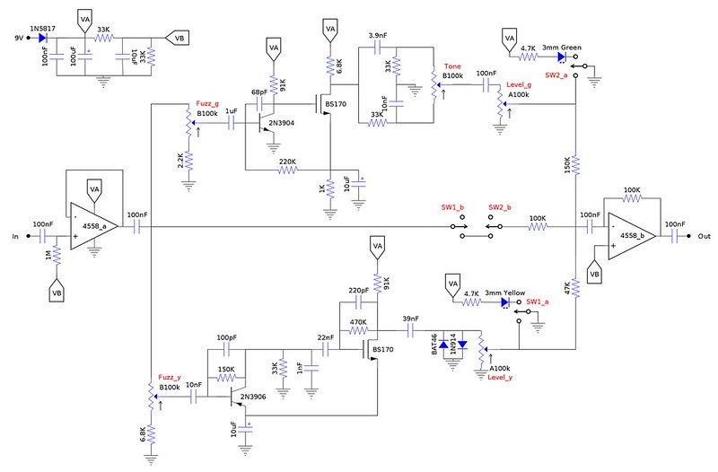
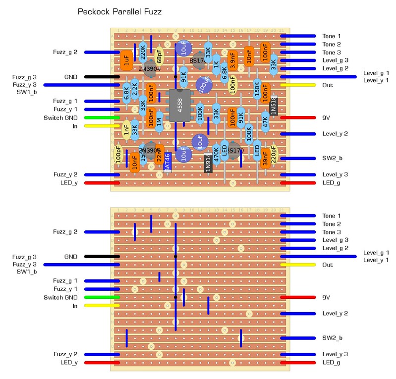
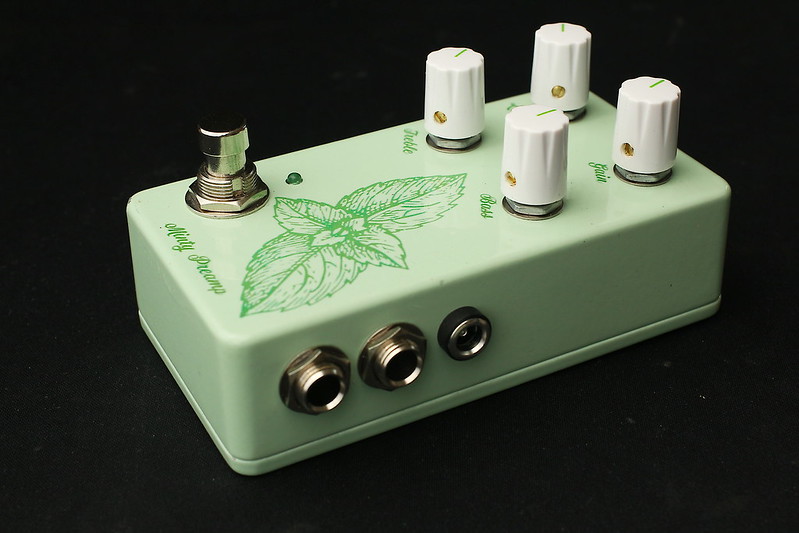
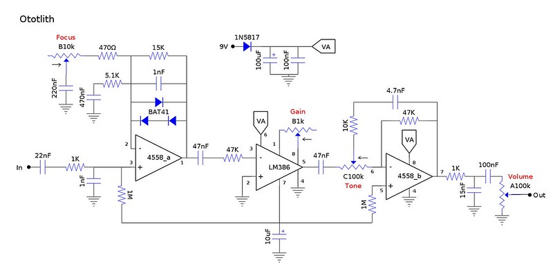
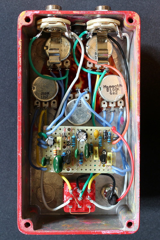
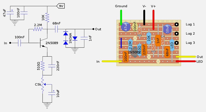
While I was very happy with the circuit, I was never happy with the finish on my original vero build. Having decided to learn to design PCBs, this circuit seemed like a good candidate. The thread on the original goes into details about the circuit, but basically it's a short delay with envelop control pitch bending. This makes for unique chorus, doubling, slap back, and vibrato effects.

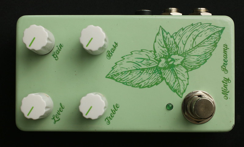
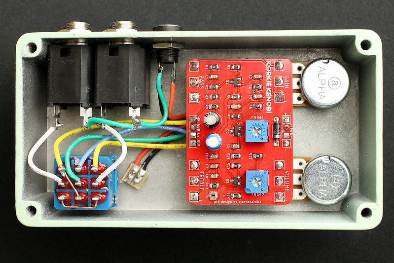
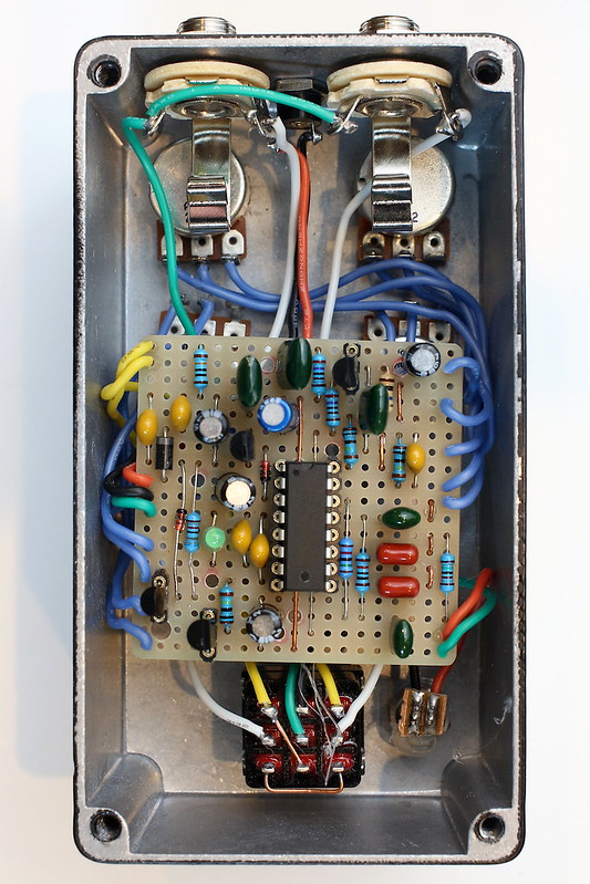
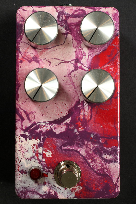
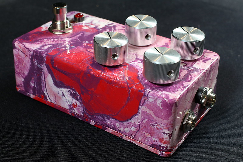
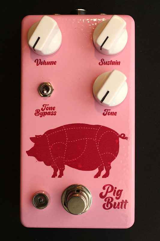
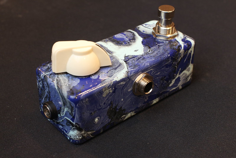
The enclosure is a Love My Switches limited run. The face plate is a one-sided aluminum PCB from JLCPCB.

The face plate made finishing a breeze and makes it easier to hide mis-drilled holes!

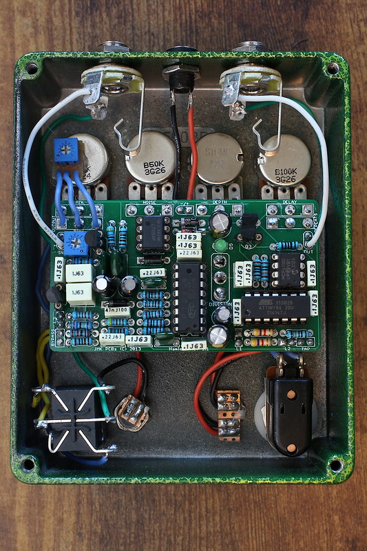
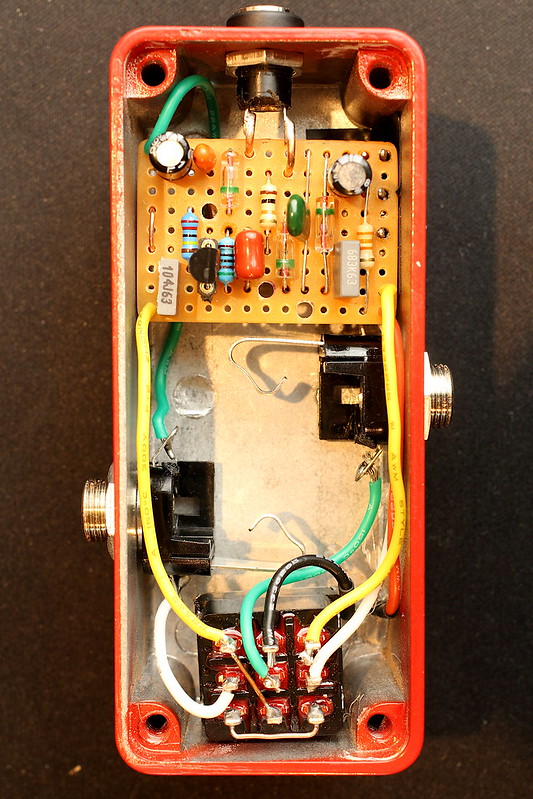
I've been experimenting with ribbon cable and am liking the results. I'm considering making daughter boards for bypass and inputs for future projects to streamline things further.

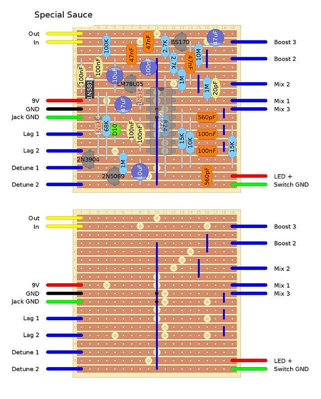
The circuit is unchanged except for the boost section. The boost has been revoiced to cut frequencies below 140Hz or so. At the lowest setting, there is no frequency cut. The boost gets "brighter" as the gain is increased. This keeps things tight when boosting into an overdrive or dirty amp.
Here's the original demo.
I have extra PCBs and face plates. If anyone is interested in building this, please DM me.
The enclosure is a Love My Switches limited run. The face plate is a one-sided aluminum PCB from JLCPCB.
The face plate made finishing a breeze and makes it easier to hide mis-drilled holes!
I've been experimenting with ribbon cable and am liking the results. I'm considering making daughter boards for bypass and inputs for future projects to streamline things further.
The circuit is unchanged except for the boost section. The boost has been revoiced to cut frequencies below 140Hz or so. At the lowest setting, there is no frequency cut. The boost gets "brighter" as the gain is increased. This keeps things tight when boosting into an overdrive or dirty amp.
Here's the original demo.
I have extra PCBs and face plates. If anyone is interested in building this, please DM me.